

Page 1
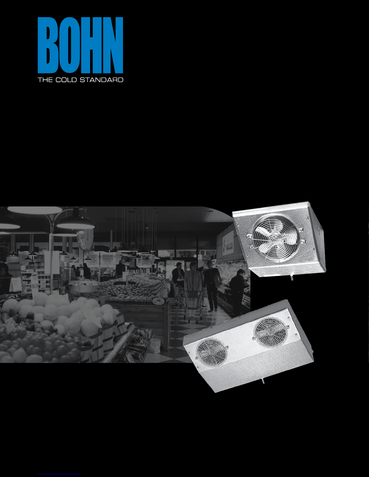
REACHIN UNIT COOLERS
Technical Guide
Models TA, TL, C, VA, BBM, BBL, KMK, RAMK, BTO & U
BNRITB
January 2004
(Replaces 107.2, 01/04)
Page 2

Table of Contents
Model TA Thin Prole Air Defrost ................................................................................................................... 3
Model TL Thin Prole Electric Defrost ..........................................................................................................
Model C High Prole ..........................................................................................................................................
Model VA Vee-Aire ..............................................................................................................................................
Models BBM/BBL Back Bar ...............................................................................................................................
Model KMK Kompact Mullion .........................................................................................................................
Model RAMK Reverse Air Flow Kompact Mullion ....................................................................................
Model BTO Twin Flow ......................................................................................................................................
Model U ................................................................................................................................................................
4
5
6
7
8
9
10
11
2
©2007 Heatcraft Refrigeration Products LLC
Page 3
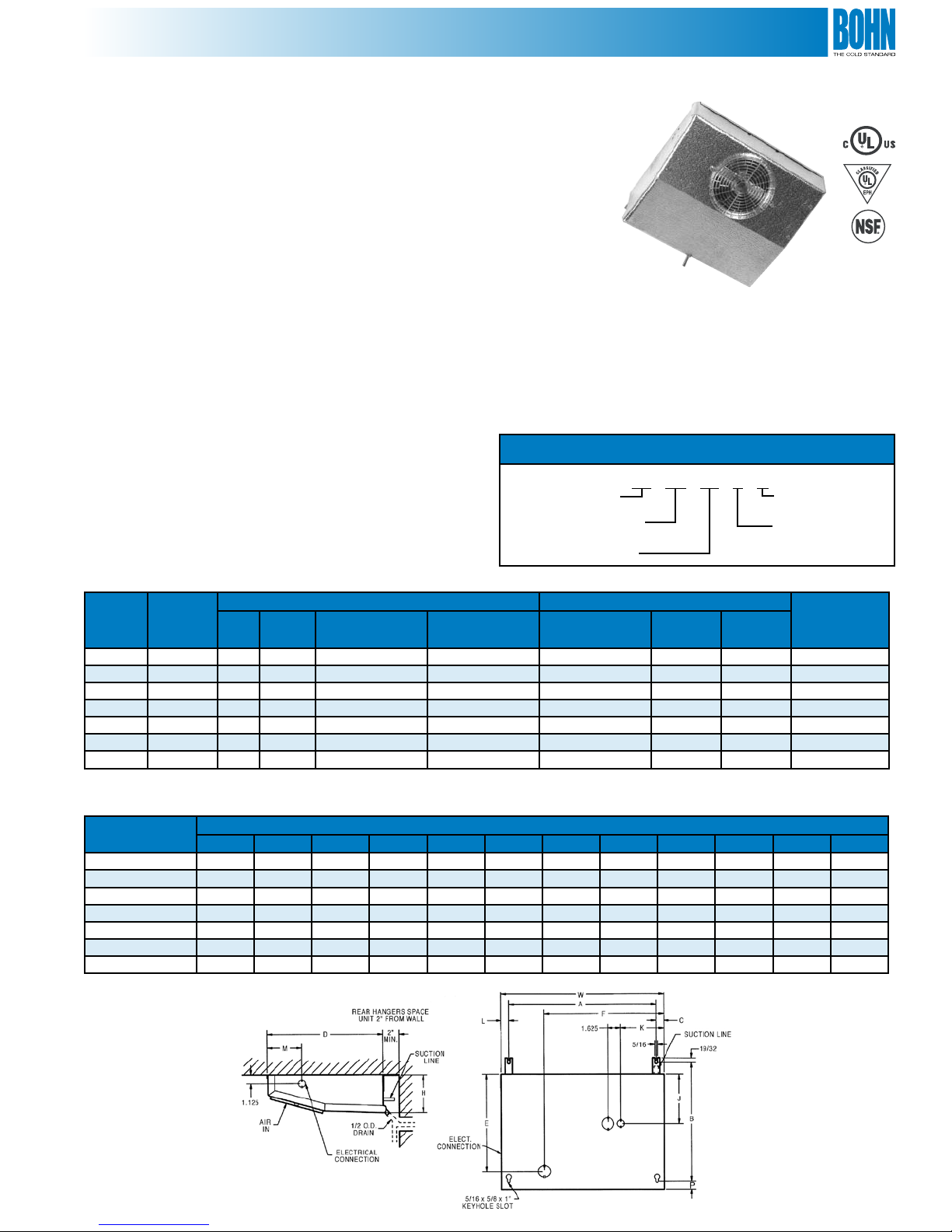
Model TA
Thin Prole Air Defrost Reach-In Unit Cooler
Features
• Textured aluminum cabinet
• Molded Lexan® guards and fans
• Drain tting mounted at 45-degree angle so drain
can be run through back or bottom of refrigerator
• Room for expansion valve inside the unit
• Stainless steel screws
• Motors are thermally protected and
permanently lubricated
• Convenient, moistureproof motor plug
• Compact design! Does a big job in a small space
• Optional Bohn-Kote® coated coil available (Model TAK)
for optimum protection in corrosive environments
• Internal junction box for electrical connection
• All models are UL listed for the US and Canada
• UL classied to NSF standards
Sweat inlet connection to reduce leaks
(are connection available as a ship loose option)
Application
Model TA is a thin prole unit which mounts in the top of
a refrigerator and makes the entire top shelf area usable. The
attractive low silhouette makes the unit particularly desirable
for display type refrigerators. It can also be used in back bars,
under counter cabinets, or wherever space is at a premium.
For 35° to 45°F xtures at 10° to 15° TD applications with 16
hours maximum compressor run time per day.
Nomenclature
Thin Prole Air Defrost
TA (K) 17 B G
Bohn-Kote® Coil
(Optional)
Size
Vintage
Voltage
A = 115/1/60
B = 208-230/1/60
Table 1. Performance and Electrical Data
Model
TA10 1,000 120 1 0.8 0.4 3/8 3/8 1/2 14
TA13 1,300 170 2 1.6 0.8 3/8 3/8 1/2 17
TA17 1,700 210 2 1.6 0.8 3/8 3/8 1/2 21
TA23 2,300 330 3 2.4 1.2 3/8 3/8 1/2 28
TA30 3,000 360 3 2.4 1.2 3/8 1/2 1/2 33
TA43
TA55
†
Models 43 and 55 use external equalized expansion valve
BTUH
10°F TD
†
4,300 540 4 3.2 1.6 1/2 5/8 1/2 44
†
5,500 650 5 4.0 2.0 1/2 5/8 1/2 53
CFM Qty.
Motor Data Connections (in.) Approx.
115/1/60
Total FLA
208-230/1/60
Total FLA
Coil Inlet
OD
SuctionIDDrain
OD
Table 2. Physical Data
Model
TA10 14-5/8 14 15/16 13-1/2 10-1/2 11-3/8 4-1/2 8-7/8 2-1/2 15/16 4-3/8 16-1/2
TA13 18-5/8 14 15/16 13-1/2 10-1/8 10-1/4 4-1/2 8-3/8 9-1/2 15/16 4-3/8 20-1/2
TA17 22-1/8 15 15/16 14-1/2 11-1/8 12 4-1/2 9-3/8 11-1/4 15/16 4-3/8 24
TA23 29-3/4 15 15/16 14-1/2 13 20-7/8 4-1/2 10-3/4 10-1/4 15/16 4-3/8 31-5/8
TA30 38-1/8 15 15/16 14-1/2 13 29-3/4 4-1/2 10-3/4 9-3/4 15/16 4-3/8 40
TA43 51-1/2 15 15/16 14-1/2 13 48-3/4 4-1/2 10-3/4 13-1/4 15/16 4-3/8 53-3/8
TA55 51-1/2 15 15/16 14-1/2 13 49 6-3/4 10-3/4 11 15/16 4-3/8 53-3/8
A B C D E F H J K L M W
Dimensions (in.)
Diagram 1. Dimensions
Ship Wt.
(lbs.)
3
Page 4
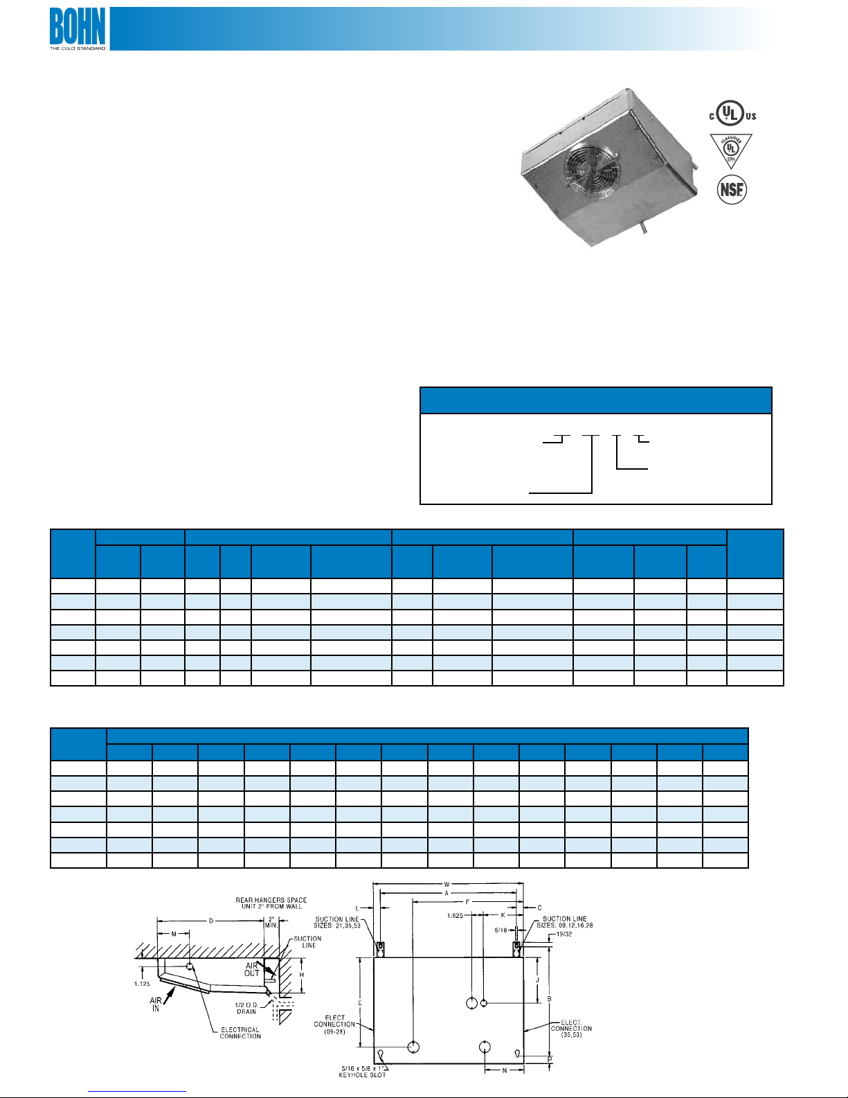
Model TL
Thin Prole Electric Defrost Reach-In Unit Cooler
Features
• Electric defrost insures positive heat source
• Built-in fan delay allows coil to be chilled before returning
to the normal cooling cycle
• Defrost terminates on coil temperature eliminating
excessive defrost period
• Textured aluminum cabinet
• Molded Lexan® guard
• Knockouts provided on sides for electrical
connections - opening in rear for coil connections
• Stainless steel screws
• Motors are thermally protected and
permanently lubricated
• Internal junction box for electrical connection
• Plate type aluminum ns with full collars on expanded
copper tubes
• Coils are dehydrated and sealed
• Easy to install and maintain
• All models UL listed for the US and Canada
• UL classied to NSF standards
Sweat inlet connection to reduce leaks
(are connection available as a ship loose option)
Application
Model TL low temperature unit cooler has a completely
automatic defrost system. Mounted in the top of a refrigerator, its
extremely compact cabinet makes it possible to utilize the entire
top shelf area for storage. Having a normal operating range of
15°F to -20°F, this unit is ideally suited for such applications as
commercial freezers, ice cream boxes and bakery freezers.
Nomenclature
Thin Prole
Electric Defrost
Size
TL 12 B G
Vintage
Voltage
A = 115/1/60
B = 208-230/1/60
Table 3. Performance and Electrical Data
BTUH 10˚F TD Motor Data Heater Data Connections (in.) Approx.
Model
TL09 1,050 900 110 1 0.8 0.4 475 4.1 2.1 3/8 3/8 1/2 14
TL12 1,380 1,200 210 2 1.6 0.8 600 5.2 2.6 3/8 1/2 1/2 19
TL16 1,780 1,600 210 2 1.6 0.8 700 6.1 3.0 3/8 1/2 1/2 23
TL21 2,400 2,100 240 1 1.0 0.5 1,100 9.6 4.8 3/8 1/2 1/2 24
TL28 3,200 2,800 335 3 - 1.2 1,430 - 5.7 3/8 1/2 1/2 27
TL35* 4,000 3,500 420 2 - 1.0 1,600 - 7.0 1/2 5/8 1/2 38
TL53* 6,100 5,300 595 3 - 1.5 1,950 - 8.5 1/2 7/8 1/2 53
* Models 35 and 53 use external equalized expansion valves
20˚F
SST
-10˚F
SST
CFM Qty.
115/1/60
Total FLA
208-230/1/60
Total FLA
Watts
115/1/60
Amps
208-230/1/60
Amps
Coil InletODSuctionIDDrain
OD
Ship Wt.
Table 4. Physical Data
Model
TL09 14-5/8 14 15/16 13-1/2 10-1/2 11-3/8 4-1/2 8-7/8 2-1/2 15/16 4-3/8 - 1 16-1/2
TL12 18-5/8 14 15/16 13-1/2 10-1/8 10-1/4 4-1/2 8-3/8 9-1/2 15/16 4-3/8 - 1 20-1/2
TL16 22-1/8 15 15/16 14-1/2 11-1/8 12 4-1/2 9-3/8 11-1/4 15/16 4-3/8 - 1 24
TL21 22-1/8 16-1/2 15/16 16-1/2 14-1/2 18-7/8 6-3/4 11-7/8 17-1/4 15/16 4-3/8 - 1-1/2 24
TL28 29-3/4 15 15/16 14-1/2 13 20-3/4 6-3/4 9-3/4 9-7/8 15/16 4-3/8 - 1 31-5/8
TL35 35-3/4 16-1/2 15/16 16-1/2 14-1/2 33-1/4 6-3/4 11-5/8 18-3/8 15/16 6 5-1/8 1-1/2 38-3/8
TL53 46-1/2 16-1/2 1-1/8 16-1/2 14-1/2 44 6-3/4 11-5/8 30-3/8 1-1/2 6 5-1/8 1-1/2 49-1/8
A B C D E F H J K L M N P W
Dimensions (in.)
Diagram 2. Dimensions
(lbs.)
4
Page 5

Model C
High Prole Reach-In Unit Cooler
Features
• Textured aluminum cabinet
• Molded Lexan® guard
• Drain tting at 45-degree angle so drain can be run
through bottom or back of refrigerator
• Aluminum hangers automatically space the unit to the
correct distance from the back wall
• Stainless steel screws - prevent rust streaks
• Room for expansion valve inside the unit
• Knockouts in sides and top plus openings in rear provide
maximum exibility for electrical connection
• Full collar aluminum ns on expanded copper tubes
• Internal junction box with pigtail leads for
electrical connection
• Motors are thermally protected and
permanently lubricated
• All models UL listed for US and Canada
• UL classied to NSF standards
• Optional Bohn-Kote® coated coil available (Model CK)
for optimum protection in corrosive environments
Sweat inlet connection to reduce leaks
(are connection available as a ship loose option)
Application
Model C is the ideal unit for refrigerated reach-ins. It mounts
to the top of the refrigerator and discharges cold air against the
back wall. With this air ow pattern, the air is not blasted on
the product but is diused along the back wall and then gently
drawn across the product as it returns to the unit. Thus uniform
temperatures are maintained throughout the refrigerator. In
addition, door sweating and refrigeration loss due to door
opening is greatly reduced because the air is not discharged
against the doors.
Nomenclature
High Prole Unit Cooler
C (K) 43 B G
Bohn-Kote® Coil
(Optional)
Size
Vintage
Voltage
A = 115/1/60
B = 208-230/1/60
Table 5. Performance and Electrical Data
Model
C13 1,300 235 1 1.0 0.5 3/8 3/8 1/2 16
C17 1,700 250 1 1.0 0.5 3/8 1/2 1/2 17
C23 2,300 265 1 1.0 0.5 3/8 1/2 1/2 22
C30 3,000 480 2 2.0 1.0 3/8 1/2 1/2 27
C43
†
Model 43 uses external equalized expansion valve
BTUH
10°F TD
†
4,300 520 2 2.0 1.0 1/2 1/2 1/2 40
CFM Qty.
Motor Data Connections (in.) Approx.
115/1/60
Total FLA
208-230/1/60
Total FLA
Coil Inlet
OD
SuctionIDDrain
OD
Table 6. Physical Data
Model
C13 12-5/8 12-3/8 11-7/16 1-3/8 14-1/4
C17 15-5/8 12-3/8 14-7/16 1-3/8 17-1/4
C23 21-1/8 12-3/8 21-1/16 7/8 22-3/4
C30 26-1/8 12-3/8 25-13/16 1 27-3/4
C43 36-5/16 - - - 38
A B C D W
Dimensions (in.)
Diagram 3. Dimensions
Ship Wt.
(lbs.)
5
Page 6

Model VA
Vee-Aire Reach-In Unit Cooler
Features
• Textured aluminum cabinet
• Molded Lexan® fan guard
• Improved drain pan overlaps coil surface to catch
all condensate
• Stainless steel screws - prevent rust streaks
• Plate-type aluminum ns with full collars on
expanded copper tubes
• Expansion valve mounts inside cabinet
• Internal junction box for electrical connection
• Pigtail leads in junction box
• Motors are thermally protected and
permanently lubricated
• Top quality throughout in a compact size
• All models UL listed for US and Canada
• UL classied to NSF standards
• Optional Bohn-Kote® coated coil available (Model VAK)
for optimum protection in corrosive environments
Sweat inlet connection to reduce leaks
(are connection available as a ship loose option)
Application
Model VA is a deluxe unit designed for use in small reach-
ins, back bar and under counter refrigerators, and many other
applications where a small, compact unit is required. The thermal
expansion valve mounts inside the unit. The unit can be mounted
from the ceiling or o the back wall or end walls.
Nomenclature
V Prole Unit Cooler
VA (K) 08 A G
Bohn-Kote® Coil
(Optional)
Size
Vintage
Voltage
A = 115/1/60
B = 208-230/1/60
Table 7. Performance and Electrical Data
Model
VA06 600 135 1 0.8 0.4 3/8 3/8 1/2 9
VA08 800 130 1 0.8 0.4 3/8 3/8 1/2 9
VA12 1,200 265 2 1.6 0.8 3/8 3/8 1/2 14
VA17 1,700 245 1 1.0 0.5 3/8 3/8 1/2 11
BTUH
10°F TD
CFM Qty.
Motor Data Connections (in.) Approx.
115/1/60
Total FLA
208-230/1/60
Total FLA
Coil Inlet
OD
SuctionIDDrain
OD
Table 8. Physical Data
Model
VA06 4-5/16 13-1/4 4-5/16 - - 3-3/8 6-7/8 5-1/4 8-1/8 12-1/2
VA08 4-5/16 13-1/4 4-5/16 - - 3-3/8 6-7/8 5-1/4 8-1/8 12-1/4
VA12 4-1/2 18-3/4 5-5/16 - - 3-3/8 8 4-7/8 8-1/8 18
VA17 5-1/4 14-3/4 5-1/4 9 2-1/2 4 9-3/4 6-13/16 10-1/2 14
A B C D E F H J K W
Dimensions (in.)
Diagram 4. Dimensions
Ship Wt.
(lbs.)
6
Page 7

Models BBM/BBL
Back Bar Reach-In Unit Cooler
Features
• Molded Lexan® fan guards
• Coils have copper tubes with aluminum ns, mechanicallybonded for ecient heat transfer. The coils are dehydrated
and sealed
• Textured aluminum cabinet
• Knockouts are conveniently located for refrigerant lines
• Screws are hardened, stainless steel with a bright
zinc plating
• Expansion valve mounts inside the cabinet and
connections are sweat-type
• Motors are thermally protected and
permanently lubricated
• Master units include the basic unit plus factory mounted
expansion valve, solenoid, and temperature control. Also
right-hand piping extended 8” - 12” outside the housing,
sealed and pressurized to 20 - 30 PSI. A 1/4” OD liquid feed
to slave is included
• Slave units include the basic unit plus factory mounted
expansion valve with left-hand piping extended 8” - 12”
outside the housing, sealed and pressurized to 20 - 30 PSI
Sweat inlet connection to reduce leaks
(are connection available as a ship loose option)
Table 9. Performance and Electrical Data
BTUH
Model
BBM11 1,100 90 1 1/150 0.8 0.4 - - -
BBM16 1,600 180 2 1/150 1.6 0.8 - - -
10°F
CFM Qty. HP
TD
BBL10 1,000 90 1 1/150 0.8 0.4 275 2.7 1.4
BBL15 1,500 180 2 1/150 1.6 0.8 350 3.5 1.7
Motor Data Defrost Heaters
115/1/60
Total FLA
208230/1/60
Total FLA
Watts
115/1/60
Application
Models BB are compact, wall-mounted units whose low
height makes them ideal for undercounter reach-in or drawertype xtures. The unit draws air in at the bottom and discharges
out the front. An optional air deector is included and can be
mounted over the center of the fan to direct air up and out. The
deector can be eld-formed to direct the air where needed,
usually onto drop-in trays of condiments in salad bar or sandwich
preparation xtures. An S-type mounting angle is included
to position the unit 3/4” o the wall which gives optimum air
circulation and performance.
The BBM (medium temperature) model is designed for 35°
to 40°F xture temperature with o-cycle defrost. The unit
is designed to operate at 10° to 17° TD and 16 hours per day
compressor run time.
The BBL (low temperature) model is designed for 0° to -10°F
xture temperature, and has automatic electric defrost. The
unit is designed to operate at 8° to 15° TD with 18 hours per
day compressor runtime. The BBL has an incoloy sheath heater
embedded in the bottom n surface for ecient and fast
defrosting. A drain pan heater is included to insure complete
condensate drainage. A disc-type sealed defrost termination/
fan delay control is mounted and wired. Field connectors are
located at the terminal board.
Amps
230/1/60
Amps
208-
Back Bar Unit Cooler
L = Low Temp. Unit
M = Med. Temp. Unit
Blank = Standard Unit
S = Slave Unit
M = Master Unit
Nomenclature
BB L S 10 A G
Vintage
Voltage
A = 115/1/60
B = 208-230/1/60
Size
Table 10. Physical Data
Model
BBL10 19-1/8 18 17-1/2 7-1/16 - 16-5/8 19-3/4 17
BBM11 19-1/8 18 17-1/2 7-1/16 - 16-5/8 19-3/4 16
BBL15 25-5/8 24-1/2 24 4-13/16 8-5/8 23-1/8 26-1/4 20
BBM16 25-5/8 24-1/2 24 4-13/16 8-5/8 23-1/8 26-1/4 19
NOTES: All units have 3/8” OD suction, 1/2” OD sweat inlet and 1/2” OD drain
A B C D E F W
Dimensions (in.) Approx.
Diagram 5. Dimensions
Ship Wt. (lbs.)
Typical Section of
Sandwich Station
Model BBM
7
Page 8

Model KMK
Kompact Mullion Reach-In Unit Cooler
Features
• Light grained aluminum cabinets
• PVC coated fan guard
• Stainless steel hardware
• Coils have full collar aluminum ns on expanded
copper tubes
• Bohn-Kote® coated coil for optimum protection in
corrosive environments
• Refrigerant connection knockouts provided on both
ends of unit
• Expansion valve mounts inside the unit
• Motors are thermally protected and
permanently lubricated
• Internal junction box for electrical connection
• Adjustable air deector included provides dierent air
patterns. Air can be directed where its needed
• All models UL listed for the US and Canada
• UL classied to NSF standards
Sweat inlet connection to reduce leaks
(are connection available as a ship loose option)
Application
Model KMK is ideal for under-counter reach-in refrigerators.
The thin line design allows the unit to be mounted behind the
mullion with sucient clearance for tray slides. A down ow fan
arrangement is used with air drawn in at the top and discharged
at the bottom. This design provides superior air circulation and
insures uniform temperature throughout the cabinet.
This versatile design is also adaptable for mounting on the back
wall or ends of a cooler. The method of air circulation insures
minimum box temperature rise when the cabinet doors are
open. Ideal for bottle goods and beverage coolers.
Exclusive Bohn-Kote® Finish is Standard
The nned coil is protected by Bohn-Kote® - a special dip
coating that is baked on. Bohn-Kote® prevents corrosion of the
coil caused by acids that are present in salad dressings, spiced
meats and other food products.
Table 11. Performance and Electrical Data
BTUH
Model
KMK13 1,300 180 2 1.6 0.8 3/8 3/8 5/8 19
KMK17 1,700 170 2 1.6 0.8 3/8 3/8 5/8 20
KMK23 2,300 255 3 2.4 1.2 3/8 1/2 5/8 28
10°F
TD
CFM Qty.
Table 12. Physical Data
Model
KMK13 17-3/4 16-7/8 9 15-5/8 2-3/4 5-1/2 6-15/16
KMK17 19-3/4 16-7/8 10 15-5/8 2-3/4 6-1/2 7-15/16
KMK23 19-3/4 23-1/4 10 22 2-5/16 6-1/2 7-15/16
H L M W X Y Z
Motor Data Connections (in.) Approx.
115/1/60
Total FLA
208-230/1/60
Total FLA
Coil InletODSuctionIDDrain
OD
Nomenclature
Dimensions (in.)
Kompact Mullion
Bohn-Kote® Coil
KM K 13 A G
Size
Diagram 6. Dimensions
Ship Wt.
(lbs.)
Vintage
Voltage
A = 115/1/60
B = 208-230/1/60
8
Page 9

Model RAMK
Reverse Air Flow Kompact Mullion Reach-In Unit Cooler
Features
• Textured aluminum cabinet
• PVC coated fan guard
• Stainless steel hardware
• Coils have full collar aluminum ns on expanded
copper tubes
• Bohn-Kote® coated coil for optimum protection in
corrosive environments
• Refrigerant connection knockouts provided on both
ends of unit
• Expansion valve mounts inside the unit
• Motors are thermally protected and
permanently lubricated
• Internal junction box for electrical connection
• Adjustable air deector included provides dierent
air patterns. Air can be directed where its needed
• All models are UL listed for the US and Canada
• UL classied to NSF standards
Sweat inlet connection to reduce leaks
(are connection available as a ship loose option)
Table 13. Performance and Electrical Data
BTUH
Model
RAMK13 1,300 180 2 1.6 0.8 3/8 3/8 5/8 19
RAMK17 1,700 170 2 1.6 0.8 3/8 3/8 5/8 20
RAMK23 2,300 255 3 2.4 1.2 3/8 1/2 5/8 28
10°F
TD
CFM Qty.
Motor Data Connections (in.) Approx.
115/1/60
Total FLA
208-230/1/60
Total FLA
Application
Model RAMK is ideal for under-counter reach-in refrigerators,
under-counter drawer type refrigerators and salad bars. The
unit is suitable for mounting behind a mullion or on a wall. An
up ow air pattern is used with air drawn in at the bottom and
discharged out the top. This provides optimum temperature for
drop in trays on salad bars or prep tables. It also keep drawer
stored product in premium condition.
An adjustable and detachable air deector/splash protector
is included. The deector can be adjusted to direct the air up
and out at a 45-degree angle. This feature provides excellent
air distribution over drop in trays or containers. Food in the
trays and containers stays colder, lasts longer, and retains the
desired appearance. The deector can be adjusted to distribute
air out both sides when used as a mullion unit.
Exclusive Bohn-Kote® Finish is Standard
The nned coil is protected by Bohn-Kote® - a special dip coating
that is baked on to prevent corrosion of the coil by acids that
are present in salad dressings, spiced meats and other food
products.
Coil InletODSuctionIDDrain
Ship Wt.
OD
(lbs.)
Table 14. Physical Data
Model
RAMK13 17-3/4 16-7/8 9 15-5/8 2-3/4 5-1/2 6-15/16
RAMK17 19-3/4 16-7/8 10 15-5/8 2-3/4 6-1/2 7-15/16
RAMK23 19-3/4 23-1/4 10 22 2-5/16 6-1/2 7-15/16
H L M W X Y Z
Dimensions (in.)
Diagram 7. Dimensions
Reverse Air Flow
Kompact Mullion
Bohn-Kote® Coil
Nomenclature
RAM K 13 A G
Size
Vintage
Voltage
A = 115/1/60
B = 208-230/1/60
9
Page 10

Model BTO
Twin Flow Reach-In Unit Cooler
Features
• Compact two-way design with medium velocity air ow
• Mounts ush to the ceiling and draws air in through the
fan and discharges out both sides
• Air pattern reduces air loss when doors are opened and the
medium velocity reduces product drying
• Textured aluminum cabinet
• Stainless steel fasteners
• Molded Lexan® fan guards
• Drain pan and fan panel is easily removed for
installation and servicing
• Optional Bohn-Kote® coated coil available (Model BTOK)
for optimum protection in corrosive environments
• Coils are constructed of copper tubing with aluminum ns
• Expansion valve mounts inside the cabinet
• Internal junction box is provided for electrical connection
• Motors are thermally protected and
permanently lubricated
• All models are UL listed for the US and Canada
• UL classied to NSF standards
Sweat inlet connection to reduce leaks
(are connection available as a ship loose option)
Table 15. Performance and Electrical Data
Model
BTO09 900 1,350 130 1 0.8 0.4 1/2 1/2 1/2 12
BTO13 1,300 1,950 240 2 1.6 0.8 1/2 1/2 1/2 14
BTO18 1,800 2,700 255 1 1.0 0.5 1/2 1/2 1/2 15
BTO25* 2,500 3,750 460 2 2.0 1.0 1/2 1/2 1/2 23
BTO35* 3,500 5,250 425 2 2.0 1.0 1/2 1/2 1/2 24
BTO45* 4,500 6,750 550 2 2.0 1.0 1/2 1/2 5/8 34
BTO55* 5,500 8,250 730 1 2.1 1.1 1/2 1/2 5/8 34
†
Models 25, 35, 45 and 55 use external equalized expansion valve
BTUH
10°F TD
BTUH
15°F TD
CFM Qty.
Motor Data Connections (in.) Approx.
115/1/60
Total FLA
Table 16. Physical Data
Model
BTO09 16-1/8 19-1/8 7-9/16 4 2-5/16 9-9/16 2-3/4 4-7/8 4-1/2 8-5/8 2-1/2 2-5/8 4-9/16 10 7/8
BTO13 16-1/8 19-1/8 7-9/16 4 2-5/16 9-9/16 2-3/4 5-3/4 4-1/2 8-5/8 2-1/2 2-5/8 4-9/16 10 7/8
BTO18 16-1/8 19-1/8 7-9/16 4 2-5/16 9-9/16 2-3/4 5-3/4 4-1/2 8-5/8 2-1/2 2-5/8 4-9/16 10 7/8
BTO25 18-1/8 26-1/8 11-1/16 4 2-5/16 13-1/16 2-3/4 6-3/4 5-1/2 12-1/8 3-1/2 2-5/8 8-1/16 10 7/8
BTO35 18-1/8 26-1/8 11-1/16 4 2-5/16 13-1/16 2-3/4 6-3/4 5-1/2 12-1/8 3-1/2 2-5/8 8-1/16 10 7/8
BTO45 21-1/8 29-1/8 8-3/16 7-3/4 3-7/16 10-5/8 3-1/2 9-1/4 8 13-5/8 5-15/16 4-1/4 7-9/16 14 1-3/4
BTO55 21-1/8 29-1/8 8-3/16 7-3/4 3-7/16 10-5/8 3-1/2 8-1/2 8 13-5/8 5-15/16 4-1/4 7-9/16 14 1-3/4
A B C D E F G H J K L M N P R
Application
Model BTO is ideal for temperatures of 35°F and higher. Box
temperatures are kept more constant throughout and fresh
products last longer. Seven sizes are available with BTUH from
900 to 5,500 at 10° TD.
Larger BTO sizes are suitable for large reach-in and small step-in
or walk-in coolers.
Nomenclature
Twin Flow Unit Cooler
208-230/1/60
Total FLA
Dimensions (in.)
BTO K 09 A G
Bohn-Kote® Coil
(Optional)
Size
Coil InletODSuctionIDDrain
Vintage
Voltage
A = 115/1/60
B = 208-230/1/60
OD
Ship Wt.
(lbs.)
Diagram 8. Dimensions
10
Page 11

Model U
Reach-In Unit Cooler
Features
• Textured aluminum cabinet
• Full collar aluminum ns on expanded copper tubes
• Detachable drain pan that is easy to clean
• Molded 3-prong motor connector to save installation
time and expense
• Motors are thermally protected and
permanently lubricated
• Optional Bohn-Kote® coated coil available (Model UK)
for optimum protection in corrosive environments
• All models are UL listed for the US and Canada
• UL classied to NSF standards
Sweat inlet connection to reduce leaks
(are connection available as a ship loose option)
Application
Model U is used wherever a small, compact unit is required.
It can be mounted on the ceiling or wall. The model U unit
draws air through the front and discharges it out both sides
to insure proper distribution of cool air and thus maintain a
uniform box temperature.
Nomenclature
Dual Aire Standard Coil
Bohn-Kote® Coil
(Optional)
U K 09 0
Size
Voltage
0 = 115/1/60
1 = 208-230/1/60
Table 17. Performance and Electrical Data
Model
U09 850 1,275 190 0.45 0.55 1/2 3/8 1/2 9
U12 1,150 1,725 250 0.45 0.55 1/2 3/8 1/2 10
U15 1,500 2,250 310 1.10 0.55 1/2 3/8 1/2 14
BTUH
10°F TD
BTUH
15°F TD
CFM
Motor Data Connections (in.) Approx.
115/1/60
Total FLA
208-230/1/60
Total FLA
Coil InletFNSuctionIDDrain
OD
Table 18. Physical Data
Model
U09 8-1/2 11-1/2 8-7/8 6 4 3-1/2
U12 8-1/2 17-1/2 8-7/8 12 4 9-1/2
U15 9-1/2 17-1/2 10-7/8 12 4 9-1/2
H W D A B C
Dimensions (in.)
Diagram 9. Dimensions
Ship Wt.
(lbs.)
11
Page 12

For more information on Bohn refrigeration products, contact
your Sales Representative or visit us at www.thecoldstandard.com.
A Brand of Heatcraft Refrigeration Products LLC
2175 West Park Place Blvd. • Stone Mountain, GA • 30087
(800) 537-7775 • FAX (770) 465-5990
www.thecoldstandard.com
Since product improvement is a continuing eort, we reserve the right to
make changes in specications without notice.
BN-RITB 1107 | version 000
 Loading...