

Page 1
Replaces BN-HSWCUTB, December 2009
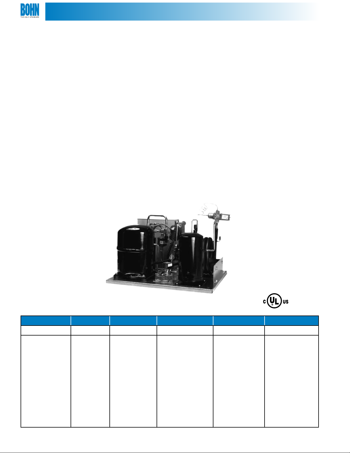
WATERCOOLED CONDENSING UNITS
Technical Guide
Models HWN | Hermetic • ZWN | Scroll
BNHSWCUTB
March 2011
Page 2
®
TABLE OF CONTENTS
Nomenclature....................................................................................................... ................................................2
Features & Benets. ............................................................................................ ................................................3
Application Data .................................................................................................. ................................................4
Unit Specications .............................................................................................................................................. 5
Performance Data ........................................................................................................................................... 6-8
Physical and Dimensional Data ..................................................................................................................... 9
Electrical Data ............................................................................................................................................. 10-11
NOMENCLATURE
N.Y. MEA
ZW N 030 L 6 B
Compressor Application Equiv. HP Temp. Refrigerant Voltage
HW = Hermetic
ZW = Scroll
N = Indoor 005 = 1/2HP
008 = 3/4HP
010 = 1HP
01* = 1-1/2HP
H = High
L = Low
M = Medium
X = Medium/Low
2 = R-22
6 = R-404A/507
B = 208/230/1/60
C = 208/230/3/60
D = 460/3/60
02* = 2HP
03* = 3HP
04* = 4HP
05* = 5HP
060 = 6HP
2
Page 3
®
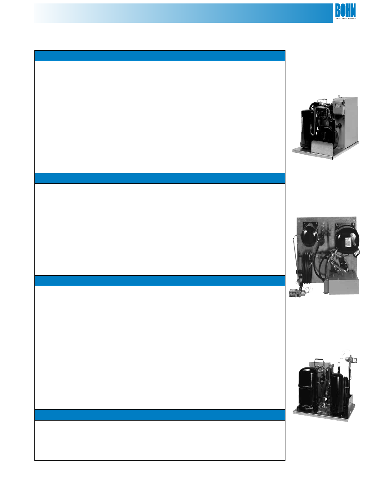
FEATURES & BENEFITS
Construction
• Component location and unit size are all optimized for easy eld
replacements or new installations where space is limited.
• Extra space is provided inside the electrical box for service and installation
of additional components.
• Copeland hermetic and scroll compressors for low and medium temperature
operation using R-22 and R404A.
• All units are provided with a water regulating valve for superior head
pressure control.
• An extra capacity receiver with liquid shut-o valve is provided for
installations with long refrigerant lines.
• A pumpdown switch is provided on all models for eld servicing.
Serviceability
• Easy access to the large electrical panel for service diagnostics or options.
• Color-coded wire harnesses are all labeled and coded for easy identication.
• A suction line rotolock service valve is provided on the compressor
for service.
• An additional shut o valve is mounted in the discharge line of the
compressor for quick and easy compressor to enable the service technician to
isolate the compressor for service.
• Schrader valves permit recovery of refrigerant isolated in compressor for
quick and easy compressor change if ever needed.
Quality
• Piping is laid out to minimize stress and vibration for quieter operation.
• Easy to verify leak-free unit by checking for the nitrogen holding charge
Schrader valve on the discharge or suction service valve.
• Encapsulated, automatic reset, high pressure control, and an adjustable low
pressure control with exible refrigerant hose to reduce possibility for leaks.
• A helix tube in tube water cooled condenser is standard with refrigerant
counter ow for optimum condensing unit eciency.
• Every unit is put into a vacuum and subjected to a rigorous leak test. This
results in a clean, dry and leak free unit every time.
• Electrical circuits are factory tested for functional integrity.
• Every unit is run tested and cycled on both the high and low pressure
controls.
Option
• Sight glass (optional) is easily viewable from the front to monitor the
refrigerant charge.
• Factory-installed suction lter available as option for additional system
protection.
3
Page 4
®
APPLICATION DATA
Installation Precautions
All units are factory charged with dry nitrogen which must be evacuated prior to installation.
Water valves must be adjusted during initial start-up to design condensing pressure for the selected refrigerant.
All HW “X6” models require a suction accumulator. HW “X6” models with RS compressors are not suitable for R-507.
Retrot Installations
If a P.O.E. model is used in a retrot, the old mineral oil must be completely removed from the system or at least
reduced to no more than 5% of the total oil charge. Polyolester oil is very hygroscopic. Take extra precautions to
limit exposure to the atmosphere.
Leveling Units
Unit must be level to insure proper oil return to the compressor.
Condenser Water Temperature
Maximum leaving water temperature is 105°F on all models.
Condenser Water Treatment
The use of untreated or improperly treated water may result in scaling
premature erosion or corrosion. A qualied water treatment specialist is
recommended for proper results.
Engineering Aids
Total Heat of Rejection (THR) all units:
THR = BTUH + (KW x 1000 x 3.4 x 1.0)
Water Temperature Rise (∆T
water cooled condenser:
∆T
= THR ÷ (GPM x 60 x 8.4)
w
) through
w
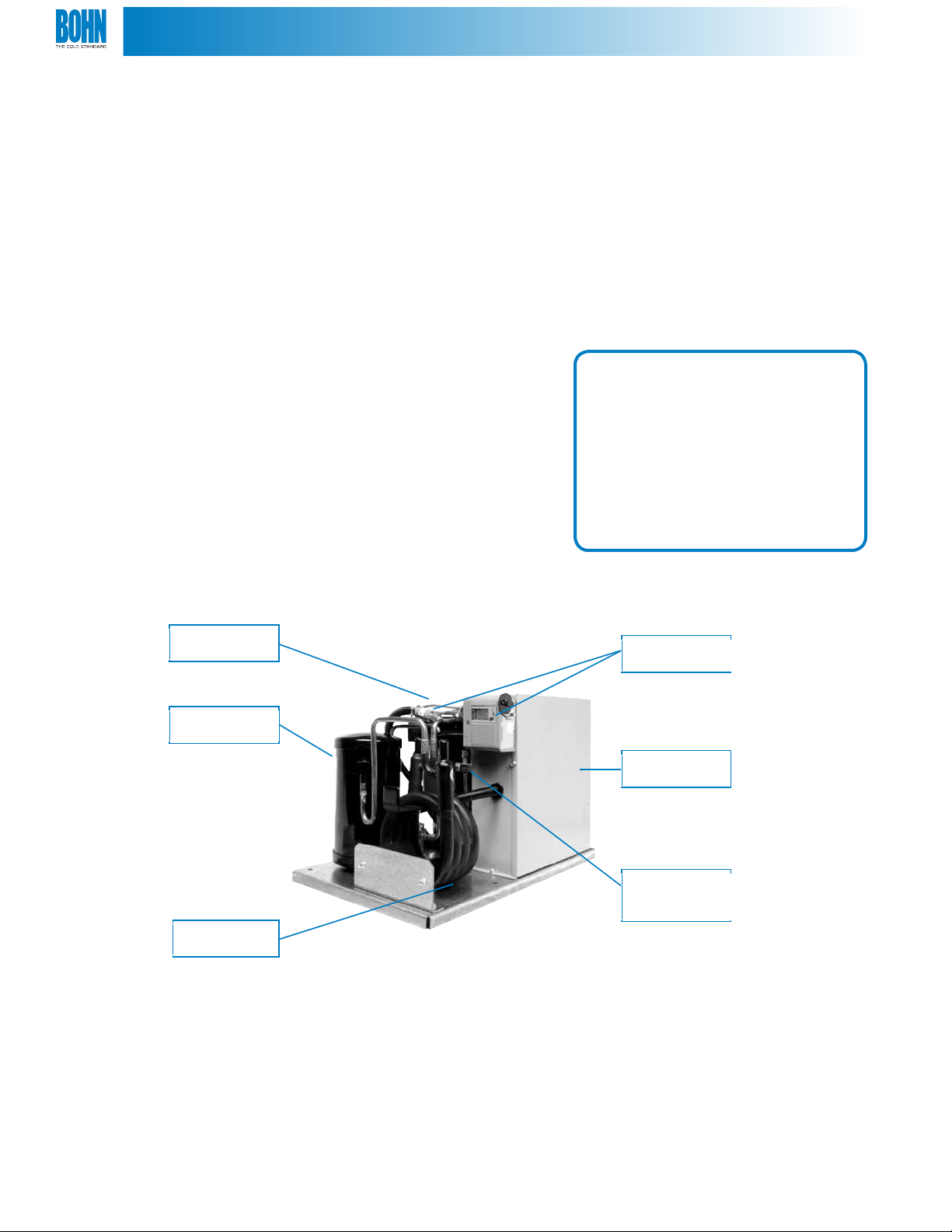
Hermetic
Compressor
Large
Receiver
Coaxial
Condenser
High & Low
Pressure Controls
Spacious
Control Box
Refrigerant
Isolation Service
Valves (2)
4
Page 5

®
UNIT SPECIFICATIONS
Features & Specications HW ZW
Compressor mounting (rubber grommets) Standard Standard
Compressor discharge service valve (in line brass base valve) Standard Standard
Compressor suction service valve - rotolock Standard Standard
Large capacity refrigerant receiver (up to 100 ft. runs) Standard Standard
Receiver service valve (located on outlet) Standard Standard
Coaxial condenser (counterow tube in tube) Standard Standard
Extra large electric box (encloses all options and capacitors) Standard Standard
Electric conduit (UL recognized, high impact, ame retardant copolymer) Standard Standard
Low pressure control switch (adjustable) Standard Standard
High pressure encapsulated safety switch (xed) Standard Standard
Super hose on low pressure control (higher leak resistance) Standard Standard
Voltage 208-230 - 1ph - 60hz Standard Standard
Voltage 208-230 -3ph - 60hz Standard Standard
Voltage 460 - 3ph - 60hz Standard Standard
Pump down control switch (pre-wired) Standard Standard
Water valve (mounted on condenser inlet) Standard Standard
Agency approvals UL, ULC, N.Y., MEA 106-98-E Standard Standard
Electrical Options HW ZW
Air defrost timer Option Option
Electric defrost timer Option Option
Electric defrost timer with contractor Option Option
Compressor crankcase heater¹ Option Option
Beacon II™ Control Option Option
Mechanical Options HW ZW
Liquid line drier & sight glass assembly (sweat)² Option Option
Liquid line solenoid valve (230V coil) Option Option
Suction lter with bypass Option Option
Suction accumulator Option Option
Suction accumulator & lter Option Option
Two-tiered stacking rack for eld assembly Option Option
¹ Crankcase heaters are not required for indoor operation but are included in all HW models. Field wiring is required. ZW models crankscase heaters are not available.
² Required on ZW “L6” models
The Beacon II system is a pre-assembled, factory installed refrigeration system
featuring an intregrated microcomputer-based electronic control board. System
orders (including matching unit coolers) are now available for all HW & ZW models.
The Beacon II system replaces the expansion valve, solenoid valve, room thermostat,
defrost control timer. It comes factory preset thereby eliminating all of the expensive and time consuming
ne tuning and adjustments necessary for a good system installation. For additional information, see the Beacon II
bulletin or contact your local Sales Representative.
5
Page 6

®
PERFORMANCE DATA
Hermetic Compressors - High & Medium Temperature Models
Model
HWN005H2 ART82C1
HWN008H2 RS64C2
HN010H2 RS70C1
HWN015H2 CR18KQ
HWN020H2 CR24KQ
HWN030H2 CR37KQ
HWN040H2 CR53KQ
HWN050H2 CRN5-0500
Capacity ratings conditions: 85°F entering water, 105°F condensing, 20°F ITD, 0°F subcooling. (ITD = Condensing temperature - entering condenser water temperature)
BTUH = British Thermal Units (All capacities are rated at 60 Hz operation)
GPM = Gallons per Minute (Water ow rate)
PSI = Pounds per Square Inch (Water pressure drop through condenser)
Compressor
R-22
0°F 10°F 20°F 30°F 40°F
BTUH 3,220 4,220 5,390 6,860 8,760
GPM 0.7 1.0 1.3 1.8 3.0
PSI 0.4 0.6 1.0 1.6 2.7
BTUH 3,840 5,530 7,500 9,820 11,990
GPM 0.6 1.1 1.5 2.1 2.7
PSI 0.4 0.6 1.0 1.6 2.7
BTUH 4,550 6,600 8,810 11,350 14,280
GPM 0.5 1.3 1.8 2.7 3.8
PSI 0.4 1.2 2.1 4.1 6.8
BTUH 5,700 8,190 11,240 14,860 19,100
GPM 1.5 1.8 2.6 3.7 6.1
PSI 0.5 0.6 1.1 2.0 4.0
BTUH 7,120 10,330 14,330 19,190 25,100
GPM 1.1 1.8 3.2 4.9 8.0
PSI 0.5 0.8 1.7 3.3 8.0
BTUH 11,950 17,140 23,660 31,640 41,470
GPM 1.4 2.0 4.2 6.8 13.0
PSI 0.6 0.9 1.8 3.7 9.9
BTUH 14,850 23,880 33,740 44,620 56,820
GPM 5.1 5.8 7.5 12 18.0
PSI 1.9 2.2 3.0 6.7 12.7
BTUH 21,510 30,630 40,460 51,570 64,890
GPM 4.0 6.1 9.0 13.5 12.0
PSI 0.9 1.5 3.0 6.1 13.1
Suction Temperature °F
Hermetic Compressors - High Temperature Models
Model
HWN005H6 RST45C1E
HWN009H6 RST64C1E
HWN010H6 RS70C1E
HWN015H6 CS10K6E
HWN025H6 CS14K6E
HWN032H6 CS20K6E
HWN040H6 CS27K6E
HWN050H6 CS33K6E
Compressor
BTU/H 7,370 8,160
GPM 1.3 1.5
PSI 1.0 1.2
BTU/H 11,190 12,310
GPM 1.8 2.1
PSI 2.1 2.6
BTU/H 12,430 13,900
GPM 2.0 2.3
PSI 2.3 2.9
BTU/H 18,510 20,830
GPM 3.3 3.9
PSI 1.6 2.2
BTU/H 25,060 27,910
GPM 4.8 5.7
PSI 3.2 4.2
BTU/H 36,490 40,790
GPM 5.6 6.8
PSI 2.7 3.7
BTU/H 48,220 53,600
GPM 10.3 12.8
PSI 7.5 11.3
BTU/H 53,250 59,150
GPM 8.7 10.3
PSI 2.8 3.8
Suction Temperature °F
35°F 40°F
Capacity ratings conditions: 85°F entering water, 110°F condensing, 25°F ITD, 0°F subcooling
6
Page 7

®
PERFORMANCE DATA
Hermetic Compressors - Extended Temperature Models
Model
HWN005X6 RST45C1E
HWN008X6 RST55C1E
HWN009X6 RST64C1E
HWN010X6 RS70C1E
HWN015X6 CS10K6E
HWN020X6 CS12K6E
HWN025X6 CS14K6E
HWN030X6 CS18K6E
HWN032X6 CS20K6E
HWN040X6 CS27K6E
HWN050X6 CS33K6E
Compressor
R-404A
Suction Temperature
°F
25°F 20°F 10°F 0°F 10°F 20°F 30°F
BTUH 1,280 1,665 2,460 3,290 4,220 5,270 6,480
GPM 0.2 0.2 0.4 0.7 0.9 1.2 1.6
PSI 0.2 0.2 0.2 0.3 0.5 0.9 1.4
BTUH 2,060 2,340 3,070 4,010 5,140 6,460 7,950
GPM 0.4 0.5 0.7 1.0 1.4 1.9 2.6
PSI 0.2 0.3 0.4 0.6 1.1 1.7 3.0
BTUH 2,480 2,880 3,820 4,970 6,320 7,870 9,620
GPM 0.2 0.2 0.5 0.9 1.4 1.8 2.4
PSI 0.2 0.2 0.3 0.7 1.3 2.1 3.2
BTUH 1,600 2,335 3,770 5,200 6,800 8,700 11,200
GPM 0.3 0.3 0.4 1.1 1.5 1.8 2.7
PSI 0.3 0.3 0.3 0.9 1.5 2.1 3.9
BTUH 2,000 2,815 4,580 6,930 9,710 12,900 16,300
GPM 0.6 0.8 1.0 1.5 2.3 3.3 4.8
PSI 0.2 0.3 0.4 0.5 0.9 1.6 3.1
BTUH 2,650 3,615 5,670 8,340 11,490 15,100 19,200
GPM 0.8 0.9 1.6 1.8 2.8 4.3 6.6
PSI 0.4 0.4 0.5 0.6 1.2 2.6 4.3
BTUH 3,840 4,900 7,160 10,140 13,630 17,500 21,800
GPM 0.2 0.5 1.1 1.8 3.2 4.7 7.2
PSI 0.1 0.2 0.5 0.8 1.7 4.2 6.6
BTUH 4,590 5,825 8,570 12,600 17,400 22,700 28,300
GPM 0.5 0.9 1.5 2.9 4.9 8.0 10.5
PSI 0.2 0.4 0.6 1.4 3.3 8.0 10.4
BTUH 4,650 6,505 10,110 14,210 19,220 25,600 34,000
GPM 0.5 0.8 1.3 1.8 2.6 5.0 9.5
PSI 0.2 0.4 0.6 0.8 1.1 2.2 6.6
BTUH 6,819 8,628 12,406 17,547 23,901 31,622 40,740
GPM 0.8 1.3 1.8 2.7 5.5 10.8 15
PSI 0.4 0.6 0.8 1.2 2.6 8.1 13.6
BTUH 8,100 10,515 15,433 21,505 28,838 37,733 48,684
GPM 1.3 2.1 3.1 4.5 6.2 9.0 13.6
PSI 0.1 0.1 0.7 1.0 1.6 3.0 6.2
Hermetic Compressors - Low Temperature Models
Model
HWN011L6 CF04K6E
HWN014L6 CF06K6E
HWN025L6 CF09K6E
HWN031L6 CF12K6E
Capacity ratings conditions: 85°F entering water, 105°F condensing, 20°F ITD, 0°F subcooling. (ITD = Condensing temperature - entering condenser water temperature)
BTUH = British Thermal Units (All capacities are rated at 60 Hz operation)
GPM = Gallons per Minute (Water ow rate)
PSI = Pounds per Square Inch (Water pressure drop through condenser)
Compressor
R-404A
-30 °F 25°F 20°F 10°F 0°F 10°F
BTUH 2,080 2,810 3,570 5,310 7,590 10,680
GPM 0.5 0.7 1.0 1.6 3.0 6.0
PSI 0.2 0.4 0.6 1.4 3.7 7.4
BTUH 3,770 4,810 5,990 8,700 11,780 15,070
GPM 1.0 1.3 1.5 2.5 4.0 5.0
PSI 0.8 1.2 1.5 3.4 7.4 8.0
BTUH 5,560 7,040 8,720 12,590 17,060 21,970
GPM 1.0 1.5 2.0 3.5 5.8 8.5
PSI 0.2 0.6 0.8 2.0 4.4 8.5
BTUH 7,550 9,510 11,570 16,060 21,180 27,140
GPM 1.25 2.5 3.4 5.75 9.5 11.0
PSI 0.6 1.2 1.9 4.4 9.8 12.0
Suction Temperature °F
7
Page 8

®
PERFORMANCE DATA
Scroll Compressors - Extended Temperature Models
Model
ZWN030X6 ZS21K4E
ZWN035X6 ZS26K4E
ZWN045X6 ZS30K4E
ZWN055X6 ZS38K4E
ZWN060X6 ZS45K4E
Compressor
R-404A
-25 °F 20°F 10°F 0°F 10°F 20°F 30°F 40°F
BTUH 9,010 10,230 12,840 16,070 19,740 24,110 29,310 35,200
GPM 1.2 1.3 1.6 2 2.7 4.4 6.8 10.8
PSI 0.6 0.6 0.7 0.9 1.2 1.8 3.7 8.1
BTUH 11,270 12,740 15,910 19,930 24,490 29,950 36,400 43,650
GPM 4.6 5.1 5.2 5.6 6 6.8 8.8 12
PSI 1.9 1.9 1.9 2.1 2.3 2.6 3.9 6.7
BTUH 12,810 14,390 17,960 22,870 28,480 35,030 42,320 50,100
GPM 5.1 5.2 5.5 5.8 6.8 8.5 11.9 15.1
PSI 1.9 1.9 2 2.1 2.6 3.7 6.6 9.8
BTUH 15,920 18,050 22,640 28,420 34,970 42,780 51,980 62,350
GPM 3.1 3.4 4.8 5.8 7.5 10.3 14.5 21
PSI 0.5 0.6 1 1.1 2.2 3.8 7 13.1
BTUH 19,220 21,820 27,360 34,160 41,850 51,090 62,130 74,750
GPM 3.1 3.3 5 6.9 9 12.6 17.7 23.9
PSI 0.8 0.8 1.2 1.2 2 3.7 6.8 10.1
Scroll Compressors - Low Temperature Models
Model
ZWN030L6 ZF09K4E
ZWN035L6 ZF11K4E
ZWN045L6 ZF13K4E
ZWN055L6 ZF15K4E
ZWN060L6 ZF18K4E
Compressor
R-404A
-40°F 30°F 25°F 20°F 10°F 0°F
BTUH 6,380 8,270 9,300 10,500 13,200 16,300
GPM 1.8 2.3 2.6 3.0 4.3 6.5
PSI 0.6 0.9 1.1 1.3 2.6 4.1
BTUH 7,900 10,170 11,500 12,900 16,200 20,200
GPM 1.9 2.7 3.2 4.7 5.2 7.5
PSI 0.8 1.3 1.7 3.1 3.6 7.1
BTUH 8,570 11,480 13,200 15,000 19,100 23,800
GPM 2.6 3.6 4.5 5.2 8.0 10.1
PSI 1.2 2.1 2.9 3.6 8.0 10
BTUH 11,080 14,480 16,400 18,500 23,300 28,900
GPM 2.9 4.3 5.5 6.3 9.0 11.3
PSI 1.5 2.6 3.8 4.7 8.6 12.3
BTUH 13,260 17,260 19,500 22,000 27,700 34,500
GPM 2.5 4.2 4.5 5.5 9.0 13.1
PSI 1.1 1.8 2.1 2.6 6.0 11.1
Suction Temperature °F
Suction Temperature °F
Capacity ratings conditions: 85°F entering water, 105°F condensing, 20°F ITD, 0°F subcooling. (ITD = Condensing temperature - entering condenser water temperature)
BTUH = British Thermal Units (All capacities are rated at 60 Hz operation)
GPM = Gallons per Minute (Water ow rate)
PSI = Pounds per Square Inch (Water pressure drop through condenser)
8
Page 9

®
PHYSICAL AND DIMENSIONAL DATA
Connections (in.)
Model
HWN005H2 ART82C1 1/2 3/8 1/2 1/2 6 22 14 17 77
HWN005X6 RST45C1E 1/2 3/8 1/2 1/2 5.5 22 14 17 98
HWN008H2 RS64C2 1/2 3/8 1/2 1/2 6 22 14 17 92
HWN008X6 RST55C1E 1/2 3/8 1/2 1/2 5.5 22 14 17 98
HWN009X6 RST64C1E 5/8 3/8 1/2 1/2 5.5 22 14 17 103
HWN010H2 RS70C1 5/8 3/8 1/2 1/2 6 22 14 17 91
HWN010X6 RS70C1E 5/8 3/8 1/2 1/2 5.5 22 14 17 107
HWN011L6 CF04K6E 5/8 3/8 1/2 1/2 9 27 22 21 114
HWN014L6 CF06K6E 5/8 3/8 1/2 1/2 9 27 22 21 114
HWN015H2 CR18KQ 5/8 3/8 1/2 1/2 10 27 22 21 136
HWN015X6 CS10K6E 5/8 3/8 1/2 1/2 9 27 22 21 148
HWN020H2 CR24KQ 5/8 3/8 1/2 1/2 10 27 22 21 141
HWN020X6 CS12K6E 7/8 3/8 1/2 1/2 9 27 22 21 148
HWN025L6 CF09K6E 5/8 3/8 1/2 1/2 9 27 22 21 120
HWN025X6 CS14K6E 7/8 3/8 1/2 1/2 9 27 22 21 152
HWN030H2 CR37KQ 7/8 1/2 1/2 1/2 22 29 25 28 174
HWN030X6 CS18K6E 7/8 1/2 1/2 1/2 20 27 22 28 172
HWN031L6 CF12K6E 7/8 1/2 1/2 1/2 20 27 22 21 136
HWN032X6 CS20K6E 7/8 1/2 1/2 1/2 20 27 22 28 182
HWN040H2 CR53KQ 7/8 1/2 1/2 1/2 22 29 25 28 196
HWN040X6 CS27K6E 7/8 1/2 1/2 1/2 20 29 25 28 183
HWN050H2 CRN5-0500 7/8 1/2 3/4 3/4 22 29 25 28 221
HWN050X6 CS33K6E 7/8 1/2 1/2 1/2 20 29 25 28 207
ZWN030L6 ZF09K4E 7/8 1/2 1/2 1/2 20 27 22 28 159
ZWN030X6 ZS21K4E 7/8 1/2 1/2 1/2 20 29 25 28 171
ZWN035L6 ZF11K4E 7/8 1/2 1/2 1/2 20 27 22 28 165
ZWN035X6 ZS26K4E 7/8 1/2 1/2 1/2 20 29 25 28 186
ZWN045L6 ZF13K4E 7/8 1/2 1/2 1/2 20 27 22 28 185
ZWN045X6 ZS30K4E 7/8 1/2 1/2 1/2 20 29 25 28 207
ZWN055L6 ZF15K4E 7/8 1/2 1/2 1/2 20 27 22 28 201
ZWN055X6 ZS38K4E 7/8 1/2 3/4 3/4 20 29 25 28 226
ZWN060L6 ZF18K4E 7/8 1/2 1/2 1/2 20 29 25 28 207
ZWN060X6 ZS45K4E 7/8 1/2 3/4 3/4 20 29 25 28 241
HWN005H6 RST45C1E 1/2 3/8 1/2 1/2 5.5 22 14 17 98
HWN009H6 RST64C1E 5/8 3/8 1/2 1/2 5.5 22 14 17 103
HWN010H6 RS70C1E 5/8 3/8 1/2 1/2 5.5 22 14 17 107
HWN015H6 CS10K6E 5/8 3/8 1/2 1/2 9.0 27 22 21 148
HWN025H6 CS14K6E 7/8 3/8 1/2 1/2 9.0 27 22 21 152
HWN032H6 CS20K6E 7/8 1/2 1/2 1/2 20.0 27 22 28 182
HWN040H6 CS27K6E 7/8 1/2 1/2 1/2 20.0 29 25 28 183
HWN050H6 CS33K6E 7/8 1/2 1/2 1/2 20.0 29 25 28 207
Compressor
Suction Liquid Water In Water Out
(ODS) (ODS) (FPT) (MPT) D W H
Receiver
90% Full
Lbs.
Dimensions (in.)
Net Wt.
(lbs.)
ODS = Outside Diameter Sweat
FPT = Female Pipe Thread
MPT = Male Pipe Thread
H
W
D
9
Page 10

®
ELECTRICAL DATA
Hermetic Compressors
Model
Number
HWN005H2B ART82C1-CAV 208-230 1 60 5.9 30.0 15 15 20.0 20 15 8.0
HWN005X6B RST45C1E-CAV 208-230 1 60 4.6 26.5 15 15 20.0 20 15 8.0
HWN008H2B RS64C2-PAV 208-230 1 60 6.9 37.0 15 15 20.0 20 15 8.0
HWN008X6B RST55C1E-CAV 208-230 1 60 6.1 33.7 15 15 20.0 20 15 8.0
HWN009X6B RST64C1E-CAV 208-230 1 60 8.0 43.0 15 15 20.0 20 15 6.0
HWN010H2B RS70C1-PFV 208-230 1 60 6.3 34.2 15 15 20.0 20 15 7.0
HWN010H2C RS70C1-TFC 208-230 3 60 4.2 31.0 15 15 20.0 20 15 8.6
HWN010X6B RS0C1E-PFV 208-230 1 60 6.3 34.2 15 15 20.0 20 15 7.0
HWN010X6C RS70C1E-TFC 208-230 3 60 4.2 31.0 15 15 20.0 20 15 8.6
HWN011L6B CF04K6E-PFV 208-230 1 60 9.6 59.2 15 15 20.0 20 15 8.0
HWN011L6C CF04K6E-TF5 208-230 3 60 6.4 52.0 15 15 20.0 20 15 8.0
HWN014L6B CF06K6E-PFV 208-230 1 60 11.4 59.2 15 20 20.0 25 23 4.0
HWN014L6C CF06K6E-TF5 208-230 3 60 7.0 52.0 15 15 20.0 20 19 9.0
HWN015H2B CR18KQ-PFV 208-230 1 60 8.1 47.0 15 15 24.0 25 19 6.0
HWN015H2C CR18KQ-TF5 208-230 3 60 4.9 40.0 15 15 24.0 25 19 7.0
HWN015H2D CR18KQ-TFD 460 3 60 2.8 23.0 15 15 20.0 20 15 9.0
HWN015X6B CS10K6E-PFV 208-230 1 60 9.8 56.0 15 20 24.0 25 19 6.0
HWN015X6C CS10K6E-TF5 208-230 3 60 6.7 51.0 15 15 20.0 20 15 7.0
HWN020H2B CR24KQ-PFV 208-230 1 60 12.2 70.5 20 25 29.0 30 23 6.0
HWN020H2C CR24KQ-TF5 208-230 3 60 6.7 40.0 15 15 24.0 25 19 9.0
HWN020H2D CR24KQ-TFD 460 3 60 3.6 28.0 15 15 20.0 20 15 8.5
HWN020X6B CS12K6E-PFV 208-230 1 60 9.8 56.0 15 20 24.0 25 19 6.0
HWN020X6C CS12K6E-TF5 208-230 3 60 6.7 51.0 15 15 25.0 25 19 9.0
HWN025L6B CF09K6E-PFV 208-230 1 60 16.7 87.0 20 30 25.0 35 30 6.0
HWN025L6C CF09K6E-TF5 208-230 3 60 10.2 72.2 15 20 20.0 25 19 7.0
HWN025X6B CS14K6E-PFV 208-230 1 60 11.2 61.0 15 20 29.0 30 23 6.0
HWN025X6C CS14K6E-TF5 208-230 3 60 8.2 55.0 15 15 24.0 25 19 9.0
HWN025X6D CS14K6E-TFD 460 3 60 4.2 28.0 15 15 20.0 20 15 8.3
HWN030H2B CR37KQ-PFV 208-230 1 60 16.7 100.3 21 35
HWN030H2C CR37KQ-TF5 208-230 3 60 9.9 85.0 15 20 38.0 40 30 12.0
HWN030H2D CR37KQ-TFD 460 3 60 5.0 39.0 15 15 24.0 25 19 9.0
HWN030X6B CS18K6E-PFV 208-230 1 60 14.4 82.0 18 30 38.0 40 30 12.0
HWN030X6C CS18K6E-TF5 208-230 3 60 9.4 65.5 15 20 29.0 30 23 7.0
HWN030X6D CS18K6E-TFD 460 3 60 3.9 33.0 15 15 24.0 25 10 19.0
HWN031L6B CF12K6E-PFV 208-230 1 60 19.0 105.0 21 35 38.0 50 30 12.0
HWN031L6C CR12K6E-TF5 208-230 3 60 11.9 85.0 15 20 29.0 30 23 7.0
HWN031L6D CF12K6E-TFD 460 3 60 5.9 42.0 15 15 24.0 25 19 10.0
HWN032X6B CS20K6E-PFV 208-230 1 60 16.7 96.0 21 30 38.0 50 30 12.0
HWN032X6C CS20K6E-TF5 208-230 3 60 10.3 75.0 15 20 29.0 30 23 7.0
HWN032X6D CS20K6E-TFD 460 3 60 4.6 40.0 15 15 24.0 25 19 10.0
HWN040H2B CR53KQ-PFV 208-230 1 60 26.0 140.0 33 50 45.0 60 35 12.0
HWN040H2C CR53KQ-TF5 208-230 3 60 16.3 107.0 20 35 38.0 45 30 12.0
HWN040H2D CR35KQ-TFD 460 3 60 8.1 55.0 15 15 29.0 30 23 11.0
HWN040X6B CS27K6E-PFV 208-230 1 60 21.5 121.0 27 45 44.0 60 35 12.0
HWN040X6C CS27K6E-TF5 208-230 3 60 13.7 105.0 20 30 38.0 40 30 12.0
HWN040X6D CS27K6E-TFD 460 3 60 7.6 52.0 15 15 29.0 30 23 11.0
HWN050H2B CRN5-0500-PFV 208-230 1 60 30.8 142.0 39 50 59.0 60 47 12.0
HWN050H2C CRN5-0500-TF5 208-230 3 60 19.2 130.0 24 40 37.5 50 30 12.0
HWN050H2D CRN5-0500-TFD 460 3 60 8.7 65.0 15 15 29.0 30 23 10.0
HWN050X6B CS33K6E-PFV 208-230 1 60 27.6 1250 35 50 59.0 60 47 12.0
HWN050X6C CS33K6E-TFC 208-230 3 60 16.8 102.0 21 35 38.0 45 30 12.0
HWN050X6D CS33K6E-TFD 460 3 60 8.8 48.0 15 15 29.0 30 23 10.0
HWN005H6B RST45C1E-CAV 208-230 1 60 4.5 26.5 15 15 - - - HWN009H6B RST64C1E-CAV 208-230 1 60 7.6 43 15 15 - - - HWN010H6B RS70C1E-PFV 208-230 1 60 6.9 34.2 15 15 - - - HWN010H6C RS70C1E-TFC 208-230 3 60 4.7 31 15 15 - - - HWN015H6B CS10K6E-PFV 208-230 1 60 11.1 56 15 25 - - - HWN015H6C CS10K6E-TF5 208-230 3 60 7.2 51 15 15 - - - HWN025H6B CS14K6E-PFV 208-230 1 60 12.4 61 20 25 - - - HWN025H6C CS14K6E-TF5 208-230 3 60 8.5 55 15 15 - - - HWN032H6B CS20K6E-PFV 208-230 1 60 17.9 96 22.4 40 - - - HWN032H6C CS20K6E-TFS 208-230 3 60 13.3 75 20 30 - - - HWN040H6K CS27K6E-TF5 230 3 60 14.1 105 20 30 - - - HWN050H6K CS33K6E-TF5 230 3 60 16.5 102 20.7 35 - - - -
Compressor
Number
Power Supply Compressor
Volts Ph Hz+RLA LRA MCA MOPD MCA MOPD Amps Amps
Beacon II™ or
Air Defrost
Electric Defrost
38.0 45 30 12.0
Def.
Htr
Evap.
Fan
+
Consult Factory for 50 hz applications
RLA values have been calculated by dividing the maximum continuous current (MCC) by 1.56, per UL and National Electrical Code Standard.
RLA = Rated Load Amps LRA = Locked Rotor Amps
10
MCA = Minimum Circuit Ampacity MOPD = Maximum Overload Protection Device
Page 11

®
ELECTRICAL DATA
Scroll Compressors
Model
Number
ZWN030L6B ZF09K4E-PFV 208-230 1 60 14.7 88.0 18.0 30 38 45 30 12.0
ZWN030L6C ZF09K4E-TF5 208-230 3 60 9.9 77.0 15.0 20 24 25 19 6.0
ZWN030L6D ZF09K4E-TFD 460 3 60 5.1 39.0 15.0 15 24 25 19 10.0
ZWN030X6B ZS21K4E-PFV 208-230 1 60 14.7 88.0 18.4 30 38 45 30 12.0
ZWN030X6C ZS21K4E-TF5 208-230 3 60 9.9 77.0 15.0 20 38 40 30 12.0
ZWN030X6D ZS21K4E-TFD 460 3 60 5.1 39.0 15.0 15 24 25 19 10.0
ZWN035L6B ZF11K4E-PFV 208-230 1 60 18.6 109.0 23.0 40 38 50 30 12.0
ZWN035L6C ZF11K4E-TF5 208-230 3 60 12.2 88.0 15.0 25 29 30 23 6.0
ZWN035L6D ZF11K4E-TFD 460 3 60 6.4 44.0 15.0 15 24 25 19 10.0
ZWN035X6B ZS26K4E-PFV 208-230 1 60 18.6 109.0 23.2 40 38 50 30 12.0
ZWN035X6C ZS26K4E-TF5 208-230 3 60 12.2 88.0 15.2 25 38 40 30 12.0
ZWN035X6D ZS6K4E-TFD 460 3 60 6.4 44.0 15.0 15 24 25 19 9.0
ZWN045L6B ZF13K4E-PFV 208-230 1 60 24.0 129.0 30.0 50 41 60 30 11.0
ZWN045L6C ZF13K4E-TF5 208-230 3 60 13.5 99.0 17.0 30 38 40 30 11.0
ZWN045L6D ZF13K4E-TFD 460 3 60 7.4 49.5 15.0 15 24 25 19 9.0
ZWN045X6B ZS30K4E-PFV 208-230 1 60 24.0 129.0 30.0 50 59 60 47 11.0
ZWN045X6C ZS30K4E-TF5 208-230 3 60 13.5 99.0 17.0 30 44 45 35 12.0
ZWN045X6D ZS30K4E-TFD 460 3 60 7.4 49.5 15.0 15 29 30 23 11.0
ZWN055L6B ZF15K4E-PFV 208-230 1 60 28.8 169.0 36.0 60 38 60 30 10.0
ZWN055L6C ZF15K4E-TF5 208-230 3 60 19.2 123.0 24.0 40 38 50 30 10.0
ZWN055L6D ZF15K4E-TFD 460 3 60 8.7 62.0 15.0 15 25 25 19 8.0
ZWN055X6B ZS38K4E-PFV 208-230 1 60 28.8 169.0 36.0 60 59 60 47 12.0
ZWN055X6C ZS38K4E-TF5 208-230 3 60 19.2 123.0 24.0 40 44 50 35 12.0
ZWN055X6D ZS38K4E-TFD 460 3 60 8.7 62.0 15.0 15 29 30 23 10.0
ZWN060L6C ZF18K4E-TF5 208-230 3 60 21.5 156.0 27.0 45 44 60 35 12.0
ZWN060L6D ZF18K4E-TFD 460 3 60 8.3 70.0 15.0 15 29 30 23 11.0
ZWN060X6C ZS45K4E-TF5 208-230 3 60 21.5 156.0 27.0 45 38 60 30 12.0
ZWN060X6D ZS45K4E-TFD 460 3 60 8.3 70.0 15.0 15 29 30 23 10.6
+
Consult Factory for 50 hz applications
RLA values have been calculated by dividing the maximum continuous current (MCC) by 1.56, per UL and National Electrical Code Standard.
Compressor
Number
Power Supply Compressor
Volts Ph Hz+RLA LRA MCA MOPD MCA MOPD Amps Amps
Beacon II™ or
Air Defrost
Electric Defrost
Def.
Htr.
Evap.
Fan
RLA = Rated Load Amps
LRA = Locked Rotor Amps
MCA = Minimum Circuit Ampacity
MOPD = Maximum Overload Protection Device
11
Page 12

For more information on Bohn refrigeration products, contact
your sales representative or visit us at www.heatcraftrpd.com.
A Brand of Heatcraft Refrigeration Products LLC
2175 West Park Place Blvd. • Stone Mountain, GA • 30087
800.537.7775
www.heatcraftrpd.com
Since product improvement is a continuing eort, we reserve the right to
make changes in specications without notice.
 Loading...