

Page 1
Bulletin No� H-IM-AH August 2002 Part Number 4346B001
(Replaces H-IM-71A, August 2002)
Installation &
Operations Manual
Air Handler Unit
Table of Contents
Inspection �������������������������������������������������������������������������������������������������������������������������������������������������������������������������������������������������������������������������������������������������2
Shipment of Units
Handling
Suspended Units
Installation
Motors & Drives
Steam Coils
Steam Coils �����������������������������������������������������������������������������������������������������������������������������������������������������������������������������������������������������������������������������������������������3
Water Coils
Direct Expansion Coils
Start-up ������������������������������������������������������������������������������������������������������������������������������������������������������������������������������������������������������������������������������������������������������4
Maintenance
Condensate Drain Traps
Internal Isolation
Section Assembly �����������������������������������������������������������������������������������������������������������������������������������������������������������������������������������������������������������������������������������5
Coil Stacking
Freezing Temperatures �������������������������������������������������������������������������������������������������������������������������������������������������������������������������������������������������������������������������6
Weights ������������������������������������������������������������������������������������������������������������������������������������������������������������������������������������������������������������������������������������������������������7
Shipment of Sections
Filter Quantities ���������������������������������������������������������������������������������������������������������������������������������������������������������������������������������������������������������������������������������������8
Replacement Parts
Page 2

Installation and Operations Manual
Inspection
Shipment should be checked against the bill of lading
to verify that all items listed have been received� All
parts should be carefully inspected to determine if any
damage was incurred in shipment�
Any shortage and/or claims for damage should be
immediately reported to the delivering carrier, followed
by ling a claim for shortages and/or damages�
Shipment of Units
Depending on the unit size and accessories included, the
shipment may be in two or more sections�
Handling
Special care should be taken when handling and
assembling component sections of the unit� Rough
handling at the jobsite can result in damaged bearings,
bent shafts, etc�
All units are shipped on wooden skids� It is recommended
that units not be moved removed from skids until they
are at a place of installation� The mounting legs/rails
provided for isolators should be used when lifting units
into place�
Suspended Units
Sizes 03 through 41 may be ceiling-suspended from
the mounting legs/based rails with 5/8” diameter rods
(not furnished)� These rods will pass through the 11/16”
diameter mounting holes provided� Sizes 50, 65 and 75
cannot be ceiling-suspended�
Installation
It is very important that the unit be installed in a level
position to prevent distortion and to ensure proper
damper operation and coil drainage�
Allow sucient space around the unit for proper
maintenance� Consider factors such as lter removal for
cleaning or replacement, access to all removal panels,
removal of coils and shaft if necessary, lubrication access
or motor belt adjustment� Canvas duct connections
should be used between the unit and supply and return
air ducts�
Units are furnished with 1-1/4” FPT drain connection
on each side of the coil section� The drain line from
the drain pan connection must be adequately pitched
and should have a water seal of sucient depth to
compensate for the air pressure within the units�
(See Condensate Drain Traps on page 4�)
When the unit is located on the roof, it must be mounted
on support beams that span load-bearing walls� If not,
excessive vibration may occur because of the resiliency
of the roof�
2 Part # 4346B001
© 2007, Heatcraft Refrigeration Products LLC
Fan noise is a function of fan design, volume ow,
pressure and fan eciency and could be loud enough
to disturb those in occupied areas� Therefore, on critical
applications we recommend extra sound attention�
Motors and Drives
All units will normally be shipped with motor and drive
installed� When mounting a motor on the adjustable
base (installed on the unit), extreme care should be
taken to ensure proper alignment and belt tension� All
electrical work should be done in strict accordance with
local codes and regulations�
Steam Coils
Type J and NFS coils have supply and return connections
on the same end� Types R, S and RA coils have
supply and return connections on opposite ends�
Type NFD coils have supply connections on each end
of the coil, with a single return connection on one
end only�
All piping should be in accordance with accepted
industry standards and local codes� Support all piping
independent of coil and provide adequate swing joints in
all piping to absorb expansion and contraction strains�
Run return piping the full size of the coil return
connection from the coil to a dirt pocket� (Do not use
reducing ttings�) Install drip traps in steam mains ahead
of coils� Do not drip steam mains through the coils�
Install a vacuum breaker (1/2” 15º check valve) ahead
of the trap on low-pressure, open-gravity return systems
and on high pressure systems� Install a 1/2” 15º swing
check valve in a 1/2” vacuum-equalizing line, bypassing
the condensate trap, on low pressure vacuum systems�
When two or more steam coils are furnished in a unit,
provide separate traps for each coil� Size traps with ample
capacity using the maximum heating load and service
factor recommended by the trap manufacturer�
Select control valves in accordance with the
recommendations of the control manufacturer using
actual heating loads�
Install suitable strainer ahead of all automatic valves and
traps to catch dirt and scale� Provide adequate air vents
to expel air and other non-condensable material�
Control valves used for type J, NFS, RA and NFD coils
must be gradual-acting, modulating type with veeport�
Where a control valve is used for type S or R coils and
the entering air temperature is below 35ºF, use a twoposition valve� Locate control element in the entering air
Page 3
Air Handler Units
stream so that valve will remain open with a minimum
of ve pounds steam pressure when the entering air
temperature is below 35ºF� At system start-up, the
damper should remain closed for approximately ten
minutes after the steam valve is opened�
Properly locate all temperature sensing elements at a
point of true average air mixture temperature� Refer to
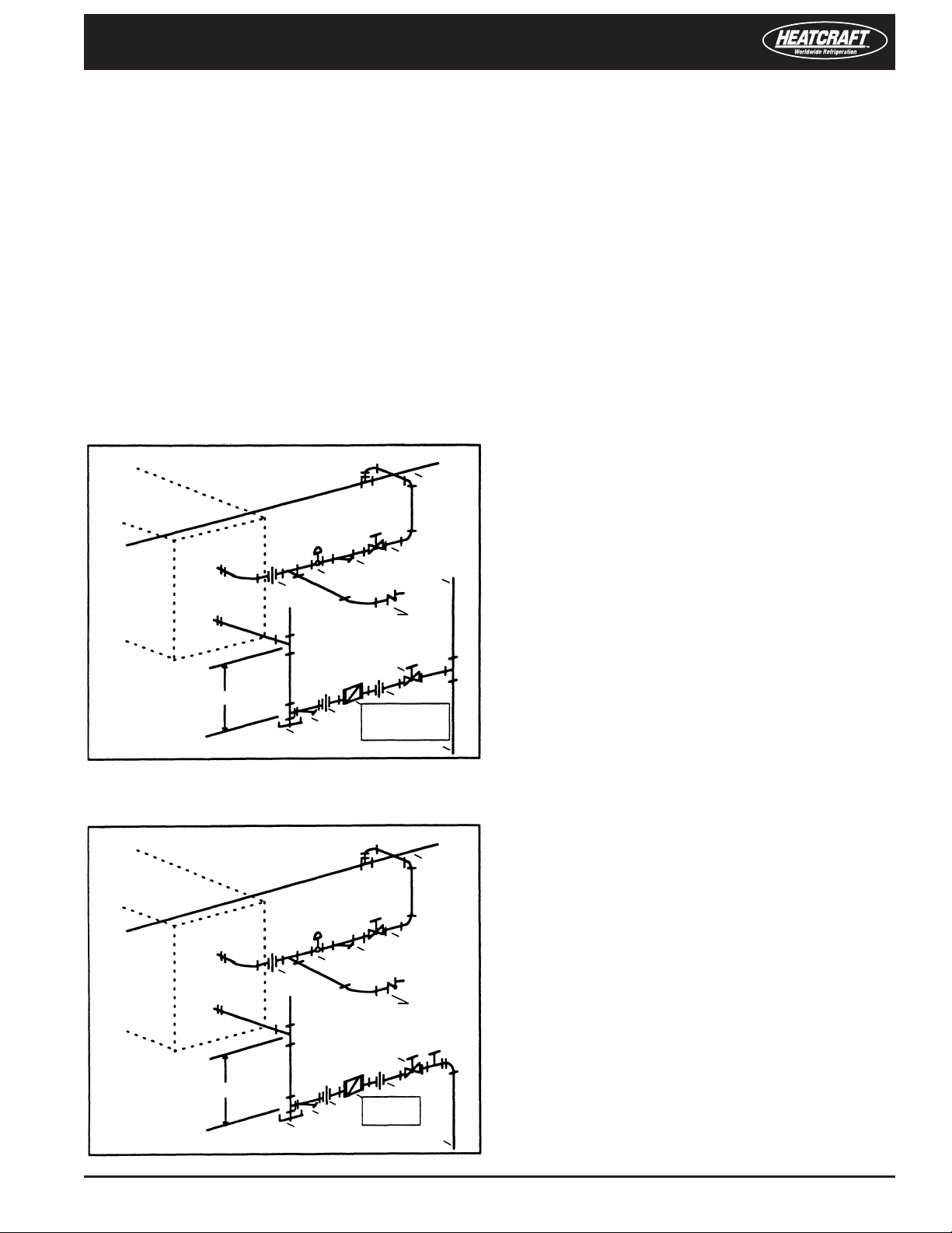
Diagrams 1 and 2 for controls positioning and piping
conguration�
When face and bypass dampers are used, it is good
practice to install a valve that closes with the face damper
to prevent overheating because of damper leakage or
heat from the exposed coil face�
Diagram 1� Typical Steam Coil Piping
Low Pressure, Open Gravity Return System
Steam Main
Water Piping
All piping must be supported independent of coils�
Swing joints or exible ttings must be provided to
absorb expansion and contraction strains� Rigid piping
may also reduce eectiveness of vibration isolators�
The water supply should always be connected to the
bottom inlet of the coil� The coil connections are
identied with stickers�
Water coils (3 through 10 rows) are supplied with a vent
and drain connection (1/4” MPT) that extends through
the unit casing� Coils must be adequately vented in order
to prevent air binding� For protection of coils exposed to
freezing temperatures, refer to page 6�
Direct Expansion
Both the liquid distributor and the suction line extend
through the casting� The expansion valve utilized must
be the external equalizer tube type� The expansion valve
bulb must be placed on the suction line between the
coil and the 1/4” external equalizer tube� Never put the
bulb in a trap�
Gate Valve
Strainer
Control Valve
Union
Vacuum Breaker
1/2”-15” Check Valve
Vent
Gate Valve
12” Minimum
Union
Strainer
Dirt Pocket
Union
Combination Float
and
Thermostatic Trap
Return Main
Diagram 2� Typical Steam Coil Piping
High Pressure System
Gate Valve
Strainer
Control Valve
Union
Vacuum Breaker
Vent
1/2”-15” Check Valve
Open Vent
Steam Main
All refrigerant piping practices should be in accordance
with local codes and latest ANSI Standard B9 Safety Code�
Hard-drawn type L or K copper tubing should be used�
Soft tubing may be used where bending is required,
provided it is in accordance with local codes�
Remember to check for adequate vacuum, clear tubes of
foreign material, etc�
Gate Valve
12” Minimum
Union
Strainer
Dirt Pocket
Union
Float or
Bucket Trap
Return Main
Air Handler Unit Installation & Operations Manual, August 2002 3
Page 4
Condensate Drain Trap
Installation and Operations Manual
Start-Up
Make sure all bolts and screws are tight� Remove tagged
shipping tie-down bolts and spacers from the fan and
motor assembly before start-up on internally isolated
units only�
Check the alignment of the sheaves and tighten the set
screws� Make sure that the dimension across the top
is equal on all grooves, otherwise excessive belt wear
will result�
Check for proper rotation of the blower pulley� Threephase motor rotation can be reversed by exchanging
two of the three leads at the motor starter� The rotation
of single-phase motors can be reversed by exchanging
leads inside the motor junction box�
(See motor wiring diagram�)
Check the amperage draw of the motor; should not
exceed the nameplate amps shown on the motor
serial plate�
After approximately two weeks of operation, the belts
will have almost reached their permanent stretch� At
this point, the belt tension should be checked again and
proper adjustment made�
Maintenance
The belt tension should be checked at threemonth intervals� The fan shaft bearings on sizes
03, 06, 08, 10 and 12 are lifetime-lubricated�
All other units have ball bearings that can
be re-lubricated�
Bearings mounted inside the fan section have extended
lubrication lines on the outside of the fan panels� The
suggested greasing intervals are indicated on a sticker on
the unit� It is recommended that bearings are lubricated
with a high quality lithium grease as indicated on the
sticker� Instructions are included on the motor nameplate
for lubricating the motor bearings�
The lter should be periodically inspected and replaced
or cleaned when necessary� Dirty lters inhibit air ow,
reducing the capacity of the system�
Condensate Drain Traps
The condensate drain trap piping must be properly
designed to ensure the removal of condensate� Incorrect
trapping can hold water, causing overow in the drain
pan� On blow-thru units with incorrect trapping, system
air can be lost down the drain�
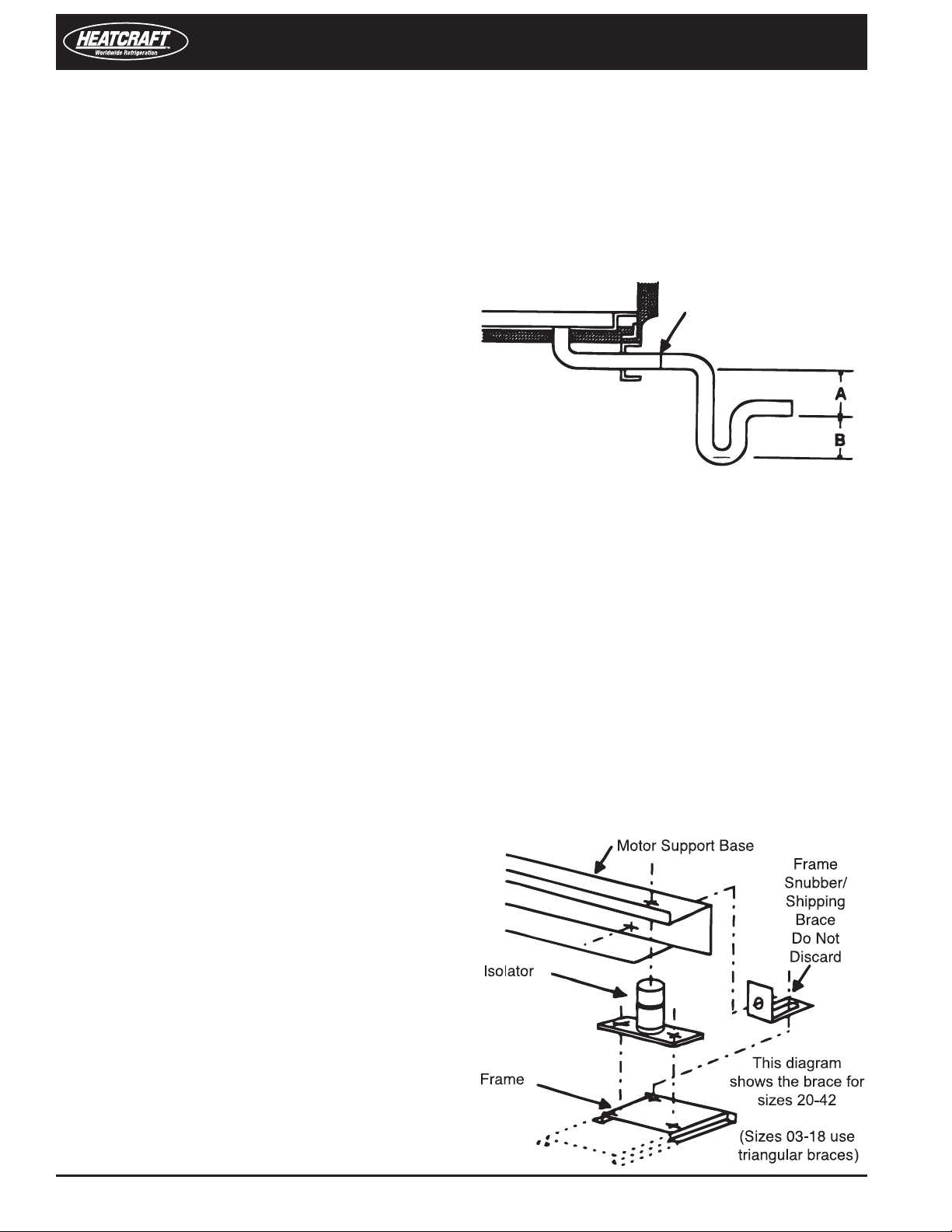
Figure 1�
(Air Seal)
1-1/4” Pipe Drain
(a) On draw-thru units (A) shall be equal to or
greater the coil section’s negative pressure at
operating conditions
(b) On blow-thru units (A) can be as small as 1” but
(B) must equal or exceed the total static pressure
in the coil section
Internally Isolated Units
Sizes 03-41 with optional internal spring isolation have
four hold-down shipping braces� Remove the 1/2” bolt
between each shipping brace and the motor base, then
loosen the bolt between the frame and brace and slide
the brace 5/8” from the motor support base� Re-tighten
the bolt so the shipping brace acts as a snubber on fan
start-up�
Figure 2�
Do not operate system without lters�
4 Part # 4346B001
Page 5
Air Handler Units
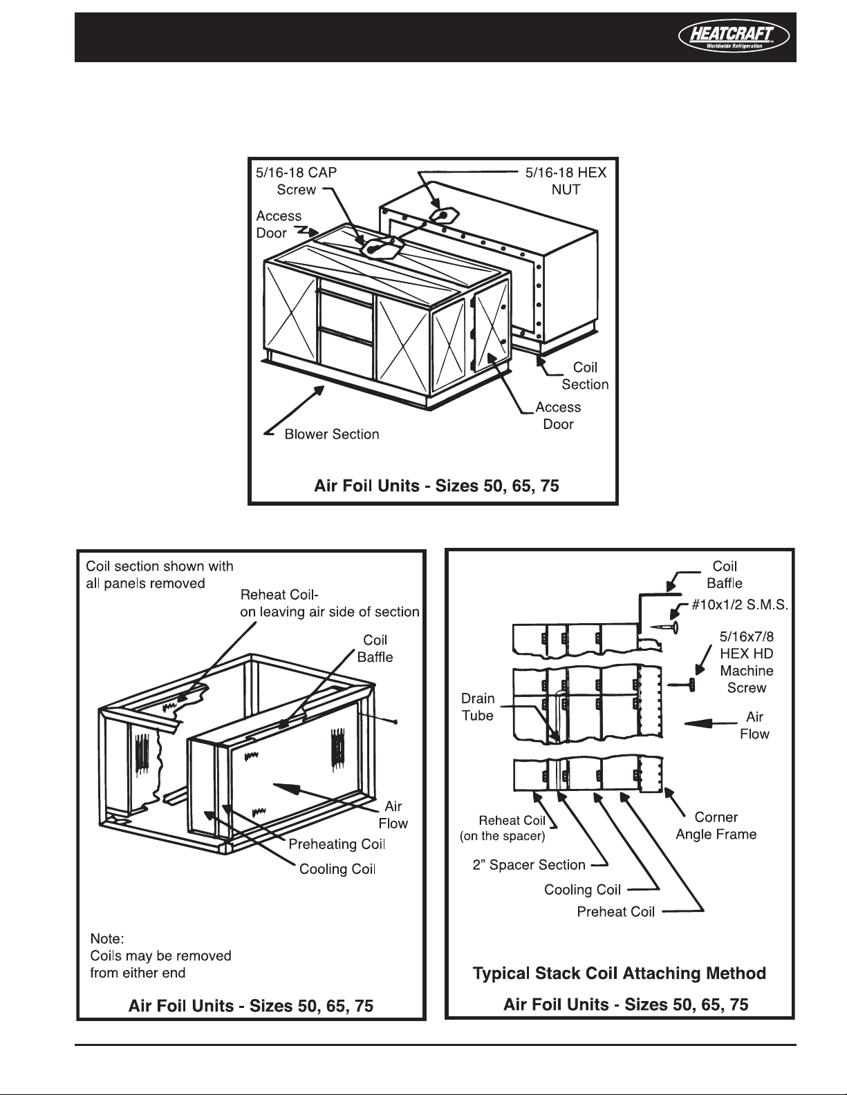
Typical ‘Accessory-to-Coil-Section’
and ‘Accessory-to-Accessory’ Attachment
Figure 3�
Figure 4� Figure 5�
Air Handler Unit Installation & Operations Manual, August 2002 5
Page 6
Installation and Operations Manual
Protecting Water Coils Exposed
to Freezing Temperatures
Water coils exposed to freezing temperatures must
be protected by properly draining the coils or adding
antifreeze solution to coils�
The coils are circuited so there are no trapped circuits�
However, because of the serpentine nature of the
circuiting, it is almost impossible to adequately drain the
coils with gravity alone� On longer coils, a fraction of a
degree deviation from a horizontal plane can lead to
trapped water within the circuits�
Water that failed to drain from a single tube, or even part
of a tube, can cause the tube to rupture upon freezing�
Draining Coils Using Supplemental
Air Blower
Ideally, a blower capable of delivering 150 CFM of air
at approximately 40-50 inches of water or more should
be used� Some small air compressors, while delivering
higher pressures, will not deliver sucient volume
of air�
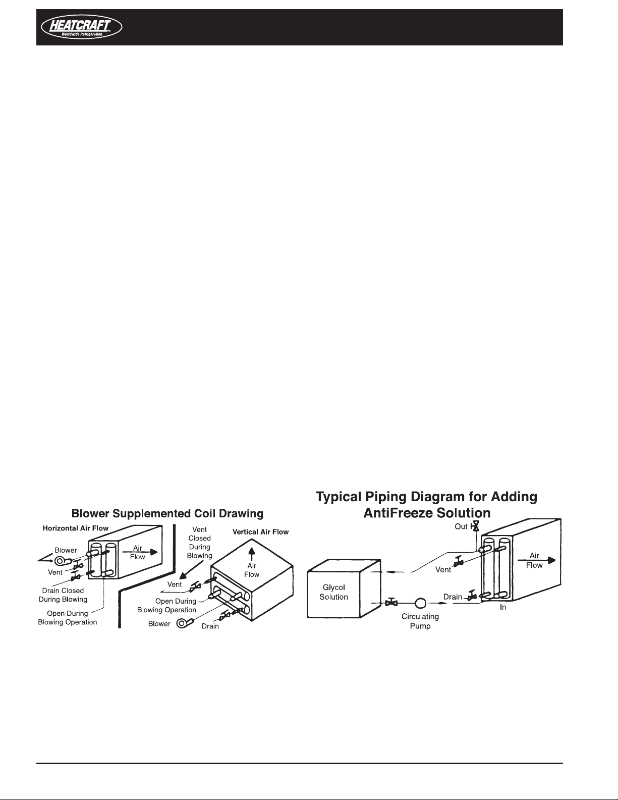
1� Drain the coils by gravity after opening the supply,
return, vent and drain connection� Tap the coil
causing along the length of the coil during the
draining process�
2� Connect the blower to a large connection at
the greatest elevation� The small vent or drain
connection on the header that the blower is
connected to should be closed� Refer to Figure 6 for
typical hook-up during the blow-out operation�
Installation of Antifreeze Solution
A second way to prevent a coil freeze-up is to add an
antifreeze such as glycol to the coil�
The addition of antifreeze to a system exposed to
freezing conditions may be necessary if the system must
be operational at a moment’s notice� Antifreeze aects
the chiller and coil performance and must be taken into
consideration when selecting the components�
Valve o the coil so only the coil has antifreeze added�
The best way to mix the antifreeze is to make a runaround loop with a circulating pump�
1� Open all connections and drain the coil as
thoroughly as possible�
2� The antifreeze solution should be added and
circulated until the solution is thoroughly mixed
and all air is purged from the coil� To accomplish
this the air vent should be opened during the
lling operation and cracked during the pumping
operation�
3� When the solution has circulated for 15-20 minutes,
the concentration of the solution should be checked
with a suitable hydrometer� If the concentration is
low, add more glycol and operate the pump again�
A typical piping diagram is shown in Figure 7�
4� The antifreeze solution may then be left in the
coils or drained and used to ush another coil�
The concentration must be checked for each
coil ushed�
Figure 7�
Figure 6�
3� Turn on the blower� The blower should be operated
until no moisture can be detected leaving the coil�
Then, shut the blower o and let the coil stand for
a few minutes, allowing the moisture on the walls
to accumulate�
4� Then the blowing-out operation should be
repeated� Ideally, the coil should stand 24 hours
and then be blown out again� Leave all connections
open until coil is put into operation�
6 Part # 4346B001
Note: Most antifreeze solutions will be furnished with
a concentration chart� Also, make sure the antifreeze
solution is not corrosive�
Page 7
Air Handler Units
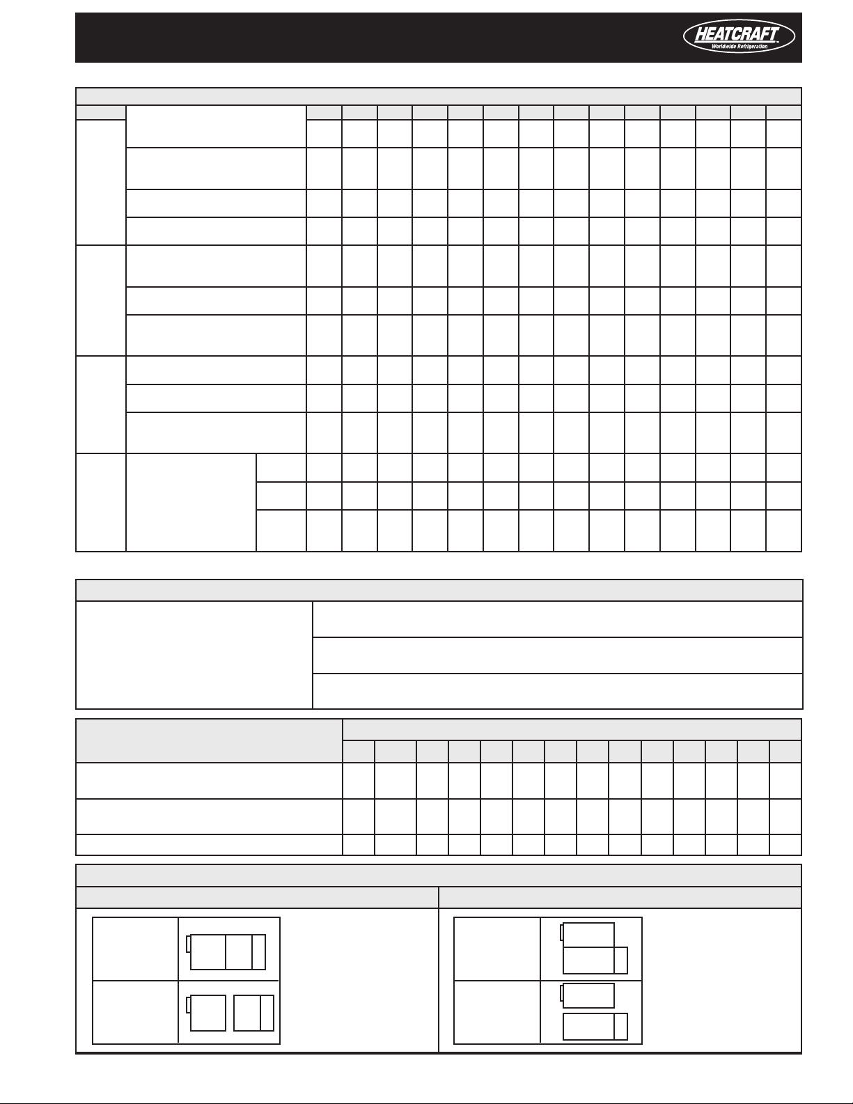
Air Handler Component Weight (lbs�)
Air Handler Component Unit Size
Section
Fan and Coil
Filter
Other
Large
Model ID
HDHDHeating Duty
Section
FO
FO
Section
Combination Filter & Economizer
Accessories
Coils
Description
S
S
L
L
V
High Capacity - TA & Pleated
High Capacity - Permanent
High Eciency - 21” Section
High Eciency - 28” Section
High Eciency - 44” Section
Internal Face and Bypass
External Face and Bypass
S Auxiliary Coil Module
L Auxiliary Coil Module
Short
Short
Long
Long
Vertical
Heating DutyFCAF
Fan Only
Fan Only
Flat - TA & Pleated 2”
Flat - Permanent 2”
Flat - Pleated 4”
Economizer
Electric Heater
5/8” Tube
(Type 5)
10 FPI
Fan
FC
AF
FC
AF
FC
FC
AF
12Row
34Row
6
8
10
03 06 08 10 12 14 18 20 26 34 41 50 65 75
290-430-500-550-650-790-816-836
318
450
553
600
-
-
73
79
88
95
-
482
83
89
98
187
196
112
143
173
216
403
204
257
454
134
168
240
311
383
296
387
170-280-312-360-450-510-564-605
162-266-296-342-428-485-536-575
60
66
75
149
168
155
176
82
103
121
127
150
174
195
323
363
525768757987100
129
164
157
184
223
356
Row36505680701018012094143
109
141
172
106
132
187
242
297
Row6478
Row
Row
Row
535
95
101
110
206
216
133
170
201
224
430
110
208
258
550
161
202
290
379
467
732
-
-
615
99
106
119
215
225
133
170
201
236
451
115
128
223
305
670
195
246
353
461
569
(Coil weight includes the weight of water when lled)
988
860
104
114
124
224
234
153
196
230
247
471
138
155
306
504
774
106
164
223
282
408
534
659
968
1,188
946
1,177
1,033
1,067
-
-
1,004
106
126
126
230
240
175
225
264
254
484
148
166
280
497
954
110
169
231
292
422
552
682
1,177
1,111
715
679
108
135
127
234
244
180
224
274
260
494
155
175
261
492
1,104
112
173
236
299
432
565
699
1,221
1,430
1,254
693
891
658
846
115
165
130
244
254
194
246
299
300
544
180
200
310
563
1,434
144
228
314
398
578
760
942
1,386
1,518
1,782-2,700-3,300-4,496
1,474
1,672
1,793
2,057
1,628
1,881
902
1,078
1,221
1,474-2,600-3,200-3,359
857
1,024
1,160
1,400-2,470-3,040-3,191
160
185
240
275
185
210
260
290
365
450
235
248
296
318
358
380
430
550
690
840
260
350
286
385
331
362
617
648
1,760
2,118
195
239
318
396
444
557
569
718
830
1,052
1,092
1,385
1,355
1,718
-
2,850
-
255
390
298
360
520
269
345
412
680
1,040
420
462
515
665
2,481
339
562
737
913
1,278
1,638
2,194
-
3,480
-
315
460
351
440
650
330
425
516
800
1,240
520
650
640
820
3,143
406
673
936
1,199
1,677
2,154
2,893
-
4,690
-
384
560
428
535
790
359
463
552
975
1,510
634
793
1,305
1,499
3,599
538
891
1,168
1,445
2,017
2,589
3,478
To Estimate Weights For Other Coils
For 1/2” Tube (Type A): Multiply Type 5 coil weight by 0�800
For small coil: Multiply large coil weight by 0�823
TA = Throwaway lters
AF = Airfoil Fan
FC = Forward Curved Fan
For 14 FPI: Multiply 10 FPI coil weight by 1�121
For 12 FPI: Multiply 10 FPI coil weight by 1�065
For 8 FPI: Multiply 10 FPI coil weight by 0�935
For 6 FPI: Multiply 10 FPI coil weight by 0�915
Air Handler Motor
and Drive Weight (lbs�)
Open Single Speed Motor
Totally Enclosed Fan Cooled (TEFC)
High Eciency Open Single Speed
Open 2 Speed, 2 Winding
1 1�5-2 3 5 7�5 10 15 20 25 30 40 50 60 75
555665718688105
67717497114
115
Motor Horsepower, 1800 RPM
172
193
253
286
104
178
194
275
336
127
209
216
341
384
160
291
267
368
356
348
400
529
411
461
624
396
427-621-623--
366
600
670
T - Frame Size 143 145 182 184 213 215 254 256 284 286 324 326 364 365
Central Station Air Handler, Shipment of Assemblies - Basic Unit
Horizontal Style Units, Fan, Coil, Flat Filter Section Vertical Style Units, Fan, Coil, Flat Filter Section
S, L, FO,
HD Sizes
03 – 18
S, L, FO,
HD Sizes
20 – 75
FS
FS
CS
CS
These diagram show
typical shipments�
Some set-ups may vary
FF
with certain units�
Consult the factory if
you require a specic
assembly shipped in a
FF
special way�
V Sizes
03 – 18
V Sizes
20 – 41
FS
CS
FS
CS
We ship high capacity
and high eciency
lter sections,
FF
economizers, dampers
and electric heat
sections separately�
FF
720-828
-
-
-
-
Air Handler Unit Installation & Operations Manual, August 2002 7
Page 8
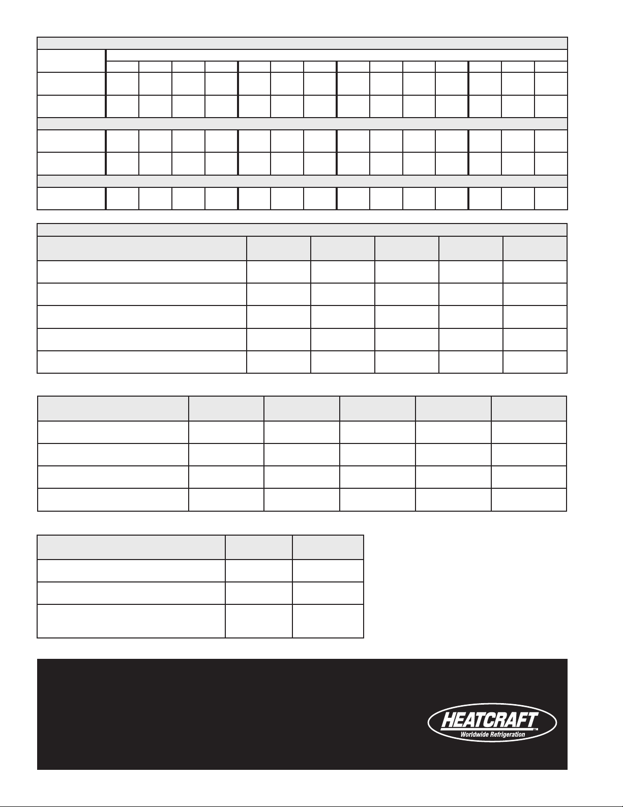
Quantity and Dimensions of Filters for Flat Filter Section
Filter
Dimensions
2” x 16” x 20”
2” x 20” x 20”
2” x 16” x 25”
2” x 20” x 25”
03 06 08 10 12 14 18 20 26 34 41 50 65 75
1
1
-
-
-
-
-
2
2
2
-
-
4
-
3
3
-
-
Air Handler Unit Size
1
1
2
2
2
2
2
2
6
4
-
-
4
8
-
-
-
4
8
12
6
-
-
7
-
14
-
High Capacity Filter Section
2” x 16” x 20”
2” x 20” x 20”
2” x 16” x 25”
2” x 20” x 25”
2
2
-
-
-
-
-
4
-
6
-
-
2
4
-
-
8
-
-
4
4
-
6
4
-
4
6
10
-
2
20
4
-
-
20
-
-
4
-
-
-
30
High Eciency Filter Section
24” x 24”
12” x 24”
1
1
2
-
2
2
2
3
2
3
3
3
6
-
4
4
5
10
5
10
-
15
5
-
Replacement Parts - Note: Conrm the shaft diameter when ordering parts
Sizes 03-12 Forward Curved,
Fan Diameter, Type
03 FC
03 FC
06 FC
06 FC
08 FC
08 FC
10 FC
10 FC
12 FC
12 FC
NOTES: For sizes 03-12, it is less expensive to replace the blower assembly than to replace the blower wheel� Blower assembly also includes bearings and shaft
9”
9”
12”
12”
15”
15”
18”
18”
18”
18”
Low Pressure
Med� Pressure
Low Pressure
Med� Pressure
Low Pressure
Med� Pressure
Low Pressure
Med� Pressure
Low Pressure
Med� Pressure
Shaft
Diameter
3/4”
1”
1”
1-3/16”
1”
1-3/16”
1”
1-3/16”
1”
1-3/16”
Bearing
Part No�
4215V
4352N
4350N
4353N
4350N
4353N
4350N
4353N
4350N
4353N
Bearing
Type
Cartridge
Pillow Block
Cartridge
Pillow Block
Cartridge
Pillow Block
Cartridge
Pillow Block
Cartridge
Pillow Block
Shaft
Part No�
4317Z
4343N
4318Z
4344N
4319Z
4345N
4320Z
4346N
4320Z
4346N
8
20
-
-
-
12
30
15
3
Blower
Assembly
4317M
4322M
4318M
4323M
4319M
4324M
4320M
4325M
4320M
4325M
4
10
4
10
-
14
35
20
4
Sizes 14-41 Forward Curved,
Fan Diameter, Type
14 FC
14 FC
18 FC
18 FC
20 FC
26 FC
34 FC
41 FC
NOTES: For sizes 14-41 forward curved fans, it is less expensive to replace the blower wheel than to replace the blower assembly
20”
20”
20”
20”
22”
22”
25”
30”
Low Pressure
Med� Pressure
Low Pressure
Med� Pressure
Med� Pressure
Med� Pressure
Med� Pressure
Med� Pressure
Sizes 26-75, Air Foils
Unit Size, Fan Diameter, Type
20 AF
26 AF
34 AF
41 AF
50 AF
65 AF
75 AF
18-1/4”
18-1/4”
24-1/2”
30”
32-3/8”
39-3/8”
39-3/8”
Med� Pressure
Med� Pressure
Med� Pressure
Med� Pressure
Med� Pressure
Med� Pressure
Med� Pressure
Shaft
Diameter
1-3/16”
1-3/16”
1-3/16”
1-3/16”
1-7/16”
1-7/16”
1-11/16”
1-15/16”
Shaft
Diameter
1-7/16”
1-7/16”
1-15/16”
2-3/16”
2-7/16”
2-11/16”
2-11/16”
Pillow Block
Bearing
4353N
4353N
4353N
4353N
5562N
5562N
5563N
5564N
Pillow Block
Bearing
5562N
5562N
5564N
5521T
5597T
5875E
5875E
Shaft
Wheel
4342N
4342N
4342N
4342N
4522R
4522R
4525R
4500S
For size 41-75 air foils and parts other than
bearing replacement, call the parts department,
800-686-7278, with air handler model number
Heatcraft Refrigeration Products can then advise
the correct blower assembly description for you�
Visit our website at www�heatcraftrpd�com for technical literature online�
Blower
Wheel
5154E
5154E
5154E
5154E
5153E
5153E
5179D
5178D
Part of housing
Part of housing
Part of housing
Part of housing
Air Foil Note:
and discharge arrangement�
Blower
Cut-O
4418T
4418T
4419T
4421T
Heatcraft Refrigeration Products LLC
2175 West Park Place Blvd�, Stone Mountain, GA 30087
Ph�: 770�465�5600 • Fax: 770�465�5990 • www�heatcraftrpd�com
Rev 0407
H-IM-AH-0407 | version 000
Since product improvement is a continuing eort, we reserve the right to make changes in specications without notice�
 Loading...