

Page 1
H-IM-76
Part #25005501
September 2000
Replaces: O&I 10107C
I&O Remote Fluid Coolers, #2508404
H-IM-44A, #2500030
FLUID COOLERSFLUID COOLERS
FLUID COOLERS
FLUID COOLERSFLUID COOLERS
INSTALLATION, OPERATION & MAINTENANCE INSTRUCTIONSINSTALLATION, OPERATION & MAINTENANCE INSTRUCTIONS
INSTALLATION, OPERATION & MAINTENANCE INSTRUCTIONS
INSTALLATION, OPERATION & MAINTENANCE INSTRUCTIONSINSTALLATION, OPERATION & MAINTENANCE INSTRUCTIONS
Heatcraft Refrigeration Products Division
2175 West Park Place Blvd., Stone Mountain, GA 30087
(770) 465-5600 • Fax: (770) 465-5990
HEATCRAFT REFRIGERATION PRODUCTS
www.heatcraftrpd.com
1
Page 2
GENERAL DESCRIPTION
The Fluid Cooler units are designed for cooling fluids such as 40%
Ethylene Glycol. These units are for remote use and use direct
drive, permanently lubricated fan motors. Each module is separated by a baffle to prevent air bypass. The basic unit is completely
factory wired to its electrical junction panel. Provisions are provided for terminal block wiring of main power, as well as, optional
accessories. Please read the instructions carefully before starting
the installation.
INSPECTION
Inspect the unit to make sure there is no shipping damage before
beginning the installation. If damages are found it should be
reported to the carrier.
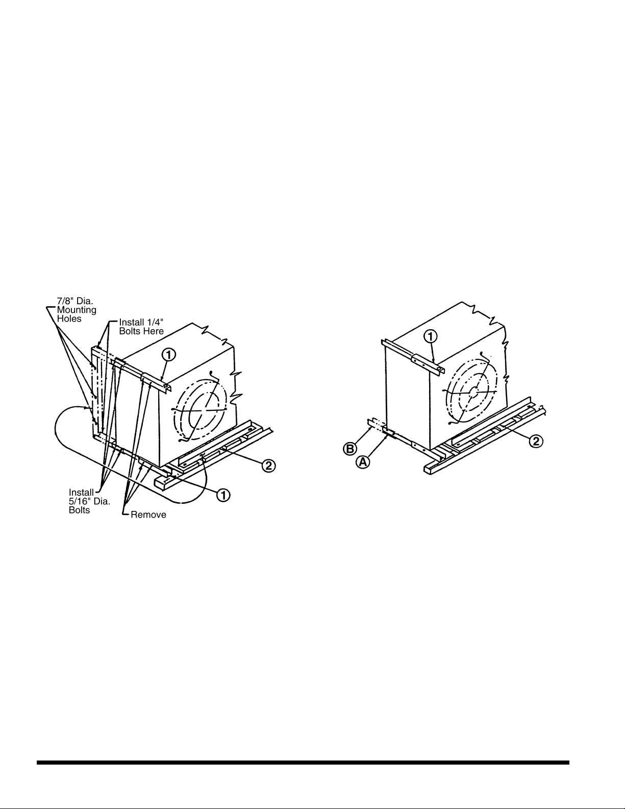
FIGURE 1
MOUNTING
Models 005 through 026, can be mounted for either horizontal or
vertical air flow. Refer to Figure 1 for leg assembly mounting for
horizontal and vertical air flow units respectively. The unit should
be mounted onto a level base or frame that is strong enough to
sustain the unit's weight plus its operating charge. The base or
frame and necessary hardware for securing the unit is the
responsibility of the installing contractor. All mounting holes
provided must be used. Unrestricted air flow and unit accessibility
for service are prime concerns in locating these fluid coolers.
LEG ASSEMBLY FOR VERTICAL AIR FLOW
INSTALLATION
1. Remove bolts securing condenser skid.
2. Remove leg extensions (#1) by removing four 5/16" x
3-1/2" bolts.
3. Install as shown in dotted lines with same four bolts.
4. Install mounting angle (#2) as shown (dotted lines) with
four 1-20 x 3/4" bolts provided.
5. Condenser can be hoisted by the 1-1/2" holes in leg
assemblies.
LEG ASSEMBLY FOR HORIZONTAL AIR
FLOW INSTALLATION
1. Remove bolts securing condenser skid.
2. Remove piece (#1) and attach to rear of bottom leg at
"A" to complete mounting base. Piece (#2) is not
required in the horizontal discharge application and
may be discarded.
3. Condenser can be hoisted by the 1-1/2" holes in leg
assemblies.
4. Attach unit to base using mounting holes on leg extensions at "B".
6. Attach condenser to base using 7/8" diameter holes in
the base angle.
2 H-IM-76
Page 3
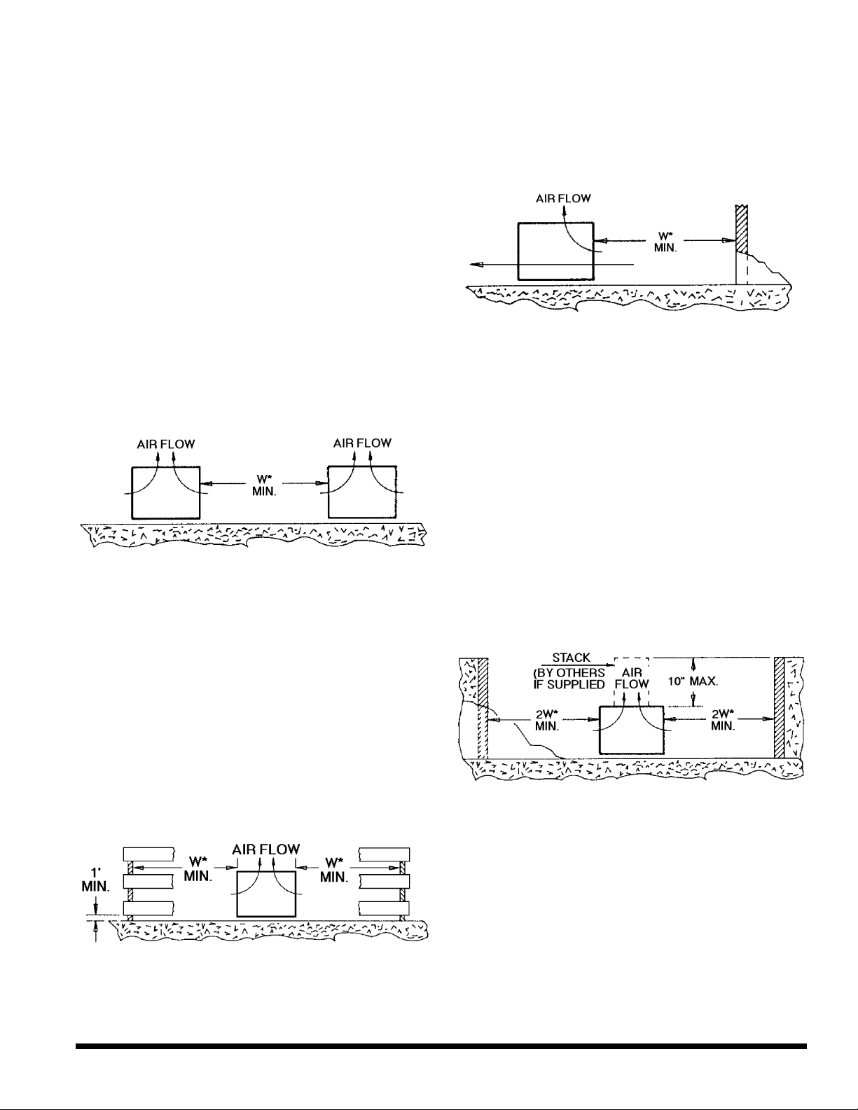
SPACE & LOCATION REQUIREMENTS
Walls or Obstructions
The unit should be located so that air may circulate
freely and not be recirculated. For proper air flow and
access all sides of the unit should be a minimum of “W”
away from any wall or obstruction. It is preferred that
this distance be increased whenever possible. Care
should be taken to see that ample room is left for
maintenance work through access doors and panels.
Overhead obstructions are not permitted. When the unit
is in an area where it is enclosed by three walls the unit
must be installed as indicated for units in a pit.
Multiple Units
Units in Pits
The top of the unit should be level with the top of
the pit, and side distance increased to “2W”.
If the top of the unit is not level with the top of pit,
discharge cones or stacks must be used to raise
discharge air to the top of the pit. This is a minimum
requirement.
For units placed side by side, the minimum
distance between units is the width of the largest unit. If
units are placed end to end, the minimum distance
between units is 4 feet.
Decorative Fences
* “W” = Total width of the fluid cooler.
HEATCRAFT REFRIGERATION PRODUCTS
Fences must have 50% free area, with 1 foot
undercut, a “W” minimum clearance, and must not
exceed the top of unit. If these requirements are not
met, unit must be installed as indicated for “Units in
pits”.
3
Page 4

SYSTEM INSTALLATION
NOTE: All installation and maintenance are to be
performed only by qualified personnel who are
familiar with local codes and regulations, and
experienced with this type of equipment.
CAUTION: Sharp edges and coil surfaces are a
potential injury hazard. Avoid contact with them.
General
1. Structure supporting unit must be designed to
support both the unit and the fluid. Table 1 provides
weight of fluid per gallon. Table 5 provides unit
weight and volume data. Provide suitable flashing
of the roof, if this is a roof installation. For ground
level mounting, a concrete pad is recommended.
Mounting holes permit the unit to be bolted down to
withstand wind pressures. Provide adequate
clearance for unobstructed air flow to coils. Also
see "Space and Location Requirements".
Table 1. Fluid Weight Per Gallon
Percent Glycol Pounds Per Gallon
0 (Water) 8.345
10 8.395
20 8.495
30 8.604
40 8.712
50 8.804
2. Level mounting is necessary to assure proper fluid
distribution through the coil as well as flooded
suction for the pump.
3. Water piping must comply with local codes. Correct
pipe sizing will help reduce pumping power and
operating costs.
4. In case of doubt, consult the manufacturer for the
dry cooler fluid pressure drop at the specific
conditions on your job.
5. Provide sufficient valves and unions to permit easy
access to parts subject to wear and possible repair
or replacement.
6. After fluid piping is completed, all joints should be
leak tested.
7. Where city water makeup is required, follow local
codes, making certain that disconnecting provisions
are provided.
8. Select wire in accordance with nameplate data and
local codes.
Piping Installation
The piping system should provide maximum leak
prevention. Weld or sweat joints should be used where
possible or tightly drawn Teflon tape threaded pipe joints
should be made if needed. The fact that glycol solutions
or other heat transfer fluids will leak where water will not,
must be taken into account.
The glycol system should not employ a pressure
reducing valve. This is because a slight leak would lead
to dilution of the mixture. Any refill should be controlled
so as to maintain the proper glycol-to-water ratio.
Table 2 shows pressure drops for various pipe
sizes at flow rates commonly used with a typical dry
cooler. These pipe sizes are not necessarily always
correct for the run from the condenser to the dry cooler.
Proper pipe size will depend on available pump head.
This can be determined by subtracting from the total
available pump head at design flow, the condenser
pressure drop (Table 3) and the dry cooler pressure
drop. Allow some safety factor for last minute pipe
fittings added to the system and for eventual fouling of
the system.
a. Glycol piping requires no insulation except when
fluid temperature will be below ambient dewpoint
temperatures. Dry coolers normally produce about
70° or higher fluid temperatures.
b. Vents are required at all high points in the piping to
bleed air when filling the system. If fluid coolers are
at high points, vent valves should be installed at
each fluid cooler.
c. It is recommended that gate valves be installed on
both sides of the pump to prevent loss of fluid in the
event the pump should require repair or
replacement. Shut-off valves are also
recommended at water cooled condensers in case
the condensing unit is to be moved or requires
maintenance involving the coolant system.
Table 2. Pressure Loss in Feet of Water
Pipe
Flow Size O.D. Head Ft./100 Ft. Head Ft./100 Ft.
GPM Steel Copper Equiv. Length Equiv. Length
15 1 1 1/8 17.6 15.0
20 1 1 1/8 30.2 23.1
25 1 1 1/8 - 34.6
25 1 1/4 1 3/8 11.5 12.6
30 1 1/4 1 3/8 16.3 17.4
35 1 1/4 1 3/8 21.8 23.0
40 - 1 3/8 - 26.3
40 1 1/2 1 5/8 13.0 12.9
45 1 1/2 1 5/8 16.5 15.7
60 - 1 5/8 - 26.3
60 2 2 1/8 7.9 7.0
80 2 2 1/8 13.7 12.0
100 2 1/2 2 5/8 8.5 6.1
150 2 1/2 2 5/8 18.6 12.9
200 3 3 1/8 10.7 9.1
250 3 3 1/8 16.5 13.7
300 3 1/2 3 5/8 11.1 9.2
300 4 4 1/8 5.9 4.9
350 4 4 1/8 7.9 6.5
400 4 4 1/8 10.2 8.2
Type "L" Schedule 40 Steel Copper Tube Head
4 H-IM-76
Page 5

Table 3.
SYSTEM INSTALLATION
Pressure
Model BTUH Loss
CFM 30
5 5050 74200 49000 15 4.6
8 6450 121500 80200 25 8.5
10 10100 162200 107100 35 11.1
12 12400 186800 123300 40 14.0
14 13700 223100 147200 45 21.3
16 12900 250300 165200 50 15.4
21 20500 319900 211100 65 8.9
23 19900 340800 224900 70 10.1
26 19400 389400 259600 100 11.2
1
At 130° entering liquid, 100° entering air
2
At 115° entering liquid, 95° entering air
°TD
1
20°TD
2
GPM Ft. H2O
Glycol manufacturers offer a specially inhibited glycol
(formulated for snow melting systems) which does not
1
react with zinc. This glycol is also suitable for heat
transfer systems. Glycol manufacturers also provide
inhibitor check services on a regular basis.
Consequently, good glycol system design requires the
following precautions:
1. No galvanized piping is to be used.
2. System piping must be thoroughly cleaned and
3. No chromate inhibitor treatment must be used.
4. The glycol manufacturer should provide inhibitor
Glycol Charge
The amount of ethylene glycol required depends upon
the following:
a. The holding volume of the system which includes the
holding capacity of the condenser, the holding
capacity of the interconnecting piping and the
holding capacity of the dry cooler.
Fluid Circulating Pump
Mechanical seal type pumps must be used for glycol
systems. Gland type pumps would cause glycol waste
and, if used with a pressure reducing valve, will lead to
dilution of the glycol mixture and eventual freeze-up.
b. Percentage of glycol required by volume to provide
protection at the design minimum outside
temperature (see Table 4).
Pump is selected for piping friction loss plus fluid
pressure drop through the dry cooler coil, plus pressure
drop through the heat source.
lift
Table 4. Percentage of Ethylene Glycol to
is made since in a closed system a counterhead acts
on the pump suction.
be Added by Volume
With glycol solution the pump performance curve will
Percent % 20% 30% 40% 45% 50%
Minimum Outside Design
Temperature °F
+15 -3 -14 -23 -38
Table 4 is intended to be used as a guide only. Proper
precautions need to be taken to prevent freeze damage during
low ambients. Consult glycol vendor recommendations for
specific freeze protection for your location.
Glycol Sludge Prevention
Glycol systems may be subject to sludge formation
in coils, due to one or more of the following causes:
1. Reaction of the corrosion inhibitor with galvanized
piping (zinc).
2. Reaction of the glycol with chromate type water
additives.
3. Reaction of the glycol with pipe dope, cutting oils,
solder flux, and other system dirt.
drift to the right from its design point, due to differences
in circuit design, control valve application, pressure drop
calculations, etc. The pump should be selected high on
the curve so as to provide for the "drift". The pump
curve should be "flat" so that the pump will compensate
for our inability to exactly predict the final operating
system flow condition and to provide sufficient flow for
satisfactory heat transfer and maximum protection
against freezing at the far end of the circuit. The pump
motor should have sufficient power for operating over
the entire pump curve to prevent motor overload at
reduced voltages. Paralleled pumps can also be used
for good power economy and continuous and automatic
standby operation. Properly applied parallel pumps will
guard against system breakdown caused by a simple
pump failure. Certain older systems have nonoperating
standby pumps of equal capacity to the operating unit.
We recommend parallel pumps in continuous operation
because they provide practically the same type of
standby, in addition to being completely automatic, at
lower initial and operating cost.
flushed with a heated trisodium phosphate solution
before filling with the water/glycol mixture.
check service and supply additional inhibitor as
required.
No allowance for vertical
HEATCRAFT REFRIGERATION PRODUCTS
5
Page 6

START-UP
1. Prestart:
Check for correct dry cooler fan rotation. This can be
done by quickly jogging the fan contactor. Be sure
that the fans run freely. The same check is
recommended for pumps.
Mixing Glycol and Water
Regardless of the strength of the mixture, you MUST
pre-mix the glycol and water prior to adding it to the
system. The chemical reaction between the two will
release oxygen, which is extremely undesirable in a
close-loop system.
WARNING: For dry coolers operating without
glycol mixture, adequate freeze
protection is necessary during
ambients below 32° F.
2. Filling and Purging the System
The system should be pressure tested before adding
glycol. The system can be tested with air or water,
however if the ambient temperature is at or below
freezing the use of air is recommended. Test
pressure should not exceed 60 PSIG.
a. Roof Mounted Fluid Cooler
To fill the system pour the premixed water and
glycol into the expansion tank. Fill the system
until theexpansion tank is half full, then purge
the air from ALL vents. Operate the system for a
minute, then purge ALL vents again, and add
glycol as required. Repeat the purging of all
vents after the first hour of operation and again
after several hours of operation.
b. Ground Mounted Fluid Cooler
The fluid cooler may be lowest point in the
system,consequently the premixed water and
glycol will have to be pumped into the system.
Close the shut off valve and open the two hose
bibbs installed in the piping run on the leaving
side of the pump, see Piping Diagram 1.
Connect a pump and hose to the hose bibb away
from the pump and a hose to the hose bibb closest
to the pump. Begin pumping the glycol mixture into
the system at FULL PRESSURE. For the return
hose you should close the hose bibb so that you
get only a small flow of fluid or air. This is necessary
so you will build a head of fluid which will force the
air from the system. Once all the air is out you will
have a steady flow of only fluid. At this joint you
should close off the two hose bibbs and open
the shut off valve. See Diagram 1.
3. Flow Adjustment Procedure:
Once the system is completely full of fluid, start the
fluid circulating pump. To assure proper fluid flow,
adjust the shut-off valve for required GPM by
checking pump curve and observing gauge
pressure, or by using an in-line flow meter.
4. Instruction Envelope:
Keep wiring diagrams, instructions, list of spare
parts, in an envelope within easy reach of the
installed dry cooler.
Diagram 1.
6 H-IM-76
Page 7

Models 005-026
SPECIFICATIONS
VERTICAL AIR FLOW
HORIZONTAL AIR FLOW
Table 5.
Maximum Motor Connections Approx. Internal
Model Fan Circuits Data ODS Net Wt. Volume
No. A B CFM No. Dia. Available HP
5 39-3/4 30 5,050 1 24 8 1/3 3.5 1/3 2.6/1.3 1-3/8 1-3/8 180 2.7
8 49-3/4 40 6,450 1 26 16 1/2 4.1 1/3 2.6/1.3 1-5/8 1-5/8 260 3.8
10 69-3/4 60 10,100 2 24 16 1/3 7.0 1/3 5.2/2.6 2-1/8 2-1/8 450 4.0
12 69-3/4 60 12,400 2 26 16 1/2 8.2 1/3 5.2/2.6 2-1/8 2-1/8 470 4.0
14 89-3/4 80 13,700 2 26 16 1/2 8.2 1/3 5.2/2.6 2-1/8 2-1/8 510 4.9
16 89-3/4 80 12,900 2 26 32 1/2 8.2 1/3 5.2/2.6 2-1/8 2-1/8 530 6.1
21 129-3/4 120 20,500 3 26 24 1/2 12.3 1/3 7.8/3.9 2-5/8 2-5/8 550 6.6
23 129-3/4 120 19,900 3 26 24 1/2 12.3 1/3 7.8/3.9 2-5/8 2-5/8 580 6.6
26 129-3/4 120 19,400 3 26 32 1/2 12.3 1/3 7.8/3.9 2-5/8 2-5/8 625 8.4
1
FLA
1
HP
2
FLA
2
Inlet Outlet (Lbs.) (Gal.)
1 Motor
voltage 208/230/1/60; 1075 RPM
2 Motor
voltage 208/230/460/3/60; 1140 RPM
HEATCRAFT REFRIGERATION PRODUCTS
7
Page 8

Diagram 2. Typical Wiring Diagram for
208-230/1/60
Models 5-8
Models 10-16
Models 21-26
Diagram 3. Typical Wiring Diagram for
208-230-460/3/60
Models 5-8
Models 10-16
Models 21-26
Diagram 4. Typical Wiring Diagram for
208-230/1/60 with Fan Cycling.
Diagram 5. Typical Wiring Diagram for
208-230-460/3/60 with Fan Cycling.
* CONTROL CIRCUIT: May be 24 volt, 120 volt, or 230 volt (as specified).
WIRING
All electrical wiring must be done in accordance with National Electrical code and local codes. See unit data plate for FLA and Maximum
Overcurrent Protection Rating. Electrical knockouts are provided for ease of wiring to the main power terminal block of the unit, as well
as, any optional accessories that may be part of your unit. For the wiring of your specific model refer to the wiring diagram located inside
the electrical junction box.
The Fluid Coolers are available with 208/230 volt, single phase or 208/230/460 volt three phase fan motors. Refer to the unit data plate
for the operating voltage of your specific unit.
We reserve the right to make changes in specifications or design, at any time, without
notice and without liability to purchasers or owners of previously sold equipment.
8 H-IM-76
 Loading...