

Page 1
Air Cooled Condensers
Model DVT 1 Through 23 Tons
Bulletin 7150E
October, 2004
(Replaces 7150D • 12/99)
Specification Data
Page 2
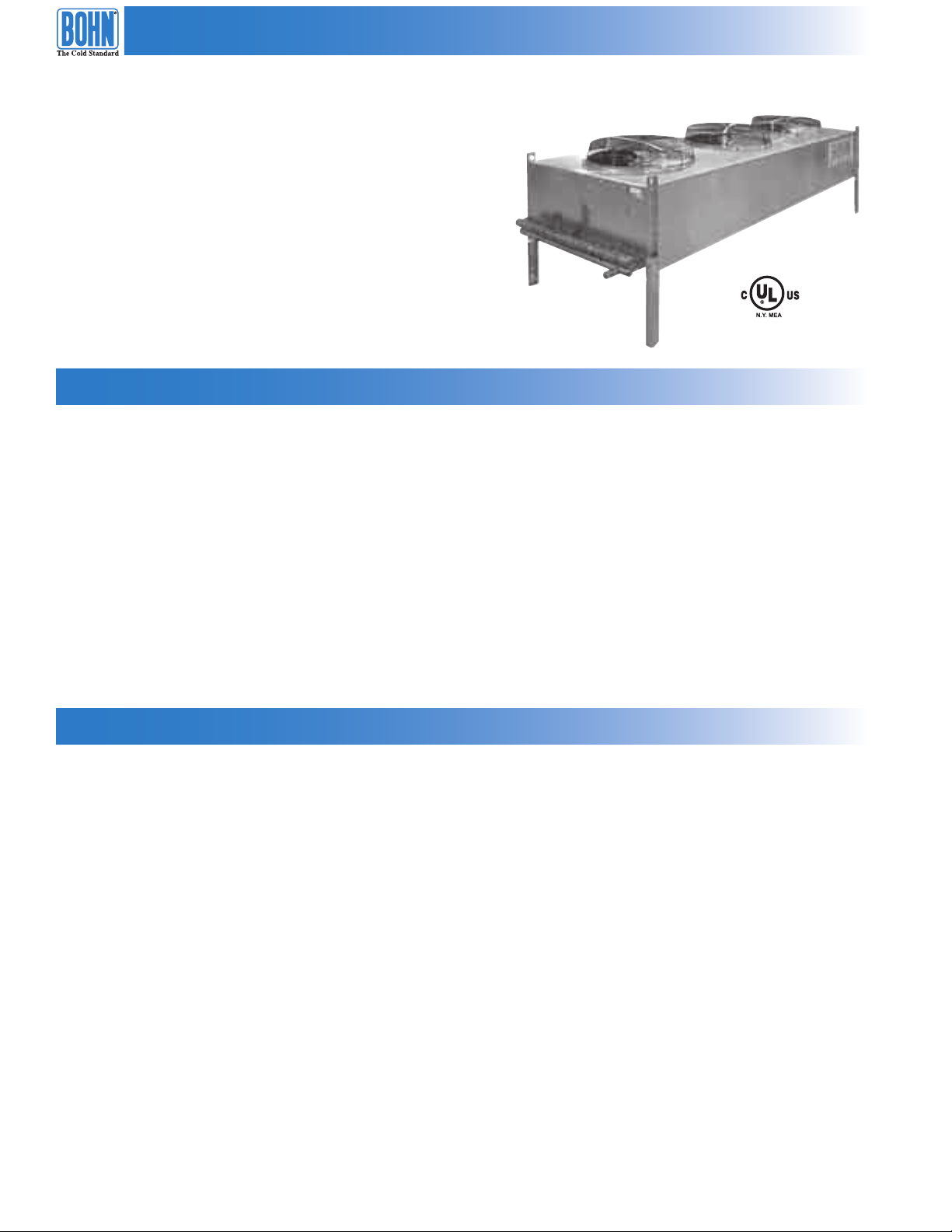
Model DVT Air Cooled Condensers
DVT air cooled condensers are available from one through
23 ton models. They are designed for efficient performance
and low maintenance.
Design Features
• Horizontal or vertical air discharge.
• Attractive aluminum housing.
• Multicircuiting at no additional charge.
• Coated steel fan guards.
• Energy efficient fan motors with internal overload protec tion and permanently lubricated
ball bearings.
• Motors wired to a common junc tion box.
• Fully baffled fan sec tions to prevent windmilling.
• UL listed.
• CUL Canada.
Available Options
®
• Limitizer
• Ambient or pressure activated fan cycling.
• Optional coils including Heresite
• Single phase fan motors available on all models.
• Three phase motors available on models 005 - 023.
• 575/3/60 motors available on models 005 - 023.
• Sealtite wiring on models 005 - 023.
• Variable speed fan cycling.
head pressure control.
®
coated, BohnGuard™, and all copper coils.
2
© 2004, Heatcraft Refrigeration Products LLC
Page 3
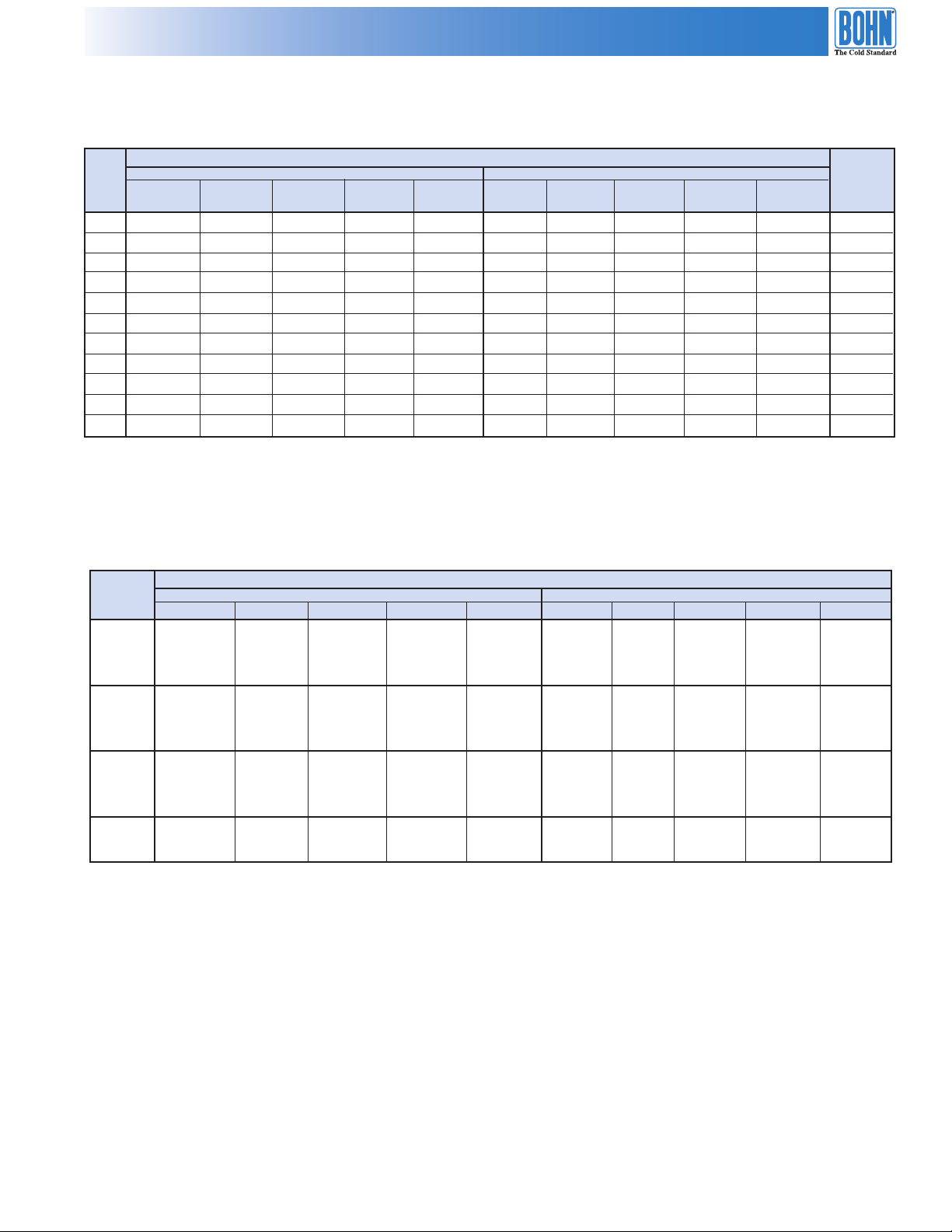
Condenser Performance
Table 1. Performance Data for 60 Hz.
Total Heat of Rejection, MBH / kcal/hr
R404A/R507 R22 Maximum
DVT 1˚F T.D. 10˚F T.D. 15˚F T.D. 20˚F T.D. 30˚F T.D. 1˚F T.D. 10˚F T.D. 15˚F T.D. 20˚F T.D. 30˚F T.D. Circuits
Model
001 0.74 340 7.5 2,000 11.2 2,700 15.0 4,100 22.4 5,800 0.76 350 7.6 2,100 11.4 2,800 15.3 4,200 22.9 5,900 1
002 1.00
003 1.54
005 2.38
008 3.92
010 4.77
012 5.96
014 6.85
016 7.83
021 10.29
023 11.07
Notes: For R134a, multiply R22 capacity by 0.95.
1˚C T.D. 6˚C T.D. 8˚C T.D. 12˚C T.D. 17˚C T.D. 1˚C T.D. 6˚C T.D. 8˚C T.D. 12˚C T.D. 17˚C T.D. Available
450 10.0 2,700 15.0 3,600 19.9 5,400 29.9 7,700 1.02 460 10.2 2,800 15.3 3,700 20.3 5,500 30.5 7,800 2
700 15.4 4,200 23.0 5,600 30.8 8,400 46.2 11,900 1.57 710 15.7 4,300 23.5 5,700 31.4 8,500 47.1 12,100 3
1,080 23.8 6,500 35.8 8,700 47.7 13,000 71.5 18,400 2.43 1,110 24.3 6,600 36.5 8,800 48.7 13,300 73.0 18,800 8
1,780 39.2 10,700 58.8 14,200 78.4 21,300 117.6 30,200 4.00 1,810 40.0 10,900 60.0 14,500 80.0 21,700 120.0 30,800 16
2,160 47.7 13,000 71.5 17,300 95.4 26,000 143.1 36,800 4.87 2,210 48.7 13,200 73.0 17,600 97.3 26,500 146.0 37,500 16
2,700 59.6 16,200 89.4 21,600 119.2 32,400 178.8 45,900 6.08 2,760 60.8 16,600 91.2 22,100 121.6 33,100 182.4 46,900 16
3,110 68.5 18,600 102.7 24,900 136.9 37,300 205.5 52,800 6.99 3,170 69.9 19,000 104.8 25,400 139.7 38,000 209.7 53,900 16
3,550 78.3 21,300 117.4 28,400 156.5 42,600 234.8 60,300 7.99 3,620 79.9 21,700 119.8 29,000 159.7 43,500 239.6 61,600 32
4,650 102.9 27,900 154.0 37,200 205.3 55,900 307.9 79,100 10.50 4,750 105.0 28,500 157.1 38,000 209.5 57,000 314.2 80,700 24
5,030 110.7 30,200 166.4 40,300 221.9 60,400 332.8 85,500 11.30 5,140 113.0 30,800 169.8 41,100 226.4 61,600 339.6 87,300 24
Table 2. Performance Data for 50 Hz.
DVT R404A R22
Model 1˚C T.D. 6˚C T.D. 8˚C T.D. 11˚C T.D. 17˚C T.D. 1˚C T.D. 6˚C T.D. 8˚C T.D. 11˚C T.D. 17˚C T.D.
001 310 1,900 2,500 3,700 5,300 320 1,900 2,500 3,800 5,400
00 2 420 2,500 3,300 5,000 7,100 420 2,500 3,400 5,100 7,200
00 3 640 3,900 5,100 7,700 10,900 650 3,900 5,200 7,800 11,100
00 5 990 6,000 8,000 11,900 16,900 1,020 6,100 8,100 12,200 17,300
00 8 1,640 9,800 13,100 19,600 27,800 1,670 10,000 13,400 20,000 28,400
01 0 1,990 11,900 15,900 23,900 33,800 2,030 12,200 16,200 24,400 34,500
01 2 2,490 14,900 19,900 29,800 42,300 2,540 15,200 20,300 30,400 43,100
01 4 2,860 17,100 22,900 34,300 48,600 2,920 17,500 23,300 35,000 49,600
01 6 3,270 19,600 26,100 39,200 55,500 3,340 20,000 26,700 40,000 56,700
02 1 4,280 25,700 34,300 51,400 72,800 4,370 26,200 35,000 52,400 74,300
02 3 4,630 27,800 37,000 55,500 78,700 4,720 28,300 37,800 56,700 80,300
Total Heat of Rejection, kcal/hr
3
Page 4

Condenser Specification
18”
460mm
22”
560mm
13/32” x 1/2” Slots
6mm x 13mm
Unit les are removable
from units installed
fo
r horiziontal air
2”
51mm
2”
51mm
31 1/4”
790mm
37 1/2”
950mm
27 5/8”
700mm2 7/16”
62mm
9/16”
14mm
15 1/4”
390mm
7/16” Diameter Hole
11mm
8”
200mm
22”
590mm
43”
1,090mm
24 1/2”
620mm
16”
410mm
21 1/2”
550mm
9”
230mm
1”
25mm
8”
200mm
Optional
External
Electrical
Box
A
E
34”
860mm
7/8” Diameter Holes
22mm
17”
430mm
9”
230mm
1”
25mm
43”
1,090mm
42 1/2”
1,080mm
7/8” Diameter Holes
22mm
37 1/2”
950mm
2 1/2”
64mm
A
E
Diagram 1. Dimensions for DVT Models 001 through 003
Diagram 2. Dimensions for DVT Models 005 through 023 with Vertical Air Flow
Diagram 3. Dimensions for DVT Models 005 through 023 with Horizontal Air Flow
4
Page 5

Condenser Specification / Condenser Fan Cycling
Table 4. Specifications
Dimensions Fan Max. Connec tions Approx.
DVT Inches/
Models A E CFM/m3h No. In./mm Avail. HP1 FLA1 HP2 FL A2 Inlet Outlet Lbs./kg
001 --- --- 2400 4100 1 18 460 1 1/4 2.0 --- --- 3/8 3/8 96 44
002 --- --- 2400 4 100 1 18 460 2 1/4 2.0 --- --- 7/ 8 5/8 96 44
003 --- --- 2100 3 600 1 18 460 3 1/4 2.0 --- --- 7/ 8 5/8 114 52
005 40 1010 30 760 5050 8600 1 24 6 10 8 1/3 3.4 1/3 2.6/1.3 1 1/ 8 7/8 1 80 82
008 50 1260 40 102 0 6 450 11000 1 26 660 16 1/ 2 3.9 1/3 2.6/1.3 1 1/8 7/8 260 118
010 70 1770 60 152 0 1 010 0 17200 2 24 610 16 1/3 6.8 1/3 5.2/2.6 ( 2)1 1/8 (2) 7/8 450 204
012 70 1770 60 152 0 1 240 0 21100 2 26 660 16 1/2 7.8 1/3 5.2/2.6 ( 2)1 1/8 (2) 7/8 470 213
014 90 2280 80 203 0 1 370 0 23300 2 26 660 16 1/2 7.8 1/3 5.2/2.6 ( 2)1 1/8 (2) 7/8 510 231
016 90 2280 80 203 0 1 290 0 21900 2 26 660 32 1/2 7.8 1/3 5.2/2.6 ( 2)1 3/8 (2) 1 1/8 530 240
021 130 3300 120 3050 20500 34800 3 26 660 24 1/2 11.7 1/3 7 .8/ 3.9 ( 2)1 5/8 (2)1 1/8 55 0 249
023 130 3300 120 3050 19900 33800 3 26 660 24 1/2 11.7 1/3 7 .8/ 3.9 ( 2)1 5/8 (2)1 1/8 58 0 263
mm Dia. Circ. Motor Data ODS Net Wt.
1
Motor voltage 208-230/1/60; 1075 RPM
2
Motor voltage 208-230-460/3/60; 1140 RPM
Note: DVT 001 - 002 available in 115/1/60 voltage; DVT 005 - 023 available in 575/3/60 voltage
Condenser Fan Cycling
DVT models 010 to 023 condensers are available with either
ambient or pressure ac tivated fan cycling packages. Head
pressure can be controlled by varying the air flow across
Table 3. Minimum Ambient for Fan Cycling (90˚F./32˚C. Condensing Temperature)
Design T.D.
DVT Models Fans 30˚F. /
010, 012, 014, 016 2 35 2 45 7 55 13 60 16 70 21
021, 023 3 15 -9 30 -1 40 4 55 13 65 18
17˚C. 25˚F. / 15˚C. 20˚F. / 12˚C. 15˚F. / 8˚C. 10˚F. / 6˚C.
the coil in response to changes in ambient temperatures
or refrigerant pressures. See Table 3 below for minimum
ambients for fan cycling.
5
Page 6

Notes
6
Page 7

Notes
7
Page 8

A Brand of Heatcraft Refrigeration Products LLC
2175 West Park Place Blvd. • Stone Mountain, GA 30087
770.465.5600 • Fax: 770.465.5990
www.heatcraftrpd.com
Visit our website at www.heatcraftrpd.com for technical literature online.
Since product improvement is a continuing effort, we reserve the right to make changes
in specifications without notice.
 Loading...