


S P E C I FI C AT I ON S
E lec tric al R atings :
E nvironmen tal R atings :
Ambient Temperature: -40F to 130F
Humidity: 0-95% non-condensing
Wiring C onnections :
Screw clamp terminals for #22AWG up to #8AWG wire.
Use #8 AWG wire with 90C rating for 40A loads.
Use #10 AWG wire with 90C rating for 30A loads.
E nclos ures :
Plastic NE MA 3R R aintight Indoor/Outdoor
Metal NEMA 1 Indoor
L ED Indic ation: G reen LE D when in refrigeration mode
Red L ED when in defrost mode
A P PL I CA T IO N
The DTS X Defros t Timer is identical in function, termina l identifi-
cation, and wiring to the Paragon 8140 a nd Prec ision 6140
series Defrost Timers. The DTSX ma y als o be us ed to replac e
Paragon 8040 and Precision 6040 series time terminated defros t
timers. With the addition of a remote pressure switch, the DTSX
can replac e the Paragon 8240 series and Prec ision 6240 s eries
pressure terminated defros t timers.
Defrosts will be initiated at the times set on the timer, which will
ac cept from 1 to over 24 defros t initiation s ettings per da y at 15
minute interva ls (8:00AM, 8:15AM, 8: 30AM, etc.) Defros t duration is settable in 15 minute interva ls from a minimum of 15 minutes up to s everal hours (15 minutes, 30 minutes , 45 minutes, 1
hour, 1 hour-15 minutes, etc.) The defrost duration determines
the termina tion time.
In standard configuration, the c ontac ts between terminals 1 and
3 are normally open and close during a defros t to energize
defrost heaters; the contacts between terminals 2 and 4 are normally c losed (when timer is energized) a nd open during a
defrost to de-energiz e refrigeration and fans .
DT S X T ime Initiated, R emote Temperature, P res s ure or
Time Terminated: Is us ed in electric or hot gas defrost applic ations where the defrost is terminated when the c oil is frost free,
as sens ed by a temperature or pressure switch, even though
the defros t progra mmed termination time has not been rea ched.
The time termination functions as a fail-sa fe and will terminate
the defros t if the temperature or pre ssure switc h fails to do so.
The temperature or pres sure switch on the refrigeration coil
have contacts which c lose on a temperature or pres s ure ris e to
above the freezing level, indic ating that frost and ic e have melted from the c oil. Typic ally a wide differential SPDT temperature
switc h is used, with it's normally c los ed contacts wired to the
fans , s o that the fans are delayed from turning on a fter defros t
termination, until the coil temperature has dropped ba c k to
below freezing. In most applic ations, the contac ts at terminals
2-4 a re normally c los ed (when timer is energized) and c ontrol
the fans a nd refrigera tion equipment or c ompres sor. For hot ga s
defrost, or for double pole switc hing, the 2-4 contacts may be
configured as normally open by moving jumper S 1 to the "B"
pos ition. Refer to wiring diagrams 1 thru 12.
ÒFÓ T erminal: The DTS X c ontains a normally c los ed contact
between terminals 1-F. This terminal may be used for switching
the fans off during a defros t rather than the 2-4 terminals . For
hot ga s defros t applications, with S1 in the "B" position, the fans
may be connec ted to the "F" terminal.
I NS T A L L AT I ON
Note: For outdoor locations, Raintight
, or wet loc ation conduit
hubs that c omply with requirements of U L 514B (standard for fittings for conduit and outlet boxes ) are to be used.
1. R emove 2 s crews retaining the interior cover panel and
remove panel by prying out with a thin blade (NE MA3R ).
2. S elec t knoc kouts to be used. R emove the inner (1/2") knock-
out by ins erting a s crewdriver in the s lot and c arefully punc h
knoc kout loose. R emove s lug. If the 3/4" knoc kout is
required, remove the outer ring with pliers after removing the
1/2" knoc kout. Smooth edges with knife if nec essary.
3. P lace enc losure in desired mounting location a nd mark the
three mounting holes.
4. Drill holes for #10 screws, start s crews in holes .
5. P lace enc losure over screws a nd tighten scre ws.
6. C onnec t conduit hubs to c onduit before connec ting the hubs
to the enc los ure. After ins erting hubs into enclosure, c arefully
tighten hub loc k nut. Do not over-torque.
7. If us ing NE MA 1 Metal E nc los ur e c onnec t grou nd wires
to grou nd lug on bottom of enclos ur e.
(Not applicable for NE MA3R plas tic enc los ure).
8. Wire in accordance with National and Local C odes .
9. R epla ce interior cover panel and 2 s crews (NE MA3R).
G ro unding: NE MA 3R enc los ure is of plastic construc tion
and does not require a ground connec tion or bonding.
N E M A 3 R e nc lo s ure doe s no t p r o v ide groundi n g be t w ee n
c on d u its . W he n u s in g n o n-m e ta ll i c c o nduit o r c a b le ,
c onne c t th e gro und w ir es of a ll c a ble s to ge the r w it h
a w ire n u t. W h e n m e ta l lic c o n d uit is u s e d , u s e
ground in g ty pe bu s hi n gs a nd a ju mpe r w ir e be tw e e n
e a c h c on du it.
C A U T IO N : Do not c he c k c irc uit s by Òs pa r k in g Ó w i r e s
to te rm in a ls . Da m age t o the d e fr os t tim e r m a y r es ult.
DT S X T im e I nitia t e d, T e m pe ra t ure , P r e s s ure o r
T im e Te r m in a te d 4 0 A De fr os t T im e rs
DTSX-IM-120
Defrost Timer Synchronous Drive: 40A
Blank: Plastic NEMA 3R
IM: Indoor Metal NEMA 1
M: Mechanism Only
P: Panel Mount w/standoff
B: Bracket Mount
120 VAC
240 VAC
[2] & [4] Contacts
30A Resistive
@120~240VAC
1HP @ 120VAC
2HP @ 240VAC
}
[1] & [3] Contacts
40A Resistive
@120~240VAC
1HP @ 120VAC
2HP @ 240VAC
}
[1] & [F] Contacts
30A Resistive
@120~240VAC
1HP @ 120VAC
2HP @ 240VAC
THE R MO S TAT
COM PR E S S OR
OR
SO LE NO ID VA LVE
OR
CON TAC TO R C OIL
DE FR O ST
HE ATE R
L1
L2
TIME R
TIME R
RE L EA S E
RE L AY
TE R MIN ATIO N
TH ER MO S TAT
W/FAN DE LAY
1
2
X
DT S X T ime/Temp. - E lectric D efrost W iring Dia gram
814 1 R eplac ement
S 1 P osition A with 814 1 La bel A pplied
7
8141
LAB E L
3
LIN E
FA N
N
4
L1
L2
TE R MIN ATION
TH ER MO S TAT
W/FA N D EL AY
2
4
X
N
DT S X T ime/Temp. - H ot G as Defros t Wiring D iagram
814 3 R eplac ement
S 1 P osition B with 81 43 L abel Applied
8
8143
LAB E L
TIME R
RE L EA S E
RE L AY
TIME R
LIN E
CO NN E C T AC R O S S
CO MP RE S S OR
TH ER MO S TAT
FA N
HOT
GA S
VA LV E
1
NO TE : R emove Bridge Betwee n 3-4
*S ee N ote 1
3
L1
L2
TE R MIN ATION
TH ER MO S TAT
2
X
DT S X T ime/Temp. - E lec tric Defros t Wiring D iagram
814 3 R eplac ement - Double P ole Switching
S 1 P osition B with 81 43 L abel Applied
9
8143
LAB E L
TIME R
RE L EA S E
RE L AY
TIME R
NO TE : R emove Bridge Betwee n 3-4
NO TE : Conne ct B ridge B etween 2 -X
3
DE FR O ST
HE ATE R
LIN E
SO LE NO ID
VA LV E
OR
CO NTAC TO R
1
4
N
P R O GR A M M IN G (S ync hronous and Qua rtz
E lec tromechanical Models )
S etting the Time:
Turn the minute hand c lockwise until the time of day (and AM
or PM) on the outer dial is aligned with the triangle marker on
the inner dial.
S etting Defrost Initiation T ime:
Move a white tab (tripper) on the outer dial outward a t eac h
desired initiation time. For exa mple, to s et defrost initiation
times at 6: 00AM, 11:30AM, 4: 30PM a nd 11:00P M, move the
tab adjacent to the "M" in AM on the dial (6:00AM), the tab
that lies between 11:30AM a nd 11:45 AM, the tab between
4:30PM and 4:45PM, and the tab a djacent to the
11:00-11:15P M marks . (See note for 8243/6243 replac ement.)
DO N O T R O T AT E M IN U T E H A N D C OU N T E R -C L O C K W IS E
S etting Maximum Defros t Duration:
Different defrost durations may be s et for each defros t initiation
setting. Each white tab (tripper) provides a 15 minute interva l.
The tabs that set the initiation time provide a minimum of 15
minutes of defrost. F or longer defros t duration, move additional
tabs (following in time) from the initiation tab. For example, if a
45 minute defrost is to s tart at 7:00AM,
move the tab outward that lies between
7:00 and 7:15 on the AM side of the dial,
and the tabs a djacent to 7:15-7:30 and
7:30-7:45. (3 tabs moved outward). The
defrost will initiate at 7:00AM a nd time terminate at 7:45AM (if temperature termination does not occur firs t.)
For electronic models , refer to separate progr amming
ins truc tions .
M
IMP OR TA NT INFOR MATION: T he Normally C los ed c ontacts between term inals 2 and 4 a re only c los ed wh en the defros t
timer is energized . T he 2-4 c ontacts a re the Normally O pen c ontacts of rela y K 2. (Normal Open relay conta c ts a re more
relia ble than Normally Closed). When chec k ing c ontinuity o f the c ontro l with no voltage applied, the 2-4 c ontacts will
appear as o pen ; th is is normal. T he 1-3 c onta cts will appear as open and the 1-F contac ts will a ppears as c los ed. We
recommen d that the c ontrol be te sted by u sing a v oltmeter, with rated voltage a pplied.
Note: A definite purpose contac tor must be us ed to switch loads grea ter than the following maximum loads:
Max. Fan & C ompressor L oad: 120V: 1HP
208/240V: 2HP
Max. Fan Load on Terminal "F" 120V: 1HP
208/240V: 2HP
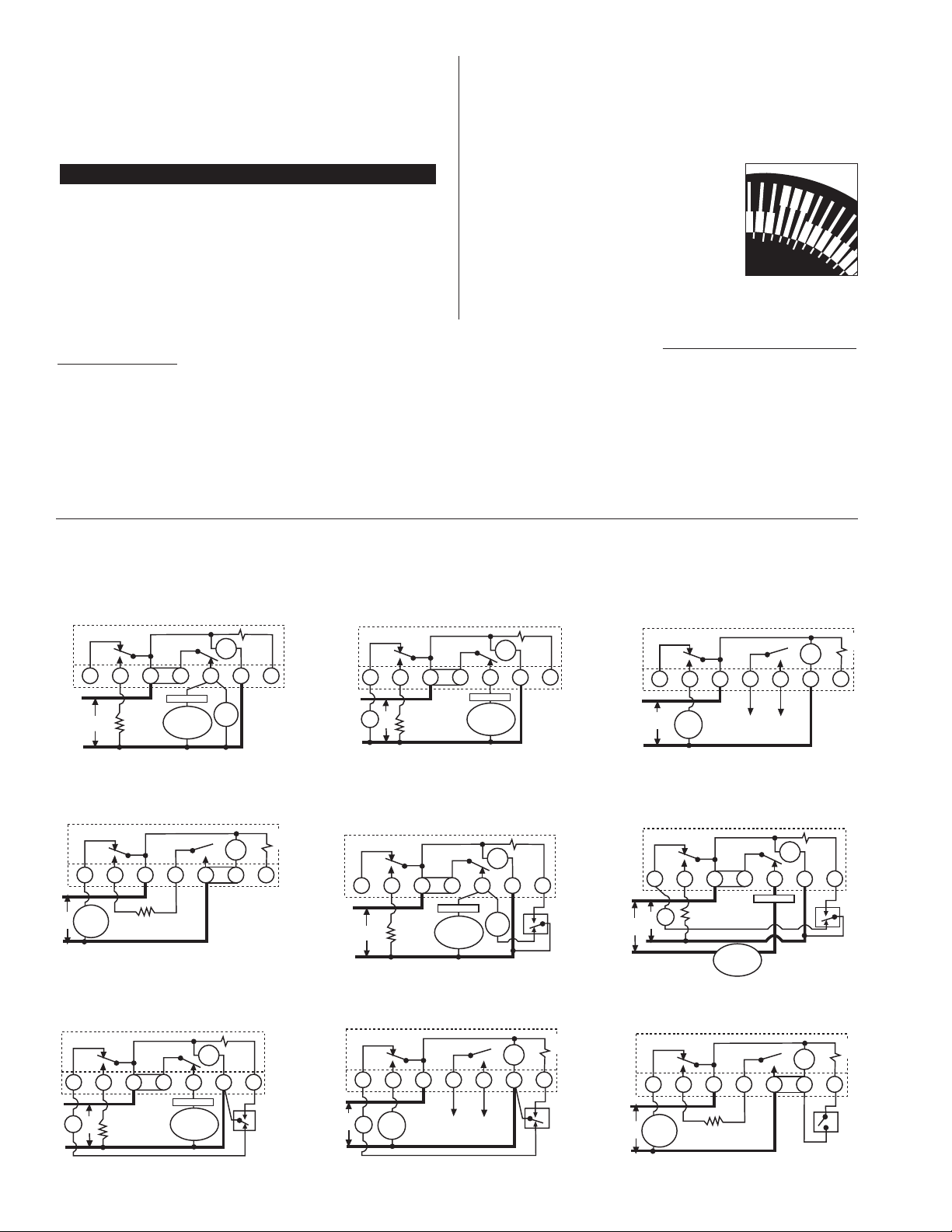
T Y P I C A L W I R I N G DI A G R A MS
All switc h pos itions a re s hown in refrigeration cyc le operation, and change position upon initiation of a defros t.
COM PR E S S OR
OR
SO LE NO ID VA LV E
OR
CON TAC TO R CO IL
FA N
MOT OR
DE FR O ST
HE ATE R
L1
L2
TIME R
TIME R
RE L EA S E
RE L AY
F
3
1-N
2
4 X
LIN E
DT S X T ime/Time - E lec tric Defros t Wiring D iagram
804 5 R eplac ement
S 1 P osition A with 804 5 La bel A pplied
1
THE R MO S TAT
8045
LAB E L
THE R MO S TAT
COM PR E S S OR
OR
SO LE NO ID VA LVE
OR
CON TAC TO R C OIL
DE FR O ST
HE ATE R
L1
L2
TIME R
TIME R
RE L EA S E
RE L AY
1
2
4 X
DT S X T ime/Time - E lec tric Defros t Wiring D iagram
804 1 R eplac ement
S 1 P osition A with 804 1 La bel A pplied
2
8041
LAB E L
3
LIN E
FA N
N
L1
L2
2
4
N
3
DT S X T ime/Time - H ot Ga s D efrost W iring Dia gram
804 3 R eplac ement
S 1 P osition B with 80 43 L abel Applied
3
8043
LAB E L
TIME R
RE L EA S E
RE L AY
TIME R
LIN E
CO NN E C T AC R O S S
CO MP RE S S OR
TH ER MO S TAT
HOT
GA S
VA LV E
F
NO TE : R emove Bridge Betwee n 1-4
1
L1
L2
2
2
DT S X T ime/Time - E lec tric Defros t Wiring D iagram
804 7 R eplac ement - Double P ole Switching
S 1 P osition B with 80 47 L abel Applied
4
8047
LAB E L
TIME R
RE L EA S E
RE L AY
TIME R
NO TE : Move Bridge to 2-2
NO TE :
3
DE FR O ST
HE ATE R
LIN E
SO LE NO ID
VA LV E
OR
CO NTAC TO R
N
4
1
COM PR E S S OR
OR
SO LE NO ID VA LV E
OR
CON TAC TO R CO IL
FA N
MOT OR
DE FR O ST
HE ATE R
L1
L2
TIME R
TIME R
RE L EA S E
RE L AY
TE R MIN ATION
TH ER MO S TAT
W/FA N D EL AY
F
3
1 2
4
X
N
LIN E
DT S X T ime/Temp. - E lectric Defros t Wiring Dia gram
814 5 R eplac ement
S 1 P osition A - N o La bel R equire d
5
THE R MO S TAT
THE R MO S TAT
COM PR E S S OR
OR
SO LE NOI D VA LVE
OR
CON TAC TO R C OIL
DE FR O ST
HE ATE R
L1
N
120V
TIME R
TIME R
RE L EA S E
RE L AY
TE R MIN ATIO N
TH ER MO S TAT
W/FA N D EL AY
1
2
4
X
DT S X T ime/Temp. - E lectric D efrost W iring Dia gram
120 V F an & D efrost H eater; 240 V C ompres sor
S 1 P osition A - N o La bel R equire d
6
3
N
F
FA N
120V
240V
L2
Max. Defros t Heater Load: 120V: 4800Watts
208V: 8320Watts
240V: 9600Watts
8
7
A

N
1
X
N O
C ON N E C T I O N
N
1
3
4
2
2
N O
C ON N E C T I O N
F
3
1
4
2
N
N O
C ON N E C T I O N
F
3
1
2
4
N
X
F
3
1 -N
2
4
X p
p
N
1
3
2
4
X p
p
F
3
1 -N
2
4
X p
p
N
1
3
2
4
X
1
N
3
4
2
X
F
3
1 -N
2
4
X
3
2
4
TE R MINA L IDE NTIF IC ATION
The s tandard DTS X terminal identific ation is identic al to the Pa ragon
8145 with the addition of the "F" terminal. T ermina l identification labels
are provided for the other models to be pla ced over the printed numbers on the printed c irc uit board. From the table below, selec t the
proper labe l, apply to printed c irc uit boa rd, a nd wire per the original
wiring or the wiring diagrams indic ated.
MODE S E LE CT ION (B lue J umperS 1)
The mode selec tor jumper S1 (located at lower
right s ide of the board) de termines the configuration of c ontac ts 2-4. In pos ition "A" the contacts
are normally closed (only when the timer is energized), and will open during a defrost. In position
"B" the 2-4 c ontacts a re normally open, and will
close during a defrost. S elec t proper pos ition
from table below, a nd wiring diagrams indic ated.
To move jumper, pull straight away from board,
and reinsert over the top two pins for position
"B" or the bottom two pins for position "A".
N ote : When S 1 jumper is in "B" pos ition the DTSX will operate as follows. R efrigeration Mode- R E D & G R E E N LED's will turn ON (1&3
and 2&4 bre ak while 1&F make) Defros t Mode- R ED & G RE EN LE D's
will turn O FF (1&3 a nd 2&4 make while 1&F brea k)
8 04 5 R E P L A C E M E N T :
The DTS X with 8045 terminal ID label applied differs from the 8045 in
that terminals 1 and N are combined. This means that the DTSX
model mus t be the same voltage as the defros t c ircuit (defros t he ater,
contactor coil, or hot gas valve). If being us ed in an applic ation where
the defros t c ircuit is 120V and the refrigera tion c ircuit is 240V, the
DTSX must be configured for 120V applic ation (all red jumpe rs ins ert-
ed) with 120V power connec ted to 1 -N and X , a nd the bridge
jumper be tween 1 -N and 2 mus t be removed .
N O T E 1 :8143 R eplacement:
When replac ing a P aragon 8143 or
Precision 6143, wire the termination thermos tat to terminal X of the DTS X and the adja c ent blank terminal. The
Pa ragon and Prec is ion timers are wired to terminal N and the
blank te rmin al . If the termination thermos tat is wired to terminal N
of the DTSX (with the 8143 label attac hed), tempera ture termination
will not oc cur and may res ult in burnout of the DTMV. S ee wiring diagra ms 8 & 9.
8 24 0/6 24 0 S E R I E S R E P L A C E M E N T :
The DTS X may be used to replac e the Pa ragon 8240 or Prec is ion
6240 series defrost timers with integral pres sure termination by the
addition of a remote pressure s witch wired to termina ls X p a nd p of
the DTS X (with an 8240 series terminal label applied). There mus t be
no external voltage connec ted to the pressure s witch. Set pre ssure
switc h cut-in to the s ame value a s s et on the Paragon or P recis ion
defrost timer be ing replac ed. Set c ut-out 6 to 14psi below c ut-in. See
wiring diag rams 10, 11, and 12.
R e c o m m e n de d P r e s s u r e S w i tc hes :Johnson/Penn P170,
Ranc o 010 s eries , or Danfoss K P1 s eries . Pres sure range approximately 35-110ps i, C U T -I N O N P R E S S U R E R I S E .
N O T E 2 :8243 R eplacement:
When replac ing a P aragon 8243 or
Precision 6243, the DTS X white tabs (trippers ) for setting defrost
time and defrost duration must be revers ed. Pull AL L tabs outward.
Press the tabs inward at the des ired defros t initiation times, and for
desire d duration.
COM PR E S S OR
OR
SO LE NOI D VA LV E
OR
CON TAC TOR CO IL
FA N
MOT OR
DE FR O ST
HE ATE R
L1
L2
TIME R
TIME R
RE L EA S E
RE L AY
PR E S S UR E
SW IT CH
F
3
1-N
2
4
LIN E
DT S X Time /Pres sure -E lectric D efrost W iring Dia gram
824 5 R eplac ement
S 1 P osition A with 824 5 La bel A pplied
1 0
THE R MO S TAT
Xp
p
LAB E L
8245
NO TE : R emove B ridge Betwee n 1-N -2
*S ee N ote 2
CO MP RE S S OR
L1
L2
TIME R
TIME R
RE L EA S E
RE L AY
F
3
2
4
LIN E
DT SX T ime/P ress ure-C ompress or S hutdown
824 3 R eplac ement
S 1 P osition B with T rippers R evers ed
1 1
PR E S S UR E
SW IT CH
1-N
p
Xp
LAB E L
8243
DT S X T
L1
L2
4
ime/P res sure-E lec tric De frost W iring Diagra m
824 7 R eplac ement-Double Po le S witching
S 1 P osition B with 82 47 L abel Applied
1 2
8247
LAB E L
TIME R
RE L EA S E
RE L AY
TIME R
NO TE : R emove B ridge Betwee n 3-4
NO TE : Conne ct B ridge B etween 4 -Xp
3
DE FR O ST
HE ATE R
LIN E
SO LE NO ID
VAL V E
OR
CON TAC TO R
N
2
1
p
PR E S S UR E
SW IT CH
Xp
R E P L A C I N G E X I S T I N G D E F R O S T T I M E R S
I MP O R T A N T : When replacing a Gras s lin DT-040 model with a DTS X, the power c onnections must be made to terminals N and 1 on the
DTSX. No c onnection must be made to the X terminal or damage to the unit will result. Disc onnect the power wire from terminal X on the DT-040
and c onnect it to terminal N on the DTSX. Dis c onnect the other power wire from terminal N on the DT-040 and c onnec t it to terminal 1 on the
DTSX. All other wires s hould be connec ted to the DTS X the same as on the DT-040.
The DTSX will replace a ll models of Paragon 8040, 8140, 8240 Series or P recision 6040, 6140, 6240 S eries
1
2
3
4
5 , 6
7
8 , 9
S ee N ote 1
1 0
1 1
S ee N ote 2
1 2
NO TE : In "Terminal La yout," the c onnec ting lines between termina ls indic ate the corre ct positions of the bridges for each model. The heavy line
indic ates the bridg e mus t be ins talled as s hown. T he light line indic ates the bridg e may be removed if different voltage s are us ed at ea ch switc h.
DT S X S 1 P os itio n ÒB Ó
Termin al Typic al
P ara gon P rec is ion G R AS S L IN S 1 Mode Iden t. Wiring Termin al L ay out
Model Mod el Model S ele ctor L abel Diagram (s ee note below)
TIME INIT IATE D, TIME T E RMINATE D
8045 6045 DTSX A None
8046 DTSX A None
8041 6041 DTSX A 8041
8043 6043 DTSX B 8043
8047 6047 DTSX B 8047
TIME INIT IATE D, R E MOT E T EMP E RATUR E OR P R E SS UR E TE R MINA TE D
8145 6145 DTSX A None
8141 6141 DTSX A 8141
8143 6143 DTSX B 8143
TIME INIT IATE D, P RE SS UR E TE R MINA TE D
(S eparate P res sure S witch R equired - s ee instructions )
8245 6245 DTSX A 8245
8243 6243 DTSX B 8243
8247 6247 DTSX B 8247
N O
C ON N E C T I O N

NE W S TYL E
1. Disconnec t power.
2. R emove and s ave ins ulator from Paragon timer.
3. Disconnec t wiring.
4. R emove Paragon mec hanism from enclos ure.
5. R emove Gras slin DT model from it's enc losure.
6. If neces sary, move S1 jumper and apply terminal identification label from plastic bag to DT model as per table
on previous page.
7. L ocate metal clip in plastic bag and as semble it to printed c ircuit board at notch in right side.
8. E ngage tabs on left side of printed circuit board in
enc losure, and swing PC B into plac e until tab on metal
clip engages tang on Pa ragon enclosure.
9. R ec onnect wires , tighten terminal s crews s ecurely.
10. As semble insulator from plas tic bag to Paragon ins ula-
tor by interleaving a s shown.
11. Plac e ins ulator assembly over mec hanism, with notch
and tab over retaining clip, and engaging tab in slot in
tang to retain insulator.
OL D S TYL E and B R AC K ET MOUNT
1. Disconnec t power.
2. R emove and s ave ins ulator from Paragon timer.
3. Disconnec t wiring.
4. R emove and s ave the 6-32 screw. R emove a nd disca rd
two metal pos ts retaining Paragon mechanism.
5. R emove Paragon mec hanism from enclos ure.
6. R emove Gras slin DT model from it's enc losure, and with
pliers, break off the 3 tabs on left side of printed circuit
board.
7. R emove contents of plas tic bag.
8. If neces sary, move S1 jumper and apply terminal identification label to DT model as per table on previous
page.
9. L ocate plastic 3/4"long s tandoff with interna l threads,
and using s crew from Paragon timer, as semble standoff
on t o p of
upper center hole in DT board with s c r ew
throu g h ba c k of board.
10. Plac e board in Para gon enclosure with s ta ndo ff
a li gn e d u nd er hole in the e nc los u r e's uppe r
fla ng e.
11. As semble the 6-32 x 1/4" screw through the tapped
hole in the enclos ure's flange and into the tapped hole
in the standoff. (Hold board and standoff firmly up
against the flange while driving the s crew).
12. As semble the two plastic insulator retainer posts with
screwdriver at two locations where metal posts were
removed.
13. Reconnec t wires , tighten terminal s crews s ecurely.
14. As semble insulator from plas tic bag to Paragon ins ula-
tor by interleaving a s shown.
15. Plac e ins ulator assembly over mec hanism and press
onto pla stic pos ts.
I N S T A L L AT I ON I N E X I S T I NG E N C L OS U R E S
Interleave Grass lin
insulator (top) with
Paragon ins ulator
as s hown here
New Style
Old Style
C A U T I O N : I f the D e f r o s t T i m e r boa r d a s s e m bl y i s not
a s s e m bl e d t o t h e b r a c k e t e x a c tly a s s ho w n a bo v e , a
s hort m ay oc c ur w hic h w il l de s troy t he de fr os t t im e r.
G R A S S L I N C ON T R O L S C OR P O R A T IO N
A GE Indus trial S ys tems C ompany
31 Indus trial Ave. Mahwah, New Jersey 07430
Tel.: 201-825-9696 Fax: 201-825-8694
www.gras slin.com
3/4Ó T hreade d S tandoff
Fr om Ba g Ass embly
6-32 S crew F rom
P aragon B rac ket
Time r Module
Nylon Pos ts
Fr om Ba g
As sembly
Defros t T imer
As sembly
P aragon
Br acke t
Bo ard
 Loading...