

Page 1
DIRECT DRIVE FLUID COOLERS
Technical Guide
Models DFT and BFH
BNFCTB
April 2007
(Replaces 10108.1, 06/02)
Page 2

Table of Contents
Overview . . . . . . . . . . . . . . . . . . . . . . . . . . . . . . . . . . . . . . . . . . . . . . . . . . . . . . . . . . . . . . . . . . . . . . . . . . . . . . . . . . . 3
Direct-Drive Design Features . . . . . . . . . . . . . . . . . . . . . . . . . . . . . . . . . . . . . . . . . . . . . . . . . . . . . . . . . . . . . . . . . . . . . 3
Selection Procedure . . . . . . . . . . . . . . . . . . . . . . . . . . . . . . . . . . . . . . . . . . . . . . . . . . . . . . . . . . . . . . . . . . . . . . . . . . . 4
Selection Formulas . . . . . . . . . . . . . . . . . . . . . . . . . . . . . . . . . . . . . . . . . . . . . . . . . . . . . . . . . . . . . . . . . . . . . . . . . . . . . 4
Solutions . . . . . . . . . . . . . . . . . . . . . . . . . . . . . . . . . . . . . . . . . . . . . . . . . . . . . . . . . . . . . . . . . . . . . . . . . . . . . . . . . . . . 4
Given Conditions . . . . . . . . . . . . . . . . . . . . . . . . . . . . . . . . . . . . . . . . . . . . . . . . . . . . . . . . . . . . . . . . . . . . . . . . . . . . . . 4
Correction Factors . . . . . . . . . . . . . . . . . . . . . . . . . . . . . . . . . . . . . . . . . . . . . . . . . . . . . . . . . . . . . . . . . . . . . . . . . . . . . 5
Model DFT Capacity Ratings . . . . . . . . . . . . . . . . . . . . . . . . . . . . . . . . . . . . . . . . . . . . . . . . . . . . . . . . . . . . . . . . . . . . 6
Model DFT Specications and Dimensions . . . . . . . . . . . . . . . . . . . . . . . . . . . . . . . . . . . . . . . . . . . . . . . . . . . . . . . . . 7
Model BFH Capacity Ratings . . . . . . . . . . . . . . . . . . . . . . . . . . . . . . . . . . . . . . . . . . . . . . . . . . . . . . . . . . . . . . . . . 8-13
Model BFH Dimensions . . . . . . . . . . . . . . . . . . . . . . . . . . . . . . . . . . . . . . . . . . . . . . . . . . . . . . . . . . . . . . . . . . . . . . . 14
Model BFH Specications . . . . . . . . . . . . . . . . . . . . . . . . . . . . . . . . . . . . . . . . . . . . . . . . . . . . . . . . . . . . . . . . . . . . . 15
2
© 2007 Heatcraft Refrigeration Products LLC
Page 3
Overview
Our engineers have carefully selected and matched components to provide excellent performance, long service life
and a wide range of performance selections. Specically engineered for outdoor installations, the DFT and BFH uid
coolers are constructed of aluminum and heavy gauge galvanized steel to resist corrosion in all climates.
Fluid coolers are available in a wide range of sizes. Each model is available with several circuit options to ensure
the exact uid cooler for your requirements. Our uid coolers are designed to reduce the cost of time required for
installation. Each unit is completely assembled and tested at the factory. All motor leads are wired to a junction box
providing a single point for eld wiring.
Direct-Drive Design Features
• Cabinets are heavy-duty construction and designed for outdoor
applications; tube sheets and all structural members are fabricated from
galvanized steel
• Cabinet panels are fabricated from heavy-gauge aluminum for an
attractive appearance and corrosion protection
• Coils are fabricated with corrugated aluminum ns with staggered
copper tubes for optimum heat transfer; all units are pressure-tested,
dehydrated and pressurized prior to shipment
• Alternate coil constructions are available — copper ns, BohnGuard™
ns and coated coils
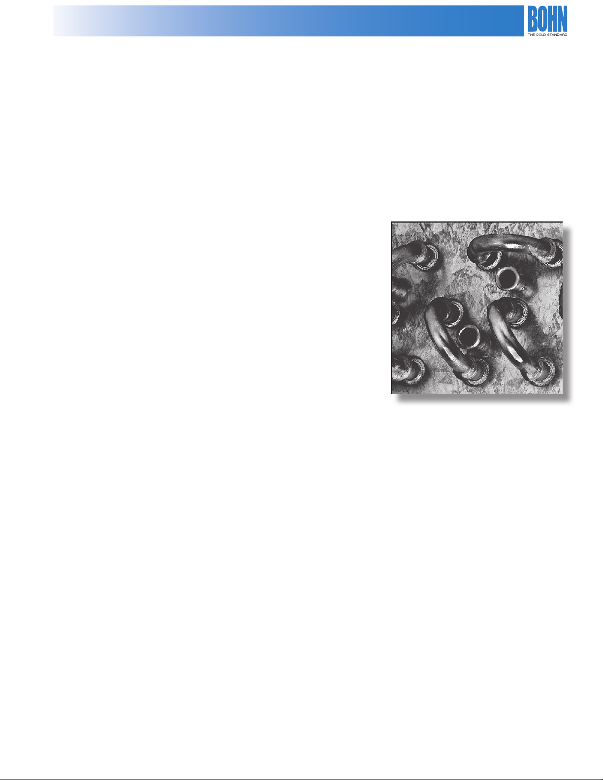
• BFH models incorporate the Floating Tube™ coil design that reduces the
possibility of tube sheet leaks
• DFT models available in either horizontal or vertical air ow; BFH models
available in vertical air ow only
• Fully baed fan sections provide structural strength and prevent fan wind-milling in the o cycle
• Energy ecient fan motors with direct-drive fans available at 1140 RPM; fan motors have thermal overload
protection and permanently lubricated ball bearings
• DFT models are available in 208-230 V single-phase, 208-230/460 dual-voltage, three-phase or 575 V three-phase
motors; BFH models are available in 208-230/460 dual voltage, three-phase or 575 V three-phase motors
• Statically and dynamically balanced fan blades are aluminum and riveted to painted steel spider and hubs
• Fan guards are PVC coated steel for optimum corrosion protection
• All fan motor leads are wired to a weatherproof electrical enclosure for single-point eld wiring
• Fan cycling controls are available that cycle all fans in response to BFH only; DFT fan cycling is ambient air
• All controls are factory mounted and wired; control circuit voltage is 230 V standard, 24 and 115 V controls are
also available
Dramatically Reduces Tube Sheet Leaks
The Floating Tube™ Coil Design
• A wide selection of circuit options maximizes performance at minimal cost
• Sizes available from 10 GPM through 500 GPM
• Units are UL listed for US and Canada
3
Page 4

Selection Procedure
Selection Formulas
Design Capacity = GPM x (Entering Fluid Temperature - Leaving Fluid Temperature) x Fluid Constant, Table 1
Average Fluid Temperature = (Entering Fluid Temperature + Leaving Fluid Temperature)/2
Initial Temperature Dierence, I TD = Entering Fluid Temperature - Entering Air Temperature
Base Capacity = Design Capacity/(1,000 x ITD x Capacity Correction, Table 2 x Altitude Correction Factor, Table 3)
Pressure Drop, Fluid = Pressure Drop, Catalog x Correction Factor, Table 4
Given Conditions
Direct Drive 120˚F Leaving Fluid Temperature
50 GPM 100˚F Entering Air Temperature
20% Ethylene glycol solution 20 feet maximum uid pressure drop
130˚F Entering Fluid Temperature 1,000 feet altitude
Solution
1. Calculate design capacity. From Table 1, select the uid constant for 20% of 484.
Design Capacity = 50 x (130-120) x 484
Design Capacity = 242,000 BTUH
2. Calculate average uid temperature
= (130 +120)/2
= 125˚F
3. Calculate the initial temperature dierence, ITD
ITD = 130 - 100
ITD = 30˚F
4. Calculate Base capacity. From Table 2, for a 20% solution and an average uid temperature of 125˚ F, interpolate
to obtain a correction factor of 1.035. From Table 3, obtain an attitude correction factor at 1000 feet of 0.98.
Base Capacity = 242,000/(1,000 x 30 x 1.035 x 0.98)
Base Capacity = 7.95 MBH / ˚TD
4
Page 5
Correction Factors
5. Select the model and circuiting required. From the capacity tables, locate the GPM you desire and read down
until you nd a base capacity equal to or greater than your calculated base capacity. Read horizontally to the
left to obtain the model and circuiting (Feeds) for your application.
The selection is a DFT 16, with 32 feeds, with a base capacity of 8.34 MBH/1˚ TD and a uid loss of 15.1 feet
of water.
6. Calculate the pressure drop of the uid. From Table 4, using 20% glycol solution and a 125˚F average uid
temperature, interpolate to get a correction factor of 0.86.
Actual Fluid Loss = 15.1 x 0.86
Actual Fluid Loss = 13.0 feet of water
Table 1. Fluid Constraints
Percent
Glycol
Fluid
Constant
0 500
10 493
20 484
30 470
40 453
50 435
Table 3. Altitude Correction Factor
Altitude
(Feet)
Correction
Factor
0 1.00
1,000 0.98
2,000 0.95
3,000 0.93
4,000 0.90
5,000 0.88
6,000 0.85
7,000 0.83
Table 2. Capacity Correction Factor
Percent
Glycol
0 0.97 1.01 1.03 1.05 1.07
10 0.96 1.00 1.02 1.04 1.06
20 0.94 0.98 1.00 1.02 1.04
30 0.92 0.96 0.98 1.00 1.02
40 0.90 0.94 0.96 0.98 1.00
50 0.87 0.91 0.94 0.96 0.98
Note: For average uid temperature less than 50˚F or greater than 130˚F, consult
the factory
Average Fluid Temperature ˚F
50 70 90 110 130
Table 4. Correction Factor for Fluid Loss
Percent
Average Fluid Temperature ˚F
Ethylene
Glycol
50 70 90 110 130
0 0.88 0.82 0.78 0.75 0.71
10 0.97 0.90 0.86 0.82 0.78
20 1.05 0.98 0.94 0.89 0.85
30 1.15 1.07 1.02 0.98 0.93
40 1.24 1.15 1.10 1.05 1.00
50 1.33 1.23 1.18 1.12 1.07
5
Page 6

Capacity Ratings
Table 5. Capacity Ratings MBH / oTD, 40% Ethylene Glycol at 130oF Average Fluid Temperature
GPM
Model Feeds
DFT
005
8
12
16
12
DFT
Model DFT
008
16
21
32
DFT
010
DFT
012
DFT
014
DFT
016
DFT
021
DFT
023
DFT
026
* PD is glycol uid loss in feet of water at 130˚F uid temperature
12
16
24
12
16
24
12
16
24
12
21
32
16
24
48
24
48
21
32
64
10 15 20 25 30 40 50 60
MBH PD* MBH PD* MBH PD* MBH PD* MBH PD* MBH PD* MBH PD* MBH PD*
2.36
14.0
2.71
28.7
2.23
3.07 7.4 3.67
3.46 7.5 4.32
3.62 7.5 4.62
3.92 9.4 5.12
4.7
2.58
2.47
3.55
4.16
4.45
4.96
9.7
2.80
4.5
2.70
15.1
4.04
7.0
3.92
3.79
15.5
4.88
7.1
4.73
4.46
15.5
5.30
7.1
5.12
4.81
19.3
8.9 5.78
5.49
16.1
7.5
25.2
11.6
5.6
25.7
11.9
4.0
25.7
11.9
4.0
14.7
5.0
2.95
24.0
2.85
11.2 2.97 15.5
4.17
17.3
4.05
5.13
4.86
5.61
5.30
6.39
6.08
8.4
17.6
6.0
17.6
6.0
21.9
7.4 6.53 10.2 7.19 16.9 7.64 25.2
4.35
4.24
4.02
5.42
5.17
5.99
5.68
23.8
11.5
3.8
4.49
4.30
19.2
6.4
24.3
8.3 5.60 13.8 5.89 20.4 6.10 28.2
24.3
8.3 6.23 13.8 6.60 20.4 6.88 28.2
4.17 12.4 5.57 25.4
7.27 9.2 8.44
5.93 12.3 7.22
6.93
6.99 6.8 7.98 10.2 8.78 14.0 9.96
7.65 12.9 8.81
20.5
6.8 7.90 10.2 8.68 14.0 9.83
6.57
8.44
13.7
4.4
19.1
6.1
9.43
7.09
9.73
9.33
18.9
6.1 7.84 10.2 8.34 15.1 8.70 20.9
23.3
8.97
3.7 9.78 5.5 10.41 7.5
23.3
9.25
3.7 10.14 5.5 10.82 7.5
26.3
8.4 10.66 14.0 11.58
4.66
4.49
10.63
28.5
9.4 4.62 13.0
20.8
3.3
12.25
11.33
28.7
4.5
Table 6. Capacity Ratings MBH / ˚TD, 40% Ethylene Glycol at 130˚F Average Fluid Temperature
GPM
Model Feeds
DFT
48 10.89 9.9 11.29 12.6 11.61 15.5 11.88 18.6 12.12 22.1 12.31 25.7
021
DFT
48 11.36 9.9 11.80 12.6 12.16 15.5 12.46 18.6 12.72 22.1 12.94 25.7
023
DFT
64 11.88 6.0 12.33 7.5 12.69 9.3 12.98 11.2 13.24 13.3 13.46 15.5 13.64 17.8 13.81 20.3 13.95 23.0 14.08 25.7
026
* PD is glycol uid loss in feet of water at 130˚F uid temperature
70 80 90 100 110 120 130 140 150 160
MBH PD* MBH PD* MBH PD* MBH PD* MBH PD* MBH PD* MBH PD* MBH PD* MBH PD* MBH PD*
Table 7. Model DFT Connection Sizes, based on the number of feeds
Feeds Inlet/Outlet
8 1-1/8” ODS
12 1-3/8” ODS
16 1-3/8” ODS
21 1-5/8” ODS
Feeds Inlet/Outlet
24 2-1/8” ODS
32 2-1/8” ODS
48 2-5/8” ODS
64 2-5/8” ODS
6
Page 7

Specications and Dimensions
Diagram 1. Model DFT Dimensions, 5 through 26 Tons with Vertical Air Flow
Diagram 2. Model DFT Dimensions, 5 through 26 Tons with Horizontal Air Flow
Model DFT
Table 8. Model DFT Specications
Dimensions
Model
DFT005
DFT008
DFT010
DFT012
DFT014
DFT016
DFT021
DFT023
DFT026
1
Motor voltage 208-230/1/60; 1075 RPM
2
Motor voltage 208-230-460/3/60; 1140 RPM
(in.)
A B No. Dia. HP1FLA1HP
39-3/4
49-3/4
69-3/4
69-3/4
89-3/4
89-3/4
129-3/4
129-3/4
129-3/4
120
120
120
30
40
60
60
80
80
CFM
5,050
6,450
10,100
12,400
13,700
12,900
20,500
19,900
19,400
Fan Motor Data
1
24
1/3
1
26
1/2
2
24
1/3
2
26
1/2
2
26
1/2
2
26
1/2
3
26
1/2
3
26
1/2
3
26
1/2
3.4
3.9
6.8
7.8
7.8
7.8
11.7
11.7
11.7
1/3
1/3
1/3
1/3
1/3
1/3
1/3
1/3
1/3
Approx.
Net Wt.
2
FLA
2.6/1.3
2.6/1.3
5.2/2.6
5.2/2.6
5.2/2.6
5.2/2.6
7.8/3.9
7.8/3.9
7.8/3.9
2
(Lbs.)
205
260
330
348
420
436
565
580
610
7
Page 8

Capacity Ratings
Table 9. Capacity Ratings MBH / ˚TD, 40% Ethylene Glycol at 130˚F Average Fluid Temperature
Model Feeds
BFH
0231428
BFH
027
BFH
031
BFH
035
BFH
041
BFH
Model BFH
045
BFH
046
BFH
049
* PD is glycol uid loss in feet of water at 130˚F uid temperature
Fan
Cong.
1 x 2
14
21421 x 2
14
21421 x 2
18
28561 x 2
14
21421 x 3
14
21421 x 3
18
28562 x 2
18
28561 x 3
20 30 40 50 60 70 80 90 100
MBH PD* MBH PD* MBH PD* MBH PD* MBH PD* MBH PD* MBH PD* MBH PD* MBH PD*
6.4 3.2 8.04 6.5 9.18
8.08
7.01 4.8 8.85
7.42 4.8 9.56
8.19 7.0 10.99
9.9
10.1
8.39
3.2
9.60
9.9
11.04
9.02
3.2
10.45
10.2 6.6 11.88
11.2
14.3
13.04
10.54
4.6
12.52
11.62
14.3
14.03
11.15
4.6
13.43
11.24 6.6 13.63
12.8
11.92 9.5 14.49
13.85
10.8
10.01
16.1
10.64
1.5
8.9
2.3
9.55
16.5
10.99
24.4
5.3
10.49
16.5
5.3
11.51
11.0
13.08
3.2
12.38
23.8
7.7 14.02 11.4 15.19
23.8
7.7 15.21 11.4 16.61
11.0
15.54
3.2
15.9
16.45
4.6
15.73
7.9 11.17
10.06
12.1
24.4
7.9 12.32
10.99
16.3
13.98
4.7
13.29
13.83
14.99
16.3
17.08
14.6
4.7
16.08
23.5
6.9 17.22 9.5 18.41 12.4 19.37
GPM
22.2
3.1 10.07 4.1 10.51 5.2 10.87 6.4 11.18 7.8
10.8
11.7
14.2
12.13
18.0
12.48
22.2
1.5
10.62
2.0
10.8
1.5
22.5
6.5
15.8
2.3
15.8
2.3
22.5
6.5
12.95
11.64
14.66
13.99
16.13
14.76
17.74
16.09
18.35
17.31
11.08
14.2
13.47
2.0
12.19
29.5
8.6 14.55
13.16
20.7
16.90
3.0
15.54
20.7
18.66
3.0
17.01
29.5
8.6 18.35
16.17
17.69
2.6
11.47
3.1 11.8 3.8
18.0
13.89
22.2
2.6
12.65
3.1 13.05 3.8
10.8
15.01
13.4
15.39
1.5
13.67
1.9
14.1
26.2
3.7 16.19 4.6 16.76 5.6
26.2
3.7 17.79 4.6 18.46 5.6
10.8
19.24
13.4
20.01
1.5
17.04
1.9
17.81
15.8
20.18
19.4
20.85
2.3
18.51
2.8
19.22
16.1
2.3
16.1
2.3
23.4
3.3
8
Page 9

Capacity Ratings
Table 10. Capacity Ratings MBH / ˚TD, 40% Ethylene Glycol at 130˚F Average Fluid Temperature
Model Feeds
BFH
0542842
BFH
053
BFH
0602842
BFH
0612142
BFH
0663656
BFH
065
BFH
0703656
BFH
071
BFH
0752142
BFH
079
BFH
0802842
BFH
0862842
BFH
0902842
BFH
089
BFH
0972856
BFH
0983656
BFH
1072856
* PD is glycol uid loss in feet of water at 130˚F uid temperature
Fan
Cong.
2 x 2
14
21421 x 4
2 x 2
1 x 4
2 x 2
18
28561 x 4
2 x 2
18
28561 x 4
1 x 5
18
28561 x 5
2 x 3
2 x 3
2 x 3
18
28561 x 5
1 x 6
2 x 3
1 x 6
20 30 40 50 60 70 80 90 100
MBH PD* MBH PD* MBH PD* MBH PD* MBH PD* MBH PD* MBH PD* MBH PD* MBH PD*
14.03 4.8 16.06 7.2 17.70
8.71 9.2 12.20
18.4
11.86
6.1 14.50 10.1 16.62 15.0 18.32
14.84 4.8 17.18 7.2 19.12
12.34 6.1 15.34 10.1 17.80 15.0 19.81
12.88 12.5 16.23
13.04 12.5 16.53
12.97 7.5 16.52 12.5 19.56 18.5 22.14
13.20 15.4 16.90
13.40 15.4 17.39
20.7
15.71
6.1 18.31 9.0 20.44 12.4 22.21 16.3 23.68
20.7
16.01
6.1 18.76 9.0 21.04 12.4 22.93 16.3 24.50
25.6
16.51
7.5 19.53 11.1 22.08 15.4 24.23 20.2 26.06
16.38 7.0 19.38 10.4 21.97
16.69 7.0 19.89 10.4 22.67
16.93 7.0 20.29 10.4 23.23
2.56
17.03
7.5 20.38 11.1 23.27 15.4 25.75 20.2 27.87
17.22 8.9 20.70 13.3 23.74 18.3 26.38 24.1
17.59 8.9 21.37 13.3 24.76 18.3 27.76 24.1
GPM
9.9
19.06
13.0
20.19
16.78
3.2
18.10
4.2
19.21
20.7
19.71
27.1
16.85
3.0
18.18
3.9 19.30 4.9 20.27 6.1 21.10 7.3
9.9
20.73
13.0
22.09
18.05
3.2
19.60
4.2
20.92
20.7
21.47
27.2
18.12
3.0
19.68
3.9 21.01 4.9 22.15 6.1 23.14 7.4
17.77 4.8 19.84 6.6 21.55 8.7 22.99
21.71
21.80
18.21 4.8 20.41 6.6 22.24 8.7 23.78
22.41
22.50
25.6
20.53
3.7 22.54 4.9 24.28 6.1 25.80 7.6 27.13 9.1
24.27
14.3
24.18
18.8
26.08
21.09
4.6
23.21
6.1
25.04
14.3
25.07
18.8
27.16
21.76
4.6
24.04
6.1
26.03
14.3
25.81
18.8
28.05
22.30
4.6
24.73
6.1
26.86
25.84
26.92 4.4 28.78 5.4 30.43 6.5
20.73 6.9 23.84 9.5 26.58 12.5 28.97
27.70
28.48 4.4 30.61 5.4 32.50 6.5
16.5
21.15
20.3
21.97
24.4
5.3
20.16
16.5
23.24
5.3
22.05
11.0
24.21
3.2
22.90
20.7
24.91
3.0
23.00
11.0
25.08
3.2
23.68
20.7
25.82
3.0
23.78
25.6
3.7 25.76 4.5 27.06 5.5
23.8
27.73
7.7
26.64
23.8
28.97
7.7
27.78
23.8
30.01
7.7
28.74
25.6
3.7 27.55 4.5 29.04 5.5
15.9
31.07
4.6
29.70
6.5
20.99
20.3
24.22
24.4
6.5
23.03
13.5
25.25
16.3
3.9
23.94
25.5
3.7 24.04 4.4
13.5
26.19
16.3
3.9
24.78
25.5
3.7 24.88 4.4
29.4
9.5 28.05 11.4
29.4
9.5 29.32 11.4
29.4
9.5 30.41 11.4
19.5
32.91
23.5
5.7
31.46
7.9
7.9
Model BFH
4.7
4.7
6.9
9
Page 10

Capacity Ratings
Table 11. Capacity Ratings MBH / ˚TD, 40% Ethylene Glycol at 130˚F Average Fluid Temperature
Fan
Model Feeds
BFH
1062842
BFH
1202842
BFH
1323656
BFH
1403656
BFH
152
BFH
1623656
BFH
1683656
Model BFH
BFH
178
BFH
194
BFH
202
BFH
212
* PD is glycol uid loss in feet of water at 130˚F uid temperature
42
56
56
56
56
Con-
g.
2 x 4
2 x 4
2 x 4
2 x 4
2 x 5
2 x 5
2 x 5
2 x 5
2 x 6
2 x 6
2 x 6
20 30 40 50 60 70 80 90 100
MBH PD* MBH PD* MBH PD* MBH PD* MBH PD* MBH PD* MBH PD* MBH PD* MBH PD*
17.42 9.2 21.10 13.6 24.41
17.74 9.2 21.70 13.6 25.35
GPM
18.7
27.35
24.6
23.71
6.1
26.51
8.0 29.01 10.1 31.24 12.4 33.23 15.0
18.7
28.68
24.6
24.67
6.1
27.83
8.0 30.68 10.1 33.26 12.4 35.60 15.0
21.96 9.0 25.77 12.5 29.27 16.4 32.45
31.41
22.13 9.0 26.06 12.5 29.71 16.4 33.07
32.02
25.94 7.5 29.62 9.9 33.03 12.5 36.20 15.4 39.11 18.5
22.33 11.2 26.41 15.4 30.24 20.2 33.81
33.03
22.45 11.2 26.64 15.4 30.62 20.2 34.62
33.61
34.06 7.5 37.53 9.2 40.76 11.1
34.44 8.9 38.03 11.0 41.39 13.3
34.86 8.9 38.61 11.0 42.15 13.3
35.17 8.9 39.05 11.0 42.74 13.3
20.7
35.34
25.6
37.94
30.8
6.1
34.14
7.5
36.61
9.0
20.7
36.12
25.6
6.1
34.90
7.5 37.52 9.0
25.6
7.5 36.17 9.2 39.06 11.1
25.6
7.5 36.92 9.2 40.00 11.1
10
Page 11

Capacity Ratings
Table 12. Capacity Ratings MBH / ˚TD, 40% Ethylene Glycol at 130˚F Average Fluid Temperature
Model Feeds
Fan
Cong.
120 140 160 180 200 220 240 260 280
MBH PD* MBH PD* MBH PD* MBH PD* MBH PD* MBH PD* MBH PD* MBH PD* MBH PD*
GPM
BFH023
BFH027
BFH
BFH
BFH
BFH
BFH
BFH
BFH
BFH
BFH
BFH
BFH
BFH
BFH
BFH
28 1 x 2 11.69 10.7
42 1 x 2 12.33 5.2 12.74 6.9 13.07 8.7 13.34 10.7
031 42 1 x 2 13.68 5.2 14.17 6.9 14.57 8.7 14.89 10.7
28
035
56
041 42 1 x 3 17.67 7.7 18.39 10.1 18.96 12.8 19.40 15.7
045 42 1 x 3 19.56 7.7 20.42 10.1 21.10 12.8 21.66 15.7
049 56 1 x 3 20.36 4.6 21.24 6.1 21.95 7.7 22.52 9.5 22.99 11.4 23.39 13.5 23.74 15.7
28
046
56
42
054
84
053 42 1 x 4 22.45 10.1 23.53 13.3 24.39 16.9 25.09 20.8
42
060
84
061 42 1 x 4 24.77 10.1 26.05 13.3 27.08 16.9 27.93 20.8
0663656
112
065 56 1 x 4 25.75 6.1 27.08 8.0 28.15 10.1 29.02 12.5 29.75 15.0 30.36 17.8 30.89 20.8
0703656
112
071 56 1 x 4 26.70 6.1 28.12 8.0 29.25 10.1 30.17 12.5 30.94 15.0 31.58 17.8 32.13 20.8
1 x 2
2 x 2
2 x 2
2 x 2
2 x 2
2 x 2
15.98
22.2
14.79
3.1 15.32 4.1 15.74 5.2 16.07 6.4 16.35 7.8 16.59 9.2 16.79 10.7
21.27
22.2
19.10
3.1 20.15 4.1 21.01 5.2 21.74 6.4 22.37 7.8 22.91 9.2 23.38 10.7
22.34
10.8
23.40
14.2
24.26
18.0
24.96
20.12
24.65
21.98
26.92
25.63
27.98
26.59
1.5
10.8
1.5
22.5
6.5
22.5
6.5
21.24
25.93
23.30
28.21
26.96
29.34
28.00
2.0
22.16
14.2
26.95
2.0
24.40
29.5
8.6 28.03
25.43
29.5
8.6 29.13
26.34
2.6
18.0
2.6
10.8
1.5
10.8
1.5
22.2
22.93
3.1 23.59 3.8 24.16 4.5 24.66 5.2 25.10 6.0 25.49 6.9
27.80
22.2
25.32
3.1 26.11 3.8 26.79 4.5 27.39 5.2 27.91 6.0 28.37 6.9
28.90
13.4
29.62
16.1
26.38
30.05
27.36
1.9
13.4
1.9
27.20
30.81
28.22
2.3
16.1
2.3
30.23
27.90
31.45
28.96
19.1
2.7
19.1
2.7
30.75
28.51
32.00
29.60
Model BFH
22.2
3.1 29.04 3.6 29.51 4.1
22.2
3.1 30.17 3.6 30.67 4.1
* PD is glycol uid loss in feet of water at 130˚F uid temperature
* PD is glycol uid loss in feet of water at 130˚F uid temperature
11
Page 12

Capacity Ratings
Table 13. Capacity Ratings MBH / ˚TD, 40% Ethylene Glycol at 130˚F Average Fluid Temperature
42
56
56
56
56
Fan
Cong.
1 x 5
1 x 5
2 x 3
2 x 3
1 x 5
2 x 3
1 x 6
2 x 3
1 x 6
2 x 4
2 x 4
2 x 4
2 x 4
2 x 5
2 x 5
2 x 5
2 x 5
2 x 6
2 x 6
2 x 6
120 140 160 180 200 220 240 260 280
MBH PD* MBH PD* MBH PD* MBH PD* MBH PD* MBH PD* MBH PD* MBH PD* MBH PD*
29.34 12.6 31.09 16.5 32.52 20.9 33.69 25.8
29.21 7.6 30.92 9.9 32.30 12.6 33.44 15.5 34.39 18.7 35.20 22.1 35.89 25.8
30.40
15.8
32.27
20.7
27.66
2.3
29.52
3.0
31.91
15.8
33.98
20.7
28.91
2.3
30.94
3.0
31.52 7.6 33.49 9.9 35.06 12.6 36.36 15.5 37.43 18.7 38.34 22.1 39.12 25.8
33.21
15.8
35.47
20.7
29.98
2.3
32.17
3.0
33.19 9.0 35.40 11.9 37.20 15.0 38.69 18.5 39.95 22.3 41.02 26.4
34.43 9.5 36.81 12.4 38.75
35.68 9.0 38.23 11.9 40.31 15.0 42.02 18.5 43.45 22.3 44.66 26.4
36.64
20.7
39.42
27.1
33.71
3.0
36.37
3.9 38.62 4.9 40.54 6.1 42.20 7.3 43.64 8.7 44.92 10.1 46.05 11.7 47.06 13.3
39.62
20.7
42.95
27.1
36.24
3.0
39.36
3.9 42.02 4.9 44.30 6.1 46.28 7.3 48.01 8.7 49.54 10.1 50.89 11.7 52.10 13.3
40.89 12.4 44.42 16.3 47.35
42.08 12.4 45.85 16.3 49.00
44.27
25.6
41.05
3.7 45.08 4.9 48.56 6.1 51.59 7.6 54.25 9.1 56.59 10.8 58.66 12.6 60.51 14.5 62.17 16.5
44.16 15.4 48.47 20.2 52.13
45.46 15.4 50.11 20.2 54.07
46.55 15.4 51.50 20.2 55.74
47.47 18.3 52.75 24.1
48.61 18.3 54.26 24.1
49.52 18.3 55.52 24.1
Model Feeds
BFH
075
BFH
079
BFH
0804284
BFH
0864284
BFH
089
BFH
0904284
BFH
097
BFH
09856112
BFH
Model BFH
107
BFH
1064284
BFH
1204284
BFH
13256112
BFH
14056112
BFH
1524284
BFH
16256112
BFH
16856112
BFH
17856112
BFH
19456112
BFH
20256112
BFH
21256112
* PD is glycol uid loss in feet of water at 130˚F uid temperature
GPM
33.81
26.2
31.08
3.7 32.39 4.6 33.52 5.6 34.50 6.6 35.36 7.7 36.12 8.8 36.79 10.1
35.67
26.2
32.65
3.7 34.09 4.6 35.34 5.6 36.42 6.6 37.36 7.7 38.19 8.8 38.94 10.1
37.31
26.2
34.02
3.7 35.58 4.6 36.93 5.6 38.10 6.6 39.12 7.7 40.03 8.8 40.83 10.1
15.8
40.35
19.4
41.70
23.4
42.84
27.7
35.39
2.3
37.03
2.8
38.43
20.7
49.82
25.5
43.59
3.0
46.00
3.7 48.08 4.4 49.90 5.2 51.50 6.1 52.91 7.0 54.16 8.0
20.7
51.64
25.5
44.99
3.0
47.55
3.7 49.77 4.4 51.70 5.2 53.40 6.1 54.90 7.0 56.24 8.0
25.6
48.54
3.7 51.52 4.5 54.13 5.5 56.42 6.5 58.44 7.6 60.25 8.7 61.86 9.9
25.6
50.23
3.7 53.44 4.5 56.25 5.5 58.72 6.5 60.91 7.6 62.85 8.7 64.59 9.9
25.6
51.69
3.7 55.11 4.5 58.10 5.5 60.74 6.5 63.07 7.6 65.14 8.7 66.99 9.9
53.83 4.4 57.57 5.4 60.86 6.5 63.78 7.8 66.37 9.0 68.70 10.4 70.79 11.9
55.52 4.4 59.53 5.4 63.08 6.5 66.23 7.8 69.04 9.0 71.56 10.4 73.82 11.9
56.95 4.4 61.21 5.4 64.99 6.5 68.36 7.8 71.36 9.0 74.04 10.4 76.46 11.9
3.3
39.65
4.0 40.72 4.6 41.65 5.3 42.48 6.1
12
Page 13

Capacity Ratings
Table 14. Capacity Ratings MBH / ˚TD, 40% Ethylene Glycol at 130˚F Average Fluid Temperature
Model Feeds
Fan
Cong.
300 350 400 450 500
MBH PD* MBH PD* MBH PD* MBH PD* MBH PD*
BFH054 84 2 x 2 25.83 7.8 26.56 10.2
BFH060 84 2 x 2 28.78 7.8 29.65 10.2
BFH066 112 2 x 2 29.94 4.7 30.82 6.1 31.50 7.8 32.06 9.6 32.53 11.5
BFH070 112 2 x 2 31.11 4.7 32.03 6.1 32.75 7.8 33.33 9.6 33.80 11.5
BFH080 84 2 x 3 37.40 11.4 38.66 15.0
BFH086 84 2 x 3 39.60 11.4 40.99 15.0
BFH090 84 2 x 3 41.55 11.4 43.06 15.0
BFH098 112 2 x 3 43.22 6.9 44.77 9.0 45.98 11.4 46.97 14.0 47.77 16.9
BFH106 84 2 x 4 47.96 15.0 49.87 19.8
BFH120 84 2 x 4 53.18 15.0 55.46 19.8
BFH132 112 2 x 4 55.29 9.0 57.63 11.9 59.50 15.0 61.00 18.5 62.24 22.3
BFH140 112 2 x 4 57.43 9.0 59.92 11.9 61.87 15.0 63.45 18.5 64.74 22.3
BFH152 84 2 x 5 63.67 18.7 66.82 24.5
BFH162 112 2 x 5 63.30 11.2 66.36 14.8 68.80 18.7 70.78 23.0 72.42 27.7
BFH168 112 2 x 5 66.15 11.2 69.43 14.8 72.04 18.7 74.16 23.0 75.91 27.7
BFH178 112 2 x 5 68.65 11.2 72.14 14.8 74.90 18.7 77.12 23.0 78.96 27.7
BFH194 112 2 x 6 72.69 13.4 76.69 17.6 79.90 22.3 82.52 27.5 84.70 33.1
BFH202 112 2 x 6 75.87 13.4 80.18 17.6 83.63 22.3 86.45 27.5 88.78 33.1
BFH212 112 2 x 6 78.64 13.4 83.24 17.6 86.90 22.3 89.87 27.5 92.33 33.1
* PD is glycol uid loss in feet of water at 130˚F uid temperature
GPM
Model BFH
Table 15. Model BFH Connection Sizes, based on number of feeds
Single Row of Fans
Feeds Inlet/Outlet
14 2-1/8” ODS
18 2-1/8” ODS
21 2-5/8” ODS
28 2-5/8” ODS
42 3-1/8” ODS
56 3-5/8” ODS
Double Row of Fans
Feeds Inlet/Outlet
18 2 @ 2-1/8” ODS
28 2 @ 2-1/8” ODS
36 2 @ 2-1/8” ODS
42 2 @ 2-5/8” ODS
56 2 @ 2-5/8” ODS
84 2 @ 3-1/8” ODS
112 2 @ 3-5/8” ODS
13
Page 14

Dimensions
127”
20.25”
106”
112”
180”
20.25”
53” 53” 53”
165”
233”
20.25”
106”
218”
106”
286”
20.25”
53” 53” 53” 53” 53”
271”
339”
20.25”
53” 53” 53” 53” 53” 53”
324”
3,223 mm
515 mm
2,692 mm
2,845 mm
515 mm
4,572 mm
1,346 mm 1,346 mm1,346 mm
4,191 mm
1,346 mm 1,346 mm
1,346 mm
1,346 mm
1,346 mm
515 mm
515 mm
1,346 mm 1,346 mm
1,346 mm
1,346 mm
1,346 mm
1,346 mm
515 mm
2,692 mm
2,692 mm
5,918 mm
5,537 mm
7,264 mm
6,883 mm
8,611 mm
8,230 mm
45.43”
42.43”
38.00”
49.13”
88”
85”
49.13”
80.50”
1,154 mm
1,008 mm
965 mm
1,248 mm
2,355 mm
2,159 mm
0.875” [22 mm]
diameter mtg.
0.875” [22 mm]
diameter mtg.
holes typ.
2,045 mm
1,248 mm
Diagram 3. Model BFH Dimensions
End Views
Single
Row
Model BFH
Double
Row
Side Views
1 x 2
2 x 2
1 x 3
2 x 3
1 x 4
2 x 4
14
1 x 5
2 x 5
1 x 6
2 x 6
Page 15

Specications
Table 16. Model BFH Specications
Model
BFH023
BFH027
BFH031
BFH035
BFH041
BFH045
BFH049
BFH053
BFH061
BFH065
BFH071
BFH075
BFH079
BFH089
BFH097
BFH107
BFH046
BFH054
BFH060
BFH066
BFH070
BFH080
BFH086
BFH090
BFH098
BFH106
BFH120
BFH132
BFH140
BFH152
BFH162
BFH168
BFH178
BFH194
BFH202
BFH212
Fan Data
Fan
Cong.
1 x 2
1 x 2
1 x 2
1 x 2
1 x 3
1 x 3
1 x 3
1 x 4
1 x 4
1 x 4
1 x 4
1 x 5
1 x 5
1 x 5
1 x 6
1 x 6
2 x 2
2 x 2
2 x 2
2 x 2
2 x 2
2 x 3
2 x 3
2 x 3
2 x 3
2 x 4
2 x 4
2 x 4
2 x 4
2 x 5
2 x 5
2 x 5
2 x 5
2 x 6
2 x 6
2 x 6
1
No. of
Fans
2
2
2
2
3
3
3
4
4
4
4
5
5
5
6
6
4
4
4
4
4
6
6
6
6
8
8
8
8
10
10
10
10
12
12
12
CFM
208-230/3/60 575/3/60 460/3/60
Single Row of Fans
19,780
19,800
19,110
18,340
29,700
28,660
28,070
38,600
37,250
38,020
35,710
46,610
46,200
44,580
55,400
53,460
Double Row of Fans
39,570
39,600
38,210
37,530
36,770
59,400
58,510
57,320
56,240
77,200
74,500
72,790
71,310
93,120
92,400
91,010
89,170
110,900
109,240
107,020
14.0
14.0
14.0
14.0
21.0
21.0
21.0
28.0
28.0
28.0
28.0
35.0
35.0
35.0
42.0
42.0
28.0
28.0
28.0
28.0
28.0
42.0
42.0
42.0
42.0
56.0
56.0
56.0
56.0
70.0
70.0
70.0
70.0
84.0
84.0
84.0
FLA
2
5.6
5.6
5.6
5.6
8.4
8.4
8.4
11.2
11.2
11.2
11.2
14.0
14.0
14.0
16.8
16.8
11.2
11.2
11.2
11.2
11.2
16.8
16.8
16.8
16.8
22.4
22.4
22.4
22.4
28.0
28.0
28.0
28.0
33.6
33.6
33.6
7.0
7.0
7.0
7.0
10.5
10.5
10.5
14.0
14.0
14.0
14.0
17.5
17.5
17.5
21.0
21.0
14.0
14.0
14.0
14.0
14.0
21.0
21.0
21.0
21.0
28.0
28.0
28.0
28.0
35.0
35.0
35.0
35.0
42.0
42.0
42.0
Operating
Charge
(Gal.)
6.6
9.0
9.0
11.6
12.8
12.8
16.4
16.4
16.4
21.3
21.3
20.0
26.1
26.1
31.0
31.0
13.3
18.2
18.2
23.1
23.1
25.4
25.4
25.4
32.8
32.7
32.7
42.5
42.5
40.0
52.1
52.1
52.1
62.0
62.0
62.0
Approx.
Net Wt.
†
(lbs.)
720
760
780
860
1,170
1,190
1,220
1,550
1,590
1,620
1,730
1,960
1,960
2,200
2,350
2,580
1,560
1,600
1,650
1,670
1,780
2,350
2,400
2,500
2,560
3,080
3,140
3,190
3,450
3,920
3,930
4,070
4,300
4,620
4,800
5,130
Model BFH
Notes:
1
All fan blades are 30" diameter
2
All motors are 1-1/2 HP, 208-230/460/3/60, 1140 RPM
†
Does not include operating charge
15
Page 16

For more information on Bohn refrigeration products, contact
your sales representative or visit us at www.thecoldstandard.com.
A Brand of Heatcraft Refrigeration Products LLC
2175 West Park Place Blvd. • Stone Mountain, GA 30087
800.537.7775 • FAX 770.465.5990
www.thecoldstandard.com
Since product improvement is a continuing eort, we reserve the right to
make changes in specications without notice.
BN-FCTB-0407 | version 000
 Loading...