

Page 1
AIR-COOLED CONDENSERS
Technical Guide
BN-ACCTB
November 2015
Replaces BN-ACCTB, May 2014
Page 2
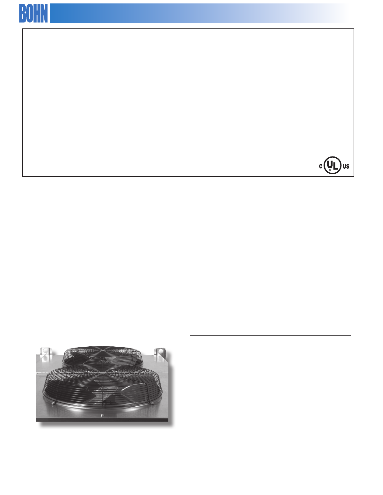
TABLE OF CONTENTS
Overview.................................................................................. 2, 3
Features & Options............................................................... 3, 4
Three Solutions............................................................................5
Nomenclature..............................................................................6
Condenser Selection Procedure........................................7-9
Fixed Speed A/C Series
540 RPM .............................................................................10-12
830 RPM (1.0 HP)..............................................................13-15
830 RPM (1.5 HP)..............................................................16-18
1140 RPM ...........................................................................19-21
VSEC Information
ECCSelection ....................................................................... 22
Sound Data .......................................................................... 22
Energy Comparison .......................................................... 23
OVERVIEW
The Bohn VSEC and 3-Phase A/C Series of direct drive
air-cooled condensers incorporate the latest condenser
technology to provide the quietest and most ecient
condensers in the industry.
VSEC Series
Optimized sound and energy performance.
The VSEC Series of condensers by Bohn oers the
optimum solution for sound and energy performance.
The VSEC Series utilizes variable speed EC (VSEC)
motor technology, which provides unmatched sound
and energy performance and is the perfect solution
for those applications where low noise levels and
signicant energy savings are essential for success.
VSEC Series
830 RPM (Rail Mounted) ............................................... 24-26
1140 RPM (Rail Mounted)...............................................27-29
Venturi Mounted...............................................................30-32
Additional Information
Dimensions................................................................................ 33
Fan Cycling ..........................................................................34-35
Condenser Refrigerant Charge ....................................36-38
Calculate Refrigerant Charge ............................................. 38
Typical Condenser Wiring Diagrams ..........................39-40
Sound Data ............................................................................... 41
3-Phase A/C Series
Excellence in sound, energy
and capacity solutions.
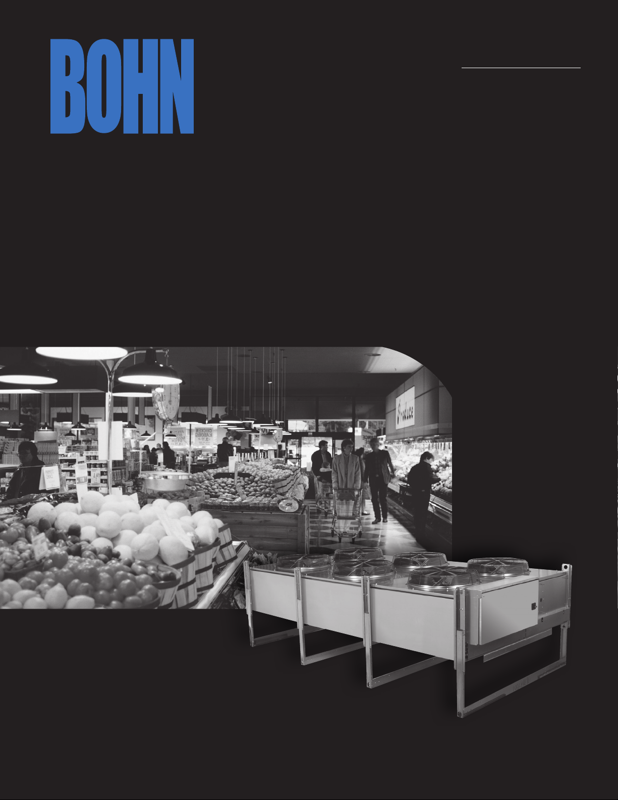
The 3-Phase A/C Series of condensers by Bohn is
designed specically with the growing needs of the
supermarket and grocery industry in mind. This series
utilizes 830 and 540 RPM motors and incorporates
advanced features that further improve sound levels
and energy eciencies, as well as provide increased
capacity in a smaller footprint. In addition, there are
new features designed to improve serviceability,
resulting in reduced maintenance costs.
The 3-Phase A/C Series is a perfect t for applications
requiring low sound and energy levels and
optimized capacities.
Since product improvement is a continuing eort, we reserve the
right to make changes in specications without notice.
2
1140 Series
Bohn continues to oer the 1140 RPM Series for
customers seeking the most economical solution for
their capacity requirements.
Bohn condensers now incorporate a broader product
range with capacities ranging from 11 to 265 nominal
tons to address all applications.
All Bohn condenser coils incorporate the Floating Tube
coil design, which virtually eliminates the possibility
of tube sheet leaks. Condenser coils are designed for
maximum heat transfer and are designed to operate
with most common refrigerants.
© 2015, Heatcraft Refrigeration Products LLC
Page 3
OVERVIEW (continued)
As with all Bohn products, extensive testing of the
condenser ensures long and trouble-free service life.
The condensers are designed for outdoor application
with housings available in aluminum nish and painted
or unpainted galvanized steel.
The condensers are available in either single or double
wide fan congurations.
The condenser design incorporates the features most
desired in air-cooled condensers. An extensive list of
options and fan cycle control panels complement the
condenser design and allow the condenser to match the
most rigid application requirements.
The Floating Tube Coil Design
Dramatically Reduces Tube Sheet Leaks
FEATURES
The Bohn air-cooled condenser is available in multiple
product tiers and is designed with features to meet
specic customer requirements.
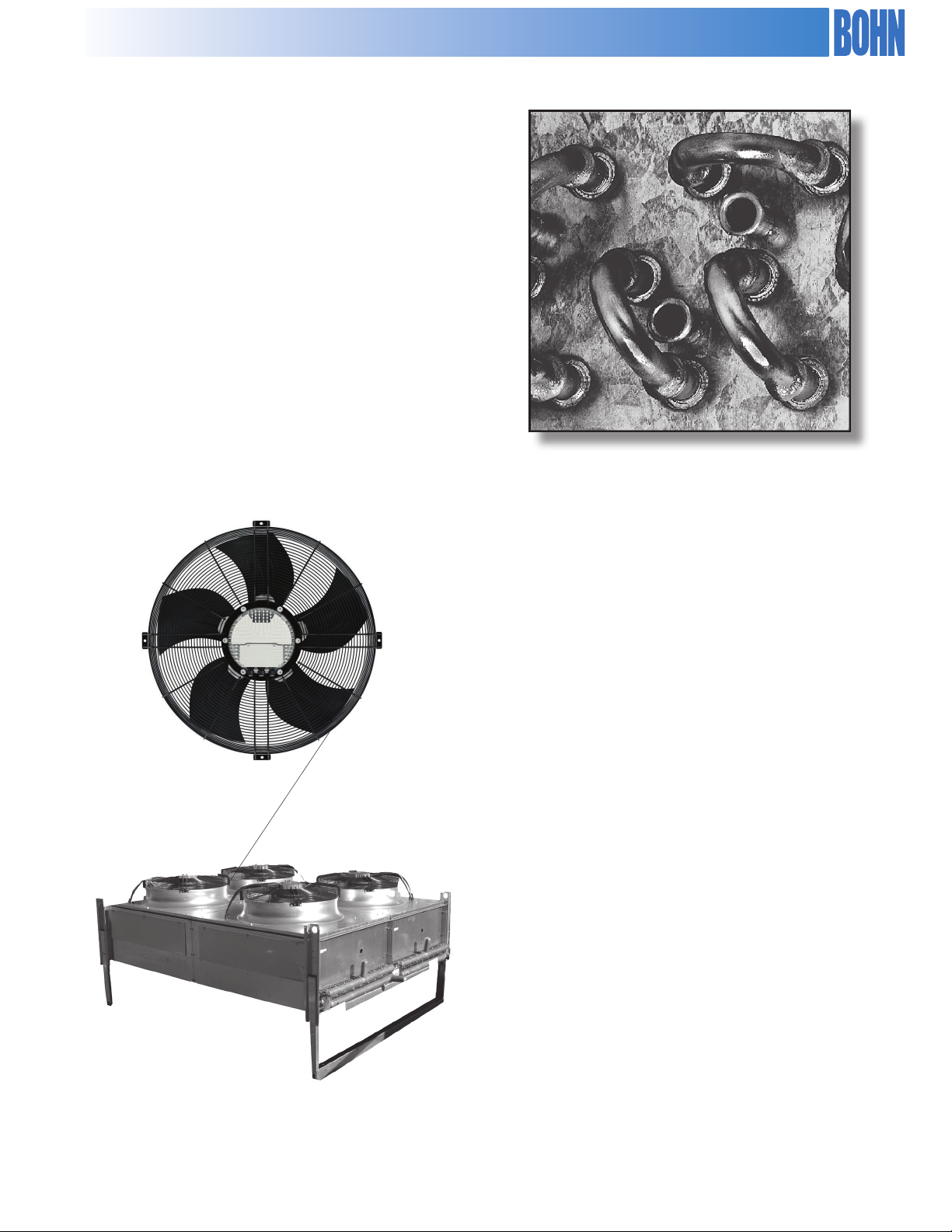
Bohn Venturi Mounted VSEC Series of Condensers
Customers seeking optimum sound and energy
performance can select the Bohn VSEC Series of
condensers with variable speed EC motor technology.
VSEC motors provide unparalleled sound and energy
performance.
Features include:
• VSEC motor, swept fan blade and Venturi
incorporating integrated variable speed technology
• Broad capacity range from 16 to 264 tons
• Aluminum housing for an attractive appearance and
corrosion protection, with painted galvanized steel,
or galvanized steel available as an option
• Side access panels allow for ease of cleaning coils
Venturi Mounted VSEC Series with VSEC Motor Technology
3
Page 4
Bohn 3-Phase A/C Series of Condensers
The 3-Phase A/C Series by Bohn is designed
specically with the growing needs of the
supermarket and grocery industry in mind.
This series utilizes 830 and 540 RPM motors and
incorporates advanced features that further improve
sound levels and energy eciencies, as well as provide
increased capacity in a smaller footprint. In addition,
there are new features designed to improve serviceability,
resulting in reduced maintenance costs. The 3-Phase A/C
Series is a perfect t for applications requiring low sound
and energy levels and optimized capacities.
Features include:
• Direct drive fan motors in 830 or 540 RPM
• The patented QuietEdge fan blade provides an
unprecedented sound level of 49.6 dBA (540 RPM @ 10 ft.)
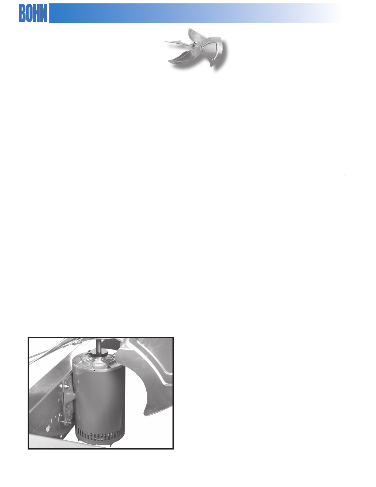
• The Bohn patented (#7, 210, 661) ServiceEase motor
mount feature allows for ease of motor service and
reduces likelihood of damage to the coils during
servicing
• Bohn condenser coils incorporate the latest coil
technology to provide maximum capacity
• Broader product range to address all applications
capacities ranging from 11 to 225 nominal tons
• Galvanized steel cabinet with the option for
aluminum or painted galvanized steel
• High eciency, three-phase fan motors with ball
bearings and internal overload protection
1140 Series
For customers seeking an economical solution to
their capacity needs, Bohn now oers the 1140 RPM
Series with enhancements to improve capacity and
serviceability.
Bohn's Patented QuietEdge Fan Blade for
Improved Sound Performance
Features include:
• Direct drive fan motors
• The Bohn patented (#7, 210, 661) ServiceEase™ motor
mount
• New, high eciency condenser coil designed for
optimum performance
• Expanded product range from 15 to 249 nominal tons
• Galvanized steel as a standard housing, with an option
for aluminum or painted galvanized steel
• High eciency, three-phase fan motors with ball
bearings and internal overload protection
All Standard Condensers
• 10 ns per inch spacing
• Modular design with models in both single and
double wide fan congurations
• All Bohn condensers incorporate the Floating Tube
coil design, which virtually eliminates tube sheet leaks
• Internal baes provided between all fan cells
• Condensers up to 3 fans in length use 3/8” diameter
tube to minimize refrigerant charge. Condensers
4 or more fans in length use 1/2" diameter tube to
minimize refrigerant pressure drop
• Coated steel fan guards
• Weatherproof control panel with factory-mounted
door interrupt disconnect switch
• UL and UL listed for Canada
Available Options:
• Multi-circuiting at no additional charge
• Optional 8, 12 or 14 FPI spacing
• Fan-cycle control panels
• Alternate coil construction including BohnGuard coated
ns, epoxy or phenolic coated ns and copper ns
• Hinged fan panels for ease of servicing (3-Phase A/C
and 1140 Series only)
• Side access panels
• Extended condenser legs for increased ground clearance
• Sealtite wiring
• Frame for shipping
ServiceEase Motor Mount System
4
Page 5
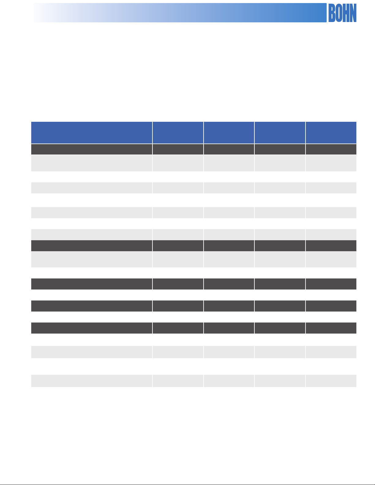
Three Solutions Tailored To Fit Your Unique Needs
Choose from Fixed Speed, Rail Mounted VSEC, or Venturi Mounted VSEC series of
air-cooled condensers by Bohn. Choosing the Venturi Mounted VSEC Series means that
you are selecting the ultimate in capacity, sound, and eciency. The Rail Mounted VSEC
option oers all of the benets of variable speed in a conventional condenser package,
while the xed speed options continue to provide proven performance and capacity.
FEATURE
1140 RPM
FIXED SPEED
830 & 540 RPM
FIXED SPEED
RAIL MOUNTED
VSEC
VENTURI
MOUNTED VSEC
Motors
Standard Motor 1140 RPM 830, 540 RPM
P66 Motor Option
Cabinet
Standard Cabinet Galvanized Galvanized Galvanized Aluminum
Galvanized Option (standard) (standard) (standard)
Pre-Painted Galvanized Option
Aluminum Option
Venturi Cover
Standard Venturi Removable Removable Removable
Hinged Option
Fan Blades
Standard Blade Standard QuietEdge™ Standard/QuietEdge
Motor Mounted
p p
p p p p
p p p
p p p
Variable Speed
EC Motors
TM
Variable Speed
EC Motors
(standard)
EC Tall
Optimized
EC Optimized
p
-
Standard Motor Mounted Service Ease™ Service Ease™ Service Ease™ EC Optimized
Warranty
Two-Year Warranty
Two-Year Warranty - Rail Mounted VSEC Motors - -
Three-Year Warranty - Venturi Mounted VSEC Motors - - -
Five-Year Warranty - Floating TUBE ™ Coil Design
p p p p
p
p
p p p p
-
5
Page 6
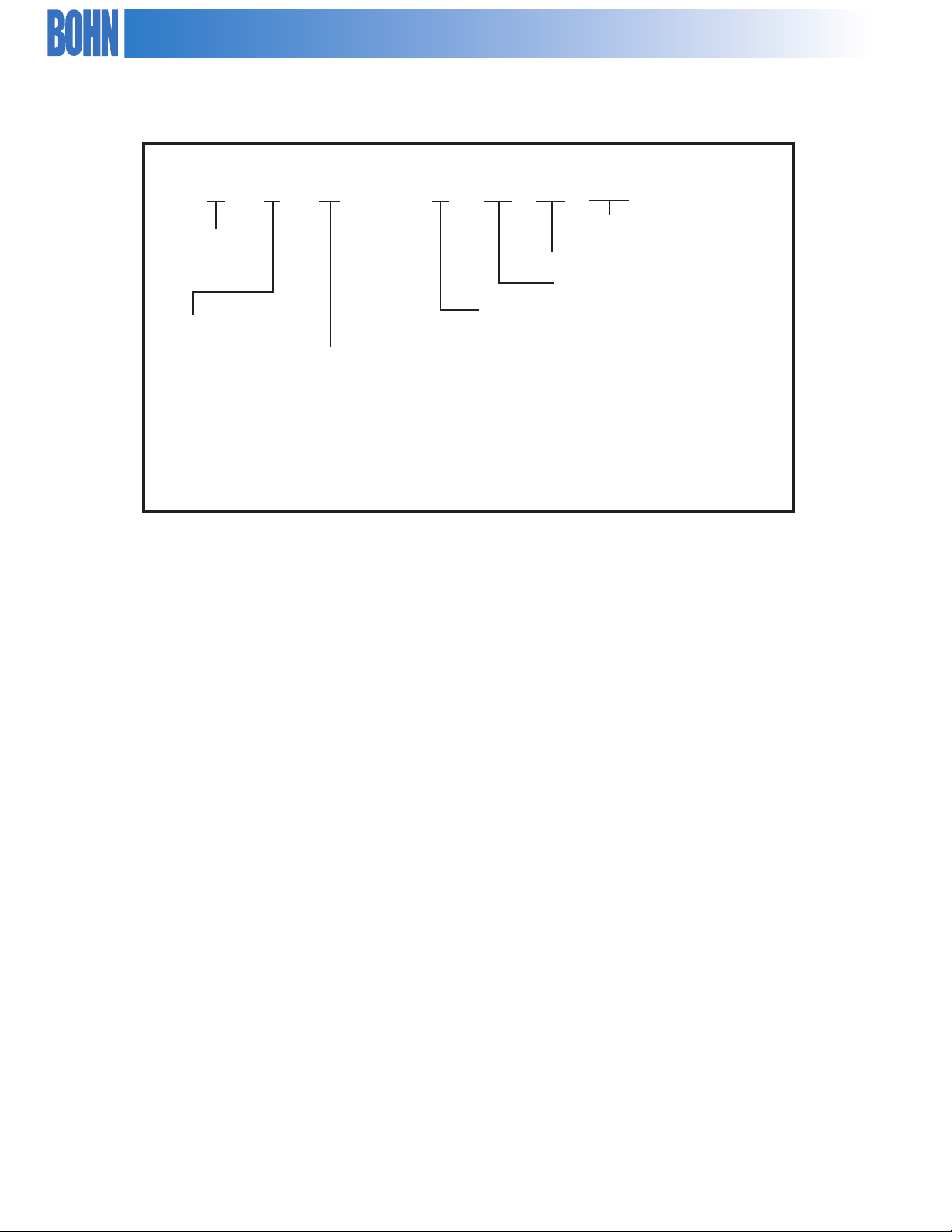
NOMENCLATURE
B N H – S 04 A 050
B - Bohn
N – Vintage
Model Identier
Fans
Width
S – Single Wide
Motor
H - 1140 RPM 1.5 HP
L - 830 RPM, 1.5 HP
X - 830 RPM, 1.0 HP
Q - 540 RPM, 0.5 HP
E - Venturi Mounted VSEC, 2.0 HP
J - Rail Mounted VSEC, 830 RPM, 2.5 HP
K - Rail Mounted VSEC, 1140 RPM, 2.25 HP
D – Double Wide
01-14
Standard Capacity
(MBH/°TD, R-22 @ 10 FPI)
6
Page 7
Condenser Selection
Capacity for air-cooled condensers are based on Total Heat of Rejection (THR)
at the condenser. Total heat of rejection is equal to net refrigeration at the
evaporator (compressor capacity) plus the energy input into the refrigerant
by the compressor (heat of compression). The heat of compression will
vary depending on the compressor manufacturer, type of compressor
and the operating conditions of the compressor. Whenever possible, it is
recommended that you obtain the heat of compression value from the
compressor manufacturer.
If this is not available, the THR can be estimated using the following formula:
THR = (Compressor Capacity) * (Heat of Compression Factor, Tables 1 & 2)
Table 1 contains heat of compression factors for suction cooled compressors
and Table 2 contains factors for open drive compressors. For refrigeration
systems beyond the range of Tables 1 and 2, use the following equations to
estimate THR:
Open Compressors:
THR = Compressor Capacity (BTUH) + (2545) * (Break Horsepower, BHP)
Suction Cooled Compressors:
THR = Compressor Capacity (BTUH) + (3413 * KW)
The compressor capacity is eected by its altitude. If the condenser location
is above sea level, an additional correction is required to the THR, as follows:
THR (altitude) = THR * Altitude Correction Factor, Table 3
Selection Example
Compressor capacity: 350,000
Evaporator temperature: +25° F
Condensing temperature: 115° F
Ambient temperature 95° F
Refrigerant: R-22
Compressor type: Semi-hermetic, suction cooled
Condenser type: 540 RPM, one row of fans
Condenser altitude: 1,000 feet
Step 1: Estimate Condenser THR
From Table 1 for suction cooled compressors, at +25° F suction, we need to
determine the heat of compression factor for 115° F condensing temperature
(NOT shown in table).
Therefore, select the condensing temperatures and heat of compression
factor for +25° F suction temperatures as follows:
100° 115° 110° (Condensing Temperature)
1.31 X 1.36 (Heat of Compression Factor)
To determine X: (Heat of Compression Factor)
((1.36-X) / (1.36-1.31)) = ((120-115) / (120-110)) = ((1.36-X)/0.05) = (5/10)
X = 1.36 – (0.05 * 0.5) = 1.335
Therefore heat of compression factor at 115° F condensing temperature is
1.335
THR = Compressor Capacity * Heat of Compression Factor
= 350,000 * 1.335
= 467,250
Step 2: Correct for Altitude
From Table 3 obtain an altitude correction factor of 1.02 for 1,000 feet.
THR = THR (from step 1) * Altitude Correction Factor (design)
= 467,250 * 1.02
= 476,595
Step 3: Calculate Design Condenser T.D.
Design Condenser T.D. = Condensing Temp — Ambient Temp
= 115 - 95
= 20° T.D.
Step 4: Condenser Selection
Condenser capacities for condensers at 540 RPM are located in Table 7. These
capacities are given in MBH/°TD. Convert the THR calculated in step 2 to
MBH/°TD by dividing by 1,000 to get THR in MBH. Then divide the THR by the
design TD to get MBH/°TD.
THR (MBH) = 476,595 / 1,000 = 476.6
THR (MBH/°TD) = 476.6 / 20 = 23.83
Locate the 10 FPI column for R-22 refrigerant and read down until you locate a
value equal to or just larger than 23.83. This value is 25.9. Read horizontally to
the left to obtain a condenser model of BNQ-S05-A026.
Step 5: Calculate Actual T.D. and Condensing Temperature
The actual condenser T.D. can be calculated by dividing the design THR by
the condenser rating.
Actual T.D. = THR (Design) / (Rating @ 1° T.D.)
= 476.6 / 25.9
= 18.4°F. T.D.
The actual condensing temperature is the actual T.D. plus the ambient
temperature. Actual Condensing Temperature = (Actual T.D.) + (Ambient)
= 18.4 + 95
= 113.4°F.
Table 1. Heat of Compression Factor for Suction Cooled Compressors.
Suction
Temp. °F
-40° 1.56 1.63 1.72 1.81 1.94
-30° 1.49 1.55 1.62 1.7 1.8
-20° 1.43 1.49 1.55 1.62 1.7
-10° 1.38 1.43 1.49 1.55 1.63
0° 1.34 1.38 1.43 1.49 1.56
5° 1.31 1.36 1.41 1.48 1.55
10° 1.29 1.34 1.39 1.44 1.52
15° 1.26 1.31 1.36 1.41 1.48
20° 1.24 1.28 1.33 1.38 1.44
25° 1.22 1.26 1.31 1.36 1.42
30° 1.2 1.24 1.28 1.33 1.39
40° 1.17 1.2 1.24 1.28 1.33
50° 1.13 1.16 1.2 1.24 1.28
90° 100° 110° 120° 130°
Condensing Temp erature °F
Table 2. Heat of Compression Factor for Open Drive Compressors.
Evaporator
Temp. °F
-30° 1.37 1.42 1.47 — — —
-20° 1.33 1.37 1.42 1.47 — —
-10° 1.28 1.32 1.37 1.42 1.47 —
0° 1.24 1.28 1.32 1.37 1.41 1.47
5° 1.23 1.26 1.3 1.35 1.39 1.45
10° 1.21 1.24 1.28 1.32 1.36 1.42
15° 1.19 1.22 1.26 1.3 1.34 1.4
20° 1.17 1.2 1.24 1.28 1.32 1.37
25° 1.16 1.19 1.22 1.26 1.3 1.35
30° 1.14 1.17 1.2 1.24 1.27 1.32
40° 1.12 1.15 1.17 1.2 1.23 1.28
50° 1.09 1.12 1.14 1.17 1.2 1.24
90° 100° 110° 120° 130° 140°
Condensing Temperature °F
Table 3. Altitude Correction Factors.
Altitude Correction Factor
0 1
1,000 1.02
2,000 1.05
3,000 1.07
4,000 1.1
5,000 1.12
6,000 1.15
7,000 1.17
7
Page 8

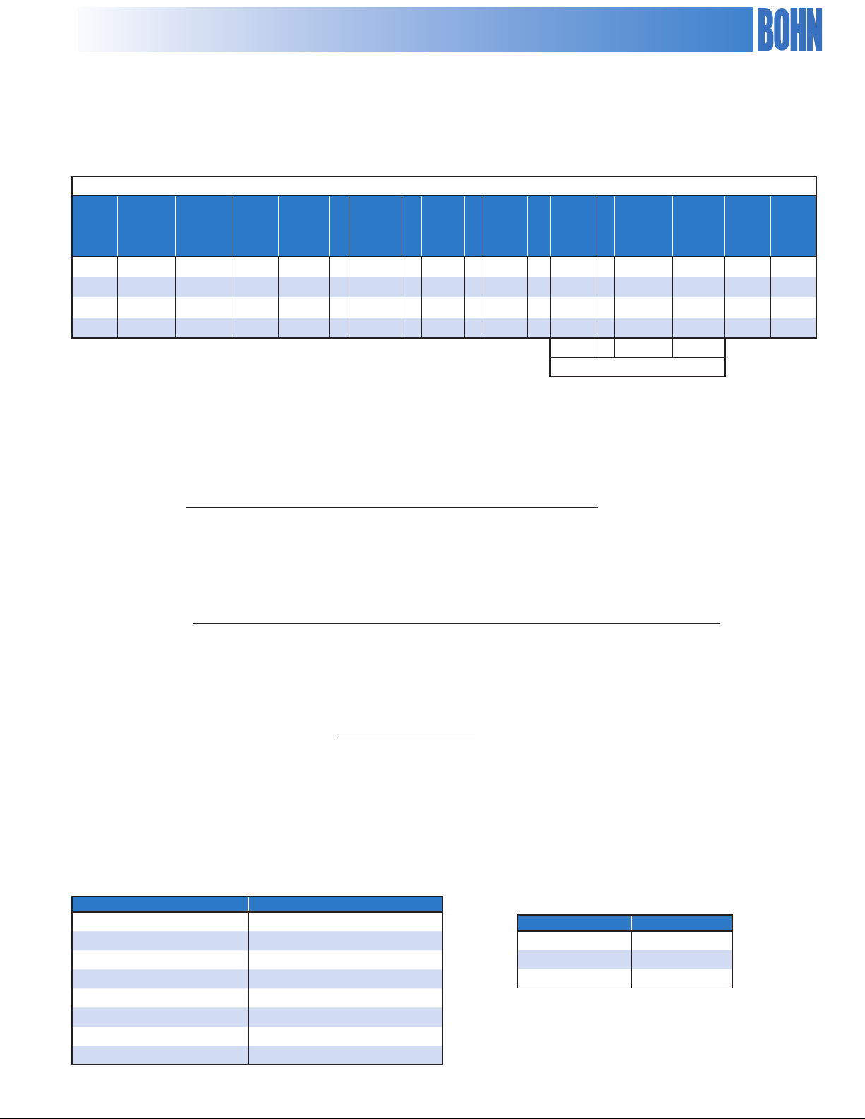
Multi-Circuiting Selection
Multi-Circuiting Selection Procedure
The air-cooled condensers are available with more than one
refrigerant circuit. The condenser will be factory assembled with the
condenser coil divided into individual refrigerant circuits, each sized
Multi-Circuit Condenser Selection
Given four suction cooled compressors with conditions shown in Table
4. The condenser shall have 830 RPM, 1.0 HP fan motors,
Selection Procedure
Step 1: Input customer data in Table 4 in columns 1, 2, 3, 4
and 5.
Step 2: From Table 1, select the heat of compression factor
for suction cooled compressors and input into
Column #6.
Step 3: From Table 3 obtain the altitude correction factor
and input into Column #7.
Step 4: From Table 5 obtain the refrigerant capacity factor and
input into Column #8.
for its own specic application. Each circuit is supplied with its own
inlet and outlet connections, individually labeled.
with two rows of fans. The condenser location is at 3,000 ft. and the
design ambient is 95°F.
Step 5: Calculate the design T.D. for each circuit by
subtracting the ambient temperature from the circuit
design condensing temperature and input into
Column #9.
T.D. = Design Condensing Temperature - Ambient Temperature
Step 6: Calculate the design THR / °T.D. for each circuit.
Multiply Column #5 by Column #6 and Column #7 to
calculate the THR for each circuit. Divide the result by
the refrigerant correction factor, Column #8 to convert
the capacities to a common refrigerant. Divide the
result by the design T.D., Column #9 to calculate the
design THR / °T.D. and input into Column #10.
Design THR / °T.D. = Compressor Capacity (#5) * Heat of Compressor Factor (#6) x Altitude Factor (#7)
Refrigerant Capacity Factor (#8) * Design T.D. (#9)
Example for Circuit #1:
Design THR / °T.D. = 235,000 * 1.31 * 1.07
1.02 x 15
= 21,529 BTUH / °T.D.
Step 7: Add the design THR / °T.D. for each circuit in column
#10, to get a total of 39,578 BTUH / °T.D. Divide this
total by 1,000 to get 39.6 MBH / °T.D.
Step 8: From Table 10 for two rows of condenser fans with
830 RPM, 1.0 HP fan motors, locate the column for
R-404A capacity with 10 FPI. Read down the column
until you get to a capacity equal to or greater than 39.6
MBH / °T.D. This value is 44.5 which corresponds to a
BNX-D06-A045. From Table 12 obtain the total
number of feeds available as 56.
8
Page 9
Multi-Circuiting Condenser
Table 4. Condenser Multi-Circuit Selection
1 2 3 4 5 X 6 X 7 ÷ 8 ÷ 9 = 10 11 12 13
X
Heat of
Com-
press.
Factor
X
Alti-
tude
Factor
÷
Refrig.
Cap.
Factor
Design
÷
Cond.
T.D .
TOTAL = 39,578 56
39,578 / 1,000 = 39.6 MBH/°TD
=
Design
THR/°TD
No. of
Feeds
Per Circ.
Actual
Cond.
Circuit
Name
Step 9: Determine the number of feeds per circuit. Divide the design THR / °T.D. in Column #10 by the total capacity required (39,578) and
Evap.
Temp.°F
1 25 110 22 235,000 X 1.31 X 1.07 ÷ 1.02 ÷ 15 = 21,529 31 13.1 108.1
2 20 110 134a 61,000 X 1.33 X 1.07 ÷ .97 ÷ 15 = 5,966 8 14.1 109.1
3 -10 105 22 31,000 X 1.46 X 1.07 ÷ 1.02 ÷ 10 = 4,748 7 8.5 103.5
4 -20 105 22 46,000 X 1.52 X 1.07 ÷ 1.02 ÷ 10 = 7,335 10 9.2 104.2
multiply this result by the number of feeds available, which is 56. Round this value to the nearest integer and place in Column #11
Add the individual feeds per circuit to get a total number of feeds for the condenser. This total must equal the total number of
feeds available for the condenser (56).
Design
Cond.
Temp.°F
Comp.
Refrig.
Type
Cap.
BTUH
T.D .
Actual
Cond.
Temp.
°F
Number of = Design THR / °T.D.(#10) * Number of Circuits Available (56)
feeds/circuit Total Capacity Required (39,578)
Step 10: Calculate actual condensing T.D., (ATD):
ATD = Design T.D. (#9) * Design THR/°T.D. (#10) * Number of Feeds Available (56)
Number Feeds / CIR (#11) * Condenser Capacity / °T.D. (Step #8) * 1,000
Example for Circuit #1:
ATD = 15 * 21,529 x 56
= 13.1°F.
31 * 44.5 * 1,000
Input these T.D. values in column #12.
Step 11: Calculate the actual condensing temperature. Actual condensing temperature is equal to the actual condensing T.D., Column #12
plus the design ambient (95°). Input these values in Column #13. If the actual condensing temperature for each circuit is too high,
it may be necessary to adjust the number of feeds per circuit or to select the next larger condenser size and recalculate the number
of feeds per circuit.
Table 5. Refrigerant Capacity Factor.
Refrigerant Capacity Factor
R-22 1.02
R-134a 0.99
R-404A 1
R-407A 0.98*
R-407C 0.94*
R-407F 0.98*
R-410A 1.02
R-507 1
Table 6. Voltage Frequency
Capacity Factor
Frequency Capacity Factor
60 Hz 1.0
50 Hz (H, L, X, Q) 0.92
50 Hz (E) 1.0
*Correction factors based on midpoint condensing temperature.
9
Page 10
CONDENSER CAPACITY
Table 7. BNQ Models, 540 RPM, 0.5 HP, 30" Fan Diameter
R22 / R410A
Model
8 FPI 10 FPI 12 FPI 14 FPI 8 FPI 10 FPI 12 FPI 14 FPI
MBH / 1° TD
BNQ 540 830 VSEC 1140
R404A/R507
MBH / 1° TD
BNQ-S01-A005
BNQ-S01-A006
BNQ-S02-A008
BNQ-S02-A010
BNQ-S02-A011
BNQ-S03-A016
BNQ-S03-A017
BNQ-S04-A021
BNQ-S04-A023
BNQ-S05-A026
BNQ-S05-A029
BNQ-S06-A034
BNQ-S07-A042
4.6 5.2 5.6 5.9 4.6 5.1 5.5 5.8
5.5 6.1 6.4 6.6 5.4 5.9 6.2 6.5
7.2 8.0 8.7 9.1 7.0 7.8 8.5 8.9
9.4 10.3 10.8 11.8 9.2 10.1 10.6 11.6
10.8 11.5 11.9 12.3 10.6 11.2 11.7 12.0
14.1 15.6 16.2 16.9 13.8 15.2 15.9 16.6
16.2 17.2 17.9 19.8 15.9 16.9 17.5 19.4
18.8 20.7 21.6 23.5 18.4 20.3 21.2 23.0
21.6 22.9 23.8 24.5 21.2 22.4 23.3 24.0
23.5 25.9 27.0 29.3 23.1 25.4 26.4 28.8
27.0 28.6 29.8 30.7 26.5 28.1 29.2 30.1
32.4 34.4 35.7 36.8 31.8 33.7 35.0 36.1
38.4 41.6 42.8 44.3 37.7 40.7 41.9 43.4
BNQ-D04-A016
BNQ-D04-A021
BNQ-D04-A023
BNQ-D06-A031
BNQ-D06-A034
BNQ-D08-A041
BNQ-D08-A046
BNQ-D10-A052
BNQ-D10-A057
BNQ-D12-A069
BNQ-D14-A083
BOLD indicates standard model capacity.
* Data based on mid point condensing temperature
14.3 16.0 17.3 18.2 14.0 15.6 16.9 17.9
18.8 20.7 21.6 23.6 18.4 20.3 21.2 23.2
21.6 22.9 23.8 24.5 21.2 22.4 23.3 24.0
28.2 31.0 32.4 33.8 27.6 30.4 31.8 33.1
32.4 34.4 35.7 39.5 31.8 33.7 35.0 38.7
37.6 41.4 43.2 47.0 36.9 40.6 42.3 46.1
43.2 45.8 47.6 49.0 42.4 44.9 46.7 48.1
47.0 51.8 54.0 58.7 46.1 50.7 52.9 57.5
54.0 57.3 59.5 61.3 53.0 56.1 58.3 60.1
64.8 68.7 71.4 73.6 63.6 67.3 70.0 72.1
76.8 83.1 85.5 88.6 75.3 81.5 83.8 86.8
10
Page 11
CONDENSER CAPACITY
Table 8. BNQ Models, 540 RPM, 0.5 HP, 30" Fan Diameter
R407A / R407F*
Model
8 FPI 10 FPI 12 FPI 14 FPI 8 FPI 10 FPI 12 FPI 14 FPI
MBH / 1° TD
BNQ 540 830 VSEC 1140
R407C*
MBH / 1° TD
BNQ-S01-A005
BNQ-S01-A006
BNQ-S02-A008
BNQ-S02-A010
BNQ-S02-A011
BNQ-S03-A016
BNQ-S03-A017
BNQ-S04-A021
BNQ-S04-A023
BNQ-S05-A026
BNQ-S05-A029
BNQ-S06-A034
BNQ-S07-A042
4.5 5.0 5.4 5.7 4.3 4.8 5.2 5.5
5.3 5.8 6.1 6.3 5.1 5.6 5.9 6.1
6.9 7.6 8.3 8.7 6.6 7.3 8.0 8.4
9.0 9.9 10.4 11.3 8.7 9.5 10.0 10.9
10.4 11.0 11.4 11.8 10.0 10.6 11.0 11.3
13.5 14.9 15.6 16.2 13.0 14.3 14.9 15.6
15.6 16.5 17.1 19.0 14.9 15.8 16.4 18.2
18.1 19.9 20.8 22.6 17.3 19.1 19.9 21.6
20.8 22.0 22.9 23.6 19.9 21.1 21.9 22.6
22.6 24.9 25.9 28.2 21.7 23.8 24.9 27.0
25.9 27.5 28.6 29.5 24.9 26.4 27.4 28.3
31.1 33.0 34.3 35.3 29.9 31.7 32.9 33.9
36.9 39.9 41.1 42.5 35.4 38.3 39.4 40.8
BNQ-D04-A016
BNQ-D04-A021
BNQ-D04-A023
BNQ-D06-A031
BNQ-D06-A034
BNQ-D08-A041
BNQ-D08-A046
BNQ-D10-A052
BNQ-D10-A057
BNQ-D12-A069
BNQ-D14-A083
BOLD indicates standard model capacity.
* Data based on mid point condensing temperature
13.8 15.3 16.6 17.5 13.2 14.7 15.9 16.8
18.1 19.9 20.7 22.7 17.3 19.1 19.9 21.8
20.8 22.0 22.9 23.6 19.9 21.1 21.9 22.6
27.1 29.8 31.1 32.5 26.0 28.6 29.9 31.1
31.1 33.0 34.3 38.0 29.9 31.7 32.9 36.4
36.1 39.8 41.5 45.1 34.6 38.1 39.8 43.3
41.5 44.0 45.7 47.1 39.8 42.2 43.9 45.2
45.2 49.7 51.9 56.4 43.3 47.7 49.7 54.1
51.9 55.0 57.2 58.9 49.8 52.8 54.8 56.5
62.3 66.0 68.6 70.7 59.7 63.3 65.8 67.8
73.8 79.9 82.2 85.1 70.8 76.6 78.8 81.6
11
Page 12
CONDENSER SPECIFICATIONS
BNQ 540 830 VSEC 1140
Table 9. BNQ Models, 540 RPM, 0.5 HP, 30" Fan Diameter
208-230/3/60 460/3/60
Model CFM
FLA MCA MOPD FLA MCA MOPD
BNQ-S01-A005 5,400 3.5 15.0 15 1.8 15.0 15 0.4 1 3/8 7 330
BNQ-S01-A006 5,200 3.5 15.0 15 1.8 15.0 15 0.4 1 3/8 14 360
BNQ-S02-A008 11,200 7.0 15.0 15 3.6 15.0 15 0.9 1 3/8 14 580
BNQ-S02-A010 10,800 7.0 15.0 15 3.6 15.0 15 0.9 1 5/8 21 630
BNQ-S02-A011 10,400 7.0 15.0 15 3.6 15.0 15 0.9 2 1/8 28 680
BNQ-S03-A016 16,100 10.5 15.0 20 5.4 15.0 15 1.3 2 1/8 21 930
BNQ-S03-A017 15,600 10.5 15.0 20 5.4 15.0 15 1.3 2 1/8 28 1,000
BNQ-S04-A021 21,500 14.0 15.0 20 7.2 15.0 15 1.7 2 1/8 21 1,210
Unit
kW
Conn.
(in.)
Max.
No.
of
Feeds
prox.
Weight
(lbs)
Ap-
Net
BNQ-S04-A023 20,800 14.0 15.0 20 7.2 15.0 15 1.7 2 5/8 28 1,310
BNQ-S05-A026 26,900 17.5 20.0 25 9.0 15.0 15 2.2 2 5/8 21 1,510
BNQ-S05-A029 26,000 17.5 20.0 25 9.0 15.0 15 2.2 2 5/8 28 1,640
BNQ-S06-A034 31,200 21.0 21.9 30 10.8 15.0 15 2.6 2 5/8 28 1,950
BNQ-S07-A042 36,400 24.5 25.4 35 12.6 15.0 15 3.1 2 @ 2 5/8 28 2,240
BNQ-D04-A016 22,300 14.0 15.0 20 7.2 15.0 15 1.7 2 @ 1 3/8 28 1,240
BNQ-D04-A021 21,500 14.0 15.0 20 7.2 15.0 15 1.7 2 @ 1 5/8 42 1,340
BNQ-D04-A023 20,800 14.0 15.0 20 7.2 15.0 15 1.7 2 @ 2 1/8 56 1,440
BNQ-D06-A031 32,300 21.0 21.9 30 10.8 15.0 15 2.6 2 @ 2 1/8 42 1,990
BNQ-D06-A034 31,200 21.0 21.9 30 10.8 15.0 15 2.6 2 @ 2 1/8 56 2,140
BNQ-D08-A041 43,000 28.0 28.9 35 14.4 15.0 20 3.5 2 @ 2 1/8 42 2,630
BNQ-D08-A046 41,600 28.0 28.9 35 14.4 15.0 20 3.5 2 @ 2 5/8 56 2,830
BNQ-D10-A052 53,700 35.0 35.9 45 18.0 20.0 20 4.4 2 @ 2 5/8 42 3,290
BNQ-D10-A057 52,100 35.0 35.9 45 18.0 20.0 20 4.4 2 @ 2 5/8 56 3,540
BNQ-D12-A069 62,500 42.0 42.9 50 21.6 22.1 25 5.2 2 @ 2 5/8 56 4,230
BNQ-D14-A083 72,900 49.0 49.9 60 25.2 25.7 30 6.1 4 @ 2 5/8 56 4,910
12
Page 13
CONDENSER CAPACITY
BNX 540 830 VSEC 1140
Table 10. BNX Models, 830 RPM, 1.0 HP, 30" Fan Diameter
R22/R410A
Model
MBH / 1° TD
8 FPI 10 FPI 12 FPI 14 FPI 8 FPI 10 FPI 12 FPI 14 FPI
BNX-S01-A006 5.6 6.4 7.0 7.4 5.5 6.2 6.8 7.3
BNX-S01-A008 6.8 7.5 8.0 8.4 6.6 7.4 7.9 8.3
BNX-S02-A010 8.8 9.8 10.6 11.2 8.6 9.6 10.4 11.0
BNX-S02-A013 12.0 13.1 13.8 14.8 11.8 12.8 13.6 14.5
BNX-S02-A015 14.0 15.1 15.7 16.0 13.7 14.8 15.3 15.7
BNX-S03-A020 18.0 19.7 20.8 21.8 17.7 19.3 20.4 21.4
BNX-S03-A023 21.0 22.7 23.5 25.3 20.5 22.3 23.0 24.8
BNX-S04-A026 24.1 26.3 27.7 29.3 23.6 25.7 27.1 28.7
R404A/R507
MBH / 1° TD
BNX-S04-A030 27.9 30.3 31.3 32.0 27.4 29.7 30.7 31.4
BNX-S05-A033 30.1 32.8 34.6 36.7 29.5 32.1 33.9 36.0
BNX-S05-A038 34.9 37.8 39.2 40.1 34.2 37.1 38.4 39.3
BNX-S06-A045 41.9 45.4 47.0 48.1 41.1 44.5 46.0 47.1
BNX-S07-A052 47.7 52.0 54.8 56.1 46.8 51.0 53.7 55.0
BNX-D04-A020 17.5 19.6 21.2 22.5 17.2 19.2 20.8 22.0
BNX-D04-A026 24.1 26.2 27.7 29.7 23.6 25.7 27.1 29.1
BNX-D04-A030 27.9 30.3 31.3 32.0 27.4 29.7 30.7 31.4
BNX-D06-A039 36.1 39.4 41.5 43.7 35.4 38.6 40.7 42.8
BNX-D06-A045 41.9 45.4 47.0 50.6 41.1 44.5 46.0 49.6
BNX-D08-A052 48.1 52.5 55.4 58.6 47.1 51.4 54.3 57.5
BNX-D08-A061 55.9 60.6 62.7 64.1 54.8 59.3 61.4 62.8
BNX-D10-A066 60.1 65.6 69.2 73.5 58.9 64.3 67.8 72.0
BNX-D10-A076 69.9 75.7 78.3 80.1 68.4 74.2 76.8 78.5
BNX-D12-A091 83.8 90.8 94.0 96.1 82.1 89.0 92.1 94.2
BNX-D14-A104 95.5 104.1 109.6 112.2 93.6 102.0 107.5 110.0
BOLD indicates standard model capacity.
* Data based on mid point condensing temperature
13
Page 14
CONDENSER CAPACITY
BNX 540 830 VSEC 1140
Table 11. BNX Models, 830 RPM, 1.0 HP, 30" Fan Diameter
R407A / R407F*
Model
MBH / 1° TD
8 FPI 10 FPI 12 FPI 14 FPI 8 FPI 10 FPI 12 FPI 14 FPI
BNX-S01-A006 5.4 6.1 6.7 7.1 5.2 5.9 6.4 6.8
BNX-S01-A008 6.5 7.2 7.7 8.1 6.2 6.9 7.4 7.8
BNX-S02-A010 8.4 9.4 10.2 10.8 8.1 9.0 9.8 10.4
BNX-S02-A013 11.6 12.6 13.3 14.3 11.1 12.1 12.7 13.7
BNX-S02-A015 13.4 14.5 15.0 15.4 12.9 13.9 14.4 14.8
BNX-S03-A020 17.3 18.9 19.9 21.0 16.6 18.1 19.1 20.1
BNX-S03-A023 20.1 21.8 22.5 24.3 19.3 20.9 21.6 23.3
BNX-S04-A026 23.1 25.2 26.6 28.2 22.2 24.2 25.5 27.0
R407C*
MBH / 1° TD
BNX-S04-A030 26.8 29.1 30.1 30.8 25.7 27.9 28.9 29.5
BNX-S05-A033 28.9 31.5 33.2 35.3 27.7 30.2 31.9 33.9
BNX-S05-A038 33.5 36.3 37.6 38.5 32.2 34.8 36.1 36.9
BNX-S06-A045 40.2 43.6 45.1 46.1 38.6 41.8 43.3 44.3
BNX-S07-A052 45.9 50.0 52.7 53.9 44.0 47.9 50.5 51.7
BNX-D04-A020 16.8 18.8 20.4 21.6 16.1 18.0 19.6 20.7
BNX-D04-A026 23.1 25.2 26.6 28.5 22.2 24.2 25.5 27.3
BNX-D04-A030 26.8 29.1 30.1 30.8 25.7 27.9 28.9 29.5
BNX-D06-A039 34.7 37.8 39.9 41.9 33.2 36.3 38.3 40.2
BNX-D06-A045 40.2 43.6 45.1 48.6 38.6 41.8 43.3 46.6
BNX-D08-A052 46.2 50.4 53.2 56.3 44.3 48.4 51.0 54.0
BNX-D08-A061 53.7 58.1 60.2 61.5 51.5 55.8 57.7 59.0
BNX-D10-A066 57.8 63.0 66.5 70.6 55.4 60.4 63.8 67.7
BNX-D10-A076 67.1 72.7 75.2 76.9 64.3 69.7 72.1 73.8
BNX-D12-A091 80.5 87.2 90.3 92.3 77.2 83.7 86.6 88.5
BNX-D14-A104 91.7 100.0 105.3 107.8 88.0 95.9 101.0 103.4
BOLD indicates standard model capacity.
* Data based on mid point condensing temperature
14
Page 15

CONDENSER SPECIFICATIONS
BNX 540 830 VSEC 1140
Table 12. 3-Phase A/C BNX Models, 830 RPM, 1.0 HP, 30" Fan Diameter
208-230/3/60 460/3/60
Model CFM
BNX-S01-A006 7,600 4.8 15.0 15 2.4 15.0 15 1.1 1 3/8 7 330
BNX-S01-A008 7,300 4.8 15.0 15 2.4 15.0 15 1.1 1 3/8 14 360
BNX-S02-A010 15,900 9.6 15.0 20 4.8 15.0 15 2.2 1 3/8 14 580
BNX-S02-A013 15,200 9.6 15.0 20 4.8 15.0 15 2.2 1 5/8 21 630
BNX-S02-A015 14,700 9.6 15.0 20 4.8 15.0 15 2.2 2 1/8 28 680
BNX-S03-A020 22,900 14.4 20.0 25 7.2 15.0 15 3.4 2 1/8 21 930
BNX-S03-A023 22,000 14.4 20.0 25 7.2 15.0 15 3.4 2 1/8 28 1,000
BNX-S04-A026 29,800 19.2 20.4 30 9.6 15.0 15 4.5 2 1/8 21 1,210
FLA MCA MOPD FLA MCA MOPD
Unit
kW
Conn.
(in.)
Max.
No.
of
Feeds
Approx.
Net Wt.
(lbs)
BNX-S04-A030 28,400 19.2 20.4 30 9.6 15.0 15 4.5 2 5/8 28 1,310
BNX-S05-A033 37,300 24.0 25.2 35 12.0 15.0 15 5.6 2 5/8 21 1,510
BNX-S05-A038 35,500 24.0 25.2 35 12.0 15.0 15 5.6 2 5/8 28 1,640
BNX-S06-A045 42,600 28.8 30.0 40 14.4 15.0 20 6.7 2 5/8 28 1,950
BNX-S07-A052 49,700 33.6 34.8 45 16.8 20.0 20 7.8 2 @ 2 5/8 28 2,240
BNX-D04-A020 31,700 19.2 20.4 30 9.6 15.0 15 4.5 2 @ 1 3/8 28 1,240
BNX-D04-A026 30,500 19.2 20.4 30 9.6 15.0 15 4.5 2 @ 1 5/8 42 1,340
BNX-D04-A030 29,300 19.2 20.4 30 9.6 15.0 15 4.5 2 @ 2 1/8 56 1,440
BNX-D06-A039 45,700 28.8 30.0 40 14.4 15.0 20 6.7 2 @ 2 1/8 42 1,990
BNX-D06-A045 44,000 28.8 30.0 40 14.4 15.0 20 6.7 2 @ 2 1/8 56 2,140
BNX-D08-A052 59,700 38.4 39.6 50 19.2 20.0 25 8.9 2 @ 2 1/8 42 2,630
BNX-D08-A061 56,800 38.4 39.6 50 19.2 20.0 25 8.9 2 @ 2 5/8 56 2,830
BNX-D10-A066 74,600 48.0 49.2 60 24.0 24.6 30 11.2 2 @ 2 5/8 42 3,290
BNX-D10-A076 71,000 48.0 49.2 60 24.0 24.6 30 11.2 2 @ 2 5/8 56 3,540
BNX-D12-A091 85,200 57.6 58.8 70 28.8 29.4 35 13.4 2 @ 2 5/8 56 4,230
BNX-D14-A104 99,400 67.2 68.4 80 33.6 34.2 40 15.6 4 @ 2 5/8 56 4,910
15
Page 16

CONDENSER CAPACITY
BNL 540 830 VSEC 1140
Table 13. BNL Models, 830 RPM, 1.5 HP, 30" Fan Diameter
R22 / R410A
Model
MBH / 1° TD
8 FPI 10 FPI 12 FPI 14 FPI 8 FPI 10 FPI 12 FPI 14 FPI
BNL-S01-A007 5.9 6.7 7.3 7.9 5.8 6.6 7.2 7.7
BNL-S01-A008 7.2 8.0 8.6 9.0 7.0 7.8 8.4 8.8
BNL-S02-A010 9.1 10.1 11.0 11.7 8.9 9.9 10.8 11.4
BNL-S02-A014 12.6 13.9 14.9 15.7 12.4 13.6 14.6 15.4
BNL-S02-A016 15.0 16.1 16.8 17.6 14.7 15.8 16.5 17.3
BNL-S03-A021 18.9 20.9 22.3 23.4 18.6 20.5 21.8 23.0
BNL-S03-A024 22.5 24.2 25.2 26.9 22.0 23.8 24.7 26.3
BNL-S04-A028 25.3 27.8 29.7 31.2 24.8 27.3 29.1 30.6
BNL-S04-A032 30.0 32.3 33.6 35.2 29.4 31.7 32.9 34.5
R404A/R507
MBH / 1° TD
BNL-S05-A035 32.1 35.5 37.4 39.0 31.4 34.7 36.6 38.2
BNL-S05-A042 38.4 41.6 43.4 44.7 37.7 40.8 42.5 43.8
BNL-S06-A050 46.1 49.9 52.1 53.6 45.2 48.9 51.0 52.6
BNL-S07-A055 50.5 55.0 58.0 60.2 49.5 53.9 56.8 59.0
BNL-D04-A020 18.1 20.2 22.0 23.3 17.7 19.8 21.5 22.9
BNL-D04-A028 25.3 27.8 29.7 31.4 24.8 27.3 29.1 30.7
BNL-D04-A032 30.0 32.3 33.6 35.2 29.4 31.7 32.9 34.5
BNL-D06-A042 37.9 41.8 44.5 46.9 37.2 40.9 43.7 45.9
BNL-D06-A048 45.0 48.4 50.4 53.7 44.1 47.5 49.4 52.7
BNL-D08-A056 50.6 55.7 59.4 62.4 49.6 54.6 58.3 61.1
BNL-D08-A065 60.0 64.6 67.2 70.4 58.8 63.3 65.8 69.0
BNL-D10-A071 64.2 70.9 74.7 78.0 62.9 69.5 73.2 76.5
BNL-D10-A083 76.9 83.1 86.8 89.4 75.3 81.5 85.0 87.6
BNL-D12-A100 90.4 99.8 104.1 107.3 92.2 97.8 102.0 105.1
BNL-D14-A110 101.1 110.0 116.0 120.3 99.1 107.9 113.7 117.9
BOLD indicates standard model capacity.
* Data based on mid point condensing temperature
16
Page 17

CONDENSER CAPACITY
BNL 540 830 VSEC 1140
Table 14. BNL Models, 830 RPM, 1.5 HP, 30" Fan Diameter
R407A / R407F*
Model
MBH / 1° TD
8 FPI 10 FPI 12 FPI 14 FPI 8 FPI 10 FPI 12 FPI 14 FPI
BNL-S01-A007 5.7 6.5 7.0 7.6 5.5 6.2 6.8 7.2
BNL-S01-A008 6.9 7.7 8.2 8.6 6.6 7.3 7.9 8.3
BNL-S02-A010 8.7 9.7 10.6 11.2 8.3 9.3 10.1 10.8
BNL-S02-A014 12.1 13.4 14.3 15.1 11.6 12.8 13.7 14.4
BNL-S02-A016 14.4 15.5 16.1 16.9 13.8 14.9 15.5 16.2
BNL-S03-A021 18.2 20.1 21.4 22.5 17.5 19.2 20.5 21.6
BNL-S03-A024 21.6 23.3 24.2 25.8 20.7 22.3 23.2 24.8
BNL-S04-A028 24.3 26.7 28.5 30.0 23.3 25.6 27.4 28.7
BNL-S04-A032 28.8 31.0 32.3 33.8 27.6 29.8 31.0 32.4
R407C*
MBH / 1° TD
BNL-S05-A035 30.8 34.0 35.9 37.5 29.6 32.7 34.4 35.9
BNL-S05-A042 36.9 39.9 41.7 42.9 35.4 38.3 40.0 41.2
BNL-S06-A050 44.3 47.9 50.0 51.5 42.5 45.9 48.0 49.4
BNL-S07-A055 48.5 52.8 55.7 57.8 46.6 50.7 53.4 55.4
BNL-D04-A020 17.4 19.4 21.1 22.4 16.7 18.6 20.2 21.5
BNL-D04-A028 24.3 26.7 28.5 30.1 23.3 25.6 27.4 28.9
BNL-D04-A032 28.8 31.0 32.3 33.8 27.6 29.8 30.9 32.4
BNL-D06-A042 36.4 40.1 42.8 45.0 34.9 38.5 41.0 43.2
BNL-D06-A048 43.2 46.5 48.4 51.6 41.4 44.6 46.4 49.5
BNL-D08-A056 48.6 53.5 57.1 59.9 46.6 51.3 54.8 57.5
BNL-D08-A065 57.6 62.1 64.5 67.6 55.3 59.5 61.9 64.8
BNL-D10-A071 61.6 68.1 71.8 74.9 59.1 65.3 68.9 71.9
BNL-D10-A083 73.8 79.8 83.3 85.8 70.8 76.6 79.9 82.3
BNL-D12-A100 90.4 95.8 99.9 103.0 86.7 91.9 95.9 98.8
BNL-D14-A110 97.1 105.7 111.4 115.6 93.1 101.4 106.9 110.9
BOLD indicates standard model capacity.
* Data based on mid point condensing temperature
17
Page 18

CONDENSER SPECIFICATIONS
Table 15. BNL Models, 830 RPM, 1.5 HP, 30" Fan Diameter
BNL 540 830 VSEC 1140
208-230/3/60 460/3/60 575/3/60
Model CFM
UnitkWConn.
(in.)
FLA MCA MOPD FLA MCA MOPD FLA MCA MOPD
BNL-S01-A007 8,400 6.6 15.0 25 3.3 15.0 15 2.6 15.0 15 1.4 1 3/8 7 330
BNL-S01-A008 8,000 6.6 15.0 25 3.3 15.0 15 2.6 15.0 15 1.4 1 3/8 14 360
BNL-S02-A010 17,500 13.2 15.0 30 6.6 15.0 15 5.2 15.0 15 2.7 1 3/8 14 580
BNL-S02-A014 16,700 13.2 15.0 30 6.6 15.0 15 5.2 15.0 15 2.7 1 5/8 21 630
BNL-S02-A016 16,100 13.2 15.0 30 6.6 15.0 15 5.2 15.0 15 2.7 2 1/8 28 680
BNL-S03-A021 25,100 19.8 21.5 35 9.9 15.0 15 7.8 15.0 15 4.1 2 1/8 21 930
BNL-S03-A024 24,100 19.8 21.5 35 9.9 15.0 15 7.8 15.0 15 4.1 2 1/8 28 1,000
BNL-S04-A028 32,800 26.4 28.1 45 13.2 15.0 20 10.4 15.0 15 5.4 2 1/8 21 1,210
BNL-S04-A032 31,200 26.4 28.1 45 13.2 15.0 20 10.4 15.0 15 5.4 2 5/8 28 1,310
BNL-S05-A035 41,000 33.0 34.7 50 16.5 20.0 25 13.0 15.0 20 6.8 2 5/8 21 1,510
Max.
No.
of
Feeds
Approx.
Net
Weight
(lbs)
BNL-S05-A042 39,100 33.0 34.7 50 16.5 20.0 25 13.0 15.0 20 6.8 2 5/8 28 1,640
BNL-S06-A050 46,900 39.6 41.3 50 19.8 20.6 25 15.6 20.0 20 8.1 2 5/8 28 1,950
BNL-S07-A055 54,700 46.2 47.9 60 23.1 23.9 30 18.2 20.0 25 9.5
BNL-D04-A020 35,000 26.4 28.1 45 13.2 15.0 20 10.4 15.0 15 5.4
BNL-D04-A028 33,500 26.4 28.1 45 13.2 15.0 20 10.4 15.0 15 5.4
BNL-D04-A032 32,100 26.4 28.1 45 13.2 15.0 20 10.4 15.0 15 5.4
BNL-D06-A042 50,200 39.6 41.3 50 19.8 20.6 25 15.6 20.0 20 8.1
BNL-D06-A048 48,200 39.6 41.3 50 19.8 20.6 25 15.6 20.0 20 8.1
BNL-D08-A056 65,600 52.8 54.5 70 26.4 27.2 35 20.8 21.5 25 10.8
BNL-D08-A065 62,500 52.8 54.5 70 26.4 27.2 35 20.8 21.5 25 10.8
BNL-D10-A071 82,000 66.0 67.7 80 33.0 33.8 40 26.0 26.7 30 13.5
BNL-D10-A083 78,100 66.0 67.7 80 33.0 33.8 40 26.0 26.7 30 13.5
BNL-D12-A100 93,700 79.2 80.9 90 39.6 40.4 45 31.2 31.9 35 16.2
BNL-D14-A110 109,300 92.4 94.1 110 46.2 47.0 50 36.4 37.1 40 18.9
2@2
5/8
2 @ 1
3/8
2 @ 1
5/8
2 @ 2
1/8
2 @ 2
1/8
2 @ 2
1/8
2 @ 2
1/8
2 @ 2
5/8
2 @ 2
5/8
2 @ 2
5/8
2 @ 2
5/8
4 @ 2
5/8
28 2,240
28 1,240
42 1,340
56 1,440
42 1,990
56 2,140
42 2,630
56 2,830
42 3,290
56 3,540
56 4,230
56 4,910
18
Page 19

CONDENSER CAPACITY
BNH 540 830 VSEC 1140
Table 16. Bohn 1140 Series BNH Models, 1140 RPM, 1.5 HP, 30" Fan Diameter
R22 / R410A
Model
MBH / 1° TD
8 FPI 10 FPI 12 FPI 14 FPI 8 FPI 10 FPI 12 FPI 14 FPI
BNH-S01-A007 6.4 7.3 8.0 8.6 6.3 7.2 7.9 8.5
BNH-S01-A009 7.8 8.7 9.5 10.0 7.6 8.6 9.3 9.8
BNH-S02-A011 9.6 10.7 11.7 12.4 9.4 10.5 11.5 12.1
BNH-S02-A015 13.1 14.5 15.6 16.3 12.8 14.2 15.3 16.0
BNH-S02-A017 15.7 17.1 18.1 19.2 15.3 16.7 17.7 18.8
BNH-S03-A022 19.7 21.8 23.4 24.5 19.3 21.4 22.9 24.0
BNH-S03-A026 23.5 25.7 27.1 29.9 23.1 25.2 26.6 29.3
BNH-S04-A029 26.2 29.1 31.2 32.6 25.7 28.5 30.5 32.0
R404A/R507
MBH / 1° TD
BNH-S04-A034 31.4 34.2 36.1 38.3 30.7 33.5 35.4 37.6
BNH-S05-A037 33.6 37.1 39.3 41.3 32.9 36.4 38.5 40.5
BNH-S05-A044 40.5 44.0 46.1 48.6 39.7 43.1 45.1 47.6
BNH-S06-A053 48.6 52.8 55.3 58.3 47.7 51.7 54.1 57.1
BNH-S07-A061 55.4 61.0 64.7 67.5 54.3 59.8 63.5 66.2
BNH-D04-A021 19.2 21.4 23.4 24.8 18.8 21.0 22.9 24.3
BNH-D04-A029 26.2 29.1 31.2 32.6 25.7 28.5 30.6 32.0
BNH-D04-A034 31.4 34.2 36.1 38.3 30.7 33.5 35.4 37.6
BNH-D06-A044 39.4 43.6 46.7 48.9 38.6 42.8 45.8 47.9
BNH-D06-A051 47.0 51.3 54.2 59.8 46.1 50.3 53.1 58.7
BNH-D08-A058 52.5 58.2 62.3 65.3 51.4 57.0 61.1 63.9
BNH-D08-A068 62.7 68.4 72.3 76.7 61.5 67.1 70.8 75.1
BNH-D10-A074 67.1 74.2 78.5 82.6 65.7 72.7 76.9 80.9
BNH-D10-A088 81.0 88.0 92.1 97.2 79.4 86.2 90.2 95.2
BNH-D12-A106 97.2 105.6 110.5 116.6 95.3 103.5 108.3 114.2
BNH-D14-A122 110.8 121.9 129.5 135.0 108.6 119.5 126.9 132.4
BOLD indicates standard model capacity.
19
Page 20

CONDENSER CAPACITY
BNH 540 830 VSEC 1140
Table 17. Bohn 1140 Series BNH Models, 1140 RPM, 1.5 HP, 30" Fan Diameter
Model
R407A/R407F*
MBH / 1° TD
R407C*
MBH / 1° TD
8 FPI 10 FPI 12 FPI 14 FPI 8 FPI 10 FPI 12 FPI 14 FPI
BNH-S01-A007 6.1 7.0 7.7 8.3 5.9 6.7 7.4 8.0
BNH-S01-A009 7.5 8.4 9.1 9.6 7.2 8.1 8.7 9.2
BNH-S02-A011 9.2 10.3 11.2 11.9 8.8 9.9 10.8 11.4
BNH-S02-A015 12.6 14.0 15.0 15.7 12.1 13.4 14.4 15.0
BNH-S02-A017 15.0 16.4 17.4 18.4 14.4 15.7 16.6 17.6
BNH-S03-A022 18.9 21.0 22.4 23.5 18.1 20.1 21.5 22.5
BNH-S03-A026 22.6 24.6 26.0 28.8 21.7 23.6 25.0 27.6
BNH-S04-A029 25.2 28.0 29.9 31.3 24.1 26.8 28.7 30.1
BNH-S04-A034 30.1 32.9 34.7 36.8 28.9 31.5 33.3 35.3
BNH-S05-A037 32.2 35.6 37.7 39.7 30.9 34.2 36.2 38.0
BNH-S05-A044 38.9 42.3 44.2 46.7 37.3 40.5 42.4 44.8
BNH-S06-A053 46.7 50.7 53.1 56.0 44.8 48.6 50.9 53.7
BNH-S07-A061 53.2 58.6 62.2 64.9 51.1 56.2 59.7 62.2
BNH-D04-A021 18.4 20.5 22.4 23.8 17.7 19.7 21.5 22.8
BNH-D04-A029 25.2 28.0 29.9 31.3 24.1 26.8 28.7 30.1
BNH-D04-A034 30.1 32.9 34.7 36.8 28.9 31.5 33.3 35.3
BNH-D06-A044 37.8 41.9 44.9 47.0 36.3 40.2 43.1 45.1
BNH-D06-A051 45.2 49.3 52.0 57.5 43.3 47.3 49.9 55.2
BNH-D08-A058 50.4 55.9 59.9 62.7 48.3 53.6 57.4 60.1
BNH-D08-A068 60.2 65.7 69.4 73.6 57.8 63.0 66.6 70.6
BNH-D10-A074 64.4 71.2 75.4 79.3 61.8 68.3 72.3 76.0
BNH-D10-A088 77.8 84.5 88.4 93.3 74.6 81.1 84.8 89.5
BNH-D12-A106 93.4 101.4 106.1 112.0 89.6 97.3 101.8 107.4
BNH-D14-A122 106.5 117.1 124.4 129.7 102.1 112.3 119.3 124.4
BOLD indicates standard model capacity.
20
Page 21

CONDENSER SPECIFICATIONS
BNH 540 830 VSEC 1140
Table 18. 1140 Series BNH Models, 1140 RPM, 1.5 HP, 30" Fan Diameter
208-230/3/60 460/3/60 575/3/60
Model CFM
UnitkWConn.
(in.)
FLA MCA MOPD FLA MCA MOPD FLA MCA MOPD
BNH-S01-A007 9,900 7.0 15.0 25 3.5 15.0 15 2.8 15.0 15 1.9 1 3/8 7 330
BNH-S01-A009 9,500 7.0 15.0 25 3.5 15.0 15 2.8 15.0 15 1.9 1 3/8 14 360
BNH-S02-A011 20,500 14.0 20.0 35 7.0 15.0 15 5.6 15.0 15 3.8 1 3/8 14 580
BNH-S02-A015 19,800 14.0 20.0 35 7.0 15.0 15 5.6 15.0 15 3.8 1 5/8 21 630
BNH-S02-A017 19,000 14.0 20.0 35 7.0 15.0 15 5.6 15.0 15 3.8 2 1/8 28 680
BNH-S03-A022 29,700 21.0 22.8 40 10.5 15.0 20 8.4 15.0 15 5.8 2 1/8 21 930
BNH-S03-A026 28,500 21.0 22.8 40 10.5 15.0 20 8.4 15.0 15 5.8 2 1/8 28 1,000
BNH-S04-A029 38,600 28.0 29.8 45 14.0 15.0 20 11.2 15.0 15 7.7 2 1/8 21 1,210
BNH-S04-A034 37,000 28.0 29.8 45 14.0 15.0 20 11.2 15.0 15 7.7 2 5/8 28 1,310
Max.
No.
of
Feeds
Ap-
prox.
Net
Wt.
(lbs)
BNH-S05-A037 48,300 35.0 36.8 50 17.5 20.0 25 14.0 15.0 20 9.6 2 5/8 21 1,510
BNH-S05-A044 46,200 35.0 36.8 50 17.5 20.0 25 14.0 15.0 20 9.6 2 5/8 28 1,640
BNH-S06-A053 55,400 42.0 43.8 60 21.0 21.9 30 16.8 20.0 25 11.5 2 5/8 28 1,950
BNH-S07-A061 64,700 49.0 50.8 70 24.5 25.4 35 19.6 20.3 25 13.5
BNH-D04-A021 41,000 28.0 29.8 45 14.0 15.0 20 11.2 15.0 15 7.7
BNH-D04-A029 39,600 28.0 29.8 45 14.0 15.0 20 11.2 15.0 15 7.7
BNH-D04-A034 38,100 28.0 29.8 45 14.0 15.0 20 11.2 15.0 15 7.7
BNH-D06-A044 59,400 42.0 43.8 60 21.0 21.9 30 16.8 20.0 25 11.5
BNH-D06-A051 57,100 42.0 43.8 60 21.0 21.9 30 16.8 20.0 25 11.5
BNH-D08-A058 77,200 56.0 57.8 70 28.0 28.9 35 22.4 23.1 30 15.4
BNH-D08-A068 73,900 56.0 57.8 70 28.0 28.9 35 22.4 23.1 30 15.4
BNH-D10-A074 96,500 70.0 71.8 90 35.0 35.9 45 28.0 28.7 35 19.2
BNH-D10-A088 92,400 70.0 71.8 90 35.0 35.9 45 28.0 28.7 35 19.2
BNH-D12-A106 110,900 84.0 85.8 100 42.0 42.9 50 33.6 34.3 40 23.1
BNH-D14-A122 129,400 98.0 99.8 110 49.0 49.9 60 39.2 39.9 45 26.9
2 @
2 5/8
2 @
1 3/8
2 @
1 5/8
2 @
2 1/8
2 @
2 1/8
2 @
2 1/8
2 @
2 1/8
2 @
2 5/8
2 @
2 5/8
2 @
2 5/8
2 @
2 5/8
4 @
2 5/8
28 2,240
28 1,240
42 1,340
56 1,440
42 1,990
56 2,140
42 2,630
56 2,830
42 3,290
56 3,540
56 4,230
56 4,910
21
Page 22

Bohn Venturi Mounted VSEC Series
BNE (1030 RPM) BNE (830 RPM) BNE (630 RPM) BNE (420 RPM)
Selection Tables
The Bohn Venturi Mounted VSEC Series of air-cooled
condensers incorporates Venturi Mounted VSEC motor
technology to provide the quietest and most ecient
condensers in the industry, using integrated variable speed
technology.
we are providing an unprecedented 3-year warranty on
the VSEC motor (2-year warranty on the unit) so you can be
assured of worry-free operation.
Protection at every level
The VSEC motors have several built-in features that protect
against locked-rotors, under-voltage and phase failure.
Simplicity: Variable speed without the complexity
The Bohn VSEC Series is a complete system that incorporates
an VSEC motor, integrated drive and control electronics,
optimized swept motor blade and venturi panel in one
simple package. Variable speed is accomplished without the
complexities typically associated with Variable Frequency
Drives (VFD).
Flexibility: Maximum eciency, minimum sound,
capacity when you need it
The Venturi Mounted VSEC Series condensers’ integrated
variable speed capability allows optimization to your
operating conditions; at higher speeds on hot summer
afternoons to maintain capacity or at lower speeds at night to
meet a local sound ordinance. Whatever your requirements,
the Bohn VSEC Series can be selected and programmed to
your specic needs; whether it is lower energy costs, lower
sound or both.
Reliability: The highest quality backed
by industry-leading warranties
We are so condent in the reliability of the VSEC motor that
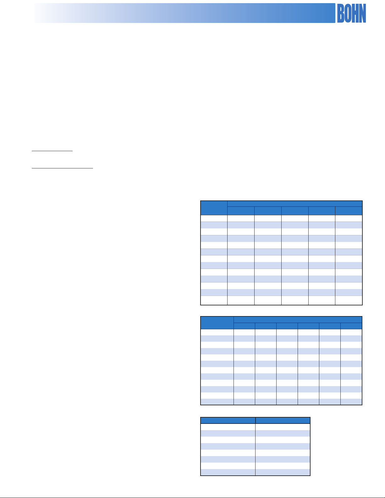
EC Sound Data (dBA @ 10 ft.)
Variable Speed Operation
The Venturi Mounted VSEC Series condensers provide variable
speed operation automatically; providing dramatically lower
sound and energy levels than would be observed with
condensers using traditional AC motors.
Typical performance of a Venturi Mounted VSEC Series
condenser at various loads versus a 540 RPM or 1140 RPM
condenser is shown in the charts on the next page.
Model Selection
Selecting the right Bohn VSEC Series unit for your needs
is easier than you think, and is just as easy as selecting a
standard unit.
Simply use Table 25 & 26 to nd the model and ns per inch
required to meet your capacity needs.
Selecting condensers with specic sound or energy levels
The variable speed nature allows selection to meet maximum
sound or energy usage levels.
To select condensers with these goals in mind, please contact
your sales representative. They will be able to help you select
the appropriate model for your specic requirements.
85
80
75
70
65
60
dBA @ 10 ft.
55
50
45
0 2 4 6 8 10 12 14
Number of Fans
22
BNE
Fans
1030
RPM
BNE
RPM
830
BNE
630
RPM
BNE
420
RPM
1 66.9 62.0 52.9 45.3
2 69.9 65.0 55.9 48.3
3 71.7 66.8 57.7 50.1
4 72.9 68.0 58.9 51.3
5 73.9 69.0 59.9 52.3
6 74.7 69.8 60.7 53.1
7 75.4 70.5 61.4 53.8
8 75.9 71.0 61.9 54.3
10 76.9 72.0 62.9 55.3
12 77.7 72.8 63.7 56.1
14 78.4 73.5 64.4 56.8
Page 23

Power Consumption & Variable Speed Operation
Bohn VSEC vs. 540 and 1140 Series
10 Fan EC Motor Sound Production at Various Loads
Percent of Max. Load 30% 40% 50% 60% 70% 80% 90% 100%
RPM 215 313 407 511 630 748 892 1030
dBA @ 10 ft 49.5 51.8 55 58.4 62.9 67.8 74.8 76.9
23
Page 24

CONDENSER CAPACITY
Table 19. BNJ Models, 830 RPM, 1.1 Kw, 30" Fan Diameter
BNJ 540 830 VSEC 1140
Model
R22/R410A
MBH / 1° TD
R404A / R507
MBH / 1° TD
8 FPI 10 FPI 12 FPI 14 FPI 8 FPI 10 FPI 12 FPI 14 FPI
BNJ-S01-A007 5.9 6.7 7.3 7.9 5.8 6.6 7.2 7.7
BNJ-S01-A008 7.2 8.0 8.6 9.0 7.0 7.8 8.4 8.8
BNJ-S02-A010 9.1 10.1 11.0 11.7 8.9 9.9 10.8 11.4
BNJ-S02-A014 12.6 13.9 14.9 15.7 12.4 13.6 14.6 15.4
BNJ-S02-A016 15.0 16.1 16.8 17.6 14.7 15.8 16.5 17.3
BNJ-S03-A021 18.9 20.9 22.3 23.4 18.6 20.5 21.8 23.0
BNJ-S03-A024 22.5 24.2 25.2 26.9 22.0 23.8 24.7 26.3
BNJ-S04-A028 25.3 27.8 29.7 31.2 24.8 27.3 29.1 30.6
BNJ-S04-A032 30.0 32.3 33.6 35.2 29.4 31.7 32.9 34.5
BNJ-S05-A035 32.1 35.5 37.4 39.0 31.4 34.7 36.6 38.2
BNJ-S05-A042 38.4 41.6 43.4 44.7 37.7 40.8 42.5 43.8
BNJ-S06-A050 46.1 49.9 52.1 53.6 45.2 48.9 51.0 52.6
BNJ-S07-A055 50.5 55.0 58.0 60.2 49.5 53.9 56.8 59.0
BNJ-D04-A020 18.1 20.2 22.0 23.3 17.7 19.8 21.5 22.9
BNJ-D04-A028 25.3 27.8 29.7 31.4 24.8 27.3 29.1 30.7
BNJ-D04-A032 30.0 32.3 33.6 35.2 29.4 31.7 32.9 34.5
BNJ-D06-A042 37.9 41.8 44.5 46.9 37.2 40.9 43.7 45.9
BNJ-D06-A048 45.0 48.4 50.4 53.7 44.1 47.5 49.4 52.7
BNJ-D08-A056 50.6 55.7 59.4 62.4 49.6 54.6 58.3 61.1
BNJ-D08-A065 60.0 64.6 67.2 70.4 58.8 63.3 65.8 69.0
BNJ-D10-A071 64.2 70.9 74.7 78.0 62.9 69.5 73.2 76.5
BNJ-D10-A083 76.9 83.1 86.8 89.4 75.3 81.5 85.0 87.6
BNJ-D12-A100 90.4 99.8 104.1 107.3 92.2 97.8 102.0 105.1
BNJ-D14-A110 101.1 110.0 116.0 120.3 99.1 107.9 113.7 117.9
BOLD indicates standard model capacity.
* Data based on mid point condensing temperature
24
Page 25

CONDENSER CAPACITY
Table 20. BNJ Models, 830 RPM, 1.1 Kw, 30" Fan Diameter
BNJ 540 830 VSEC 1140
Model
R407A / R407F*
MBH / 1° TD
R407C*
MBH / 1° TD
8 FPI 10 FPI 12 FPI 14 FPI 8 FPI 10 FPI 12 FPI 14 FPI
BNJ-S01-A007 5.7 6.5 7.0 7.6 5.5 6.2 6.8 7.2
BNJ-S01-A008 6.9 7.7 8.2 8.6 6.6 7.3 7.9 8.3
BNJ-S02-A010 8.7 9.7 10.6 11.2 8.3 9.3 10.1 10.8
BNJ-S02-A014 12.1 13.4 14.3 15.1 11.6 12.8 13.7 14.4
BNJ-S02-A016 14.4 15.5 16.1 16.9 13.8 14.9 15.5 16.2
BNJ-S03-A021 18.2 20.1 21.4 22.5 17.5 19.2 20.5 21.6
BNJ-S03-A024 21.6 23.3 24.2 25.8 20.7 22.3 23.2 24.8
BNJ-S04-A028 24.3 26.7 28.5 30.0 23.3 25.6 27.4 28.7
BNJ-S04-A032 28.8 31.0 32.3 33.8 27.6 29.8 31.0 32.4
BNJ-S05-A035 30.8 34.0 35.9 37.5 29.6 32.7 34.4 35.9
BNJ-S05-A042 36.9 39.9 41.7 42.9 35.4 38.3 40.0 41.2
BNJ-S06-A050 44.3 47.9 50.0 51.5 42.5 45.9 48.0 49.4
BNJ-S07-A055 48.5 52.8 55.7 57.8 46.6 50.7 53.4 55.4
BNJ-D04-A020 17.4 19.4 21.1 22.4 16.7 18.6 20.2 21.5
BNJ-D04-A028 24.3 26.7 28.5 30.1 23.3 25.6 27.4 28.9
BNJ-D04-A032 28.8 31.0 32.3 33.8 27.6 29.8 30.9 32.4
BNJ-D06-A042 36.4 40.1 42.8 45.0 34.9 38.5 41.0 43.2
BNJ-D06-A048 43.2 46.5 48.4 51.6 41.4 44.6 46.4 49.5
BNJ-D08-A056 48.6 53.5 57.1 59.9 46.6 51.3 54.8 57.5
BNJ-D08-A065 57.6 62.1 64.5 67.6 55.3 59.5 61.9 64.8
BNJ-D10-A071 61.6 68.1 71.8 74.9 59.1 65.3 68.9 71.9
BNJ-D10-A083 73.8 79.8 83.3 85.8 70.8 76.6 79.9 82.3
BNJ-D12-A100 90.4 95.8 99.9 103.0 86.7 91.9 95.9 98.8
BNJ-D14-A110 97.1 105.7 111.4 115.6 93.1 101.4 106.9 110.9
BOLD indicates standard model capacity.
* Data based on mid point condensing temperature
25
Page 26

BNJ 504 830 VSEC 1140
CONDENSER SPECIFICATIONS
Table 21. BNJ Models, 1.1 kW, 30" Fan Diameter
Model
CFM
230/3/60 460/3/60
Unit kWConn.
(in)
Max.
No. of
Feeds
Approx.
Net. Wt.
(lbs)
FLA MCA MOPD FLA MCA MOPD
BNJ-S01-A007 8400.0 6.6 15.0 25.0 3.3 15.0 15.0 1.1 1 3/8 7 340
BNJ-S01-A008 8000.0 6.6 15.0 25.0 3.3 15.0 15.0 1.1 1 3/8 14 370
BNJ-S02-A010 17500.0 13.2 15.0 30.0 6.6 15.0 15.0 2.1 1 3/8 14 600
BNJ-S02-A014 16700.0 13.2 15.0 30.0 6.6 15.0 15.0 2.1 1 5/8 21 650
BNJ-S02-A016 16100.0 13.2 15.0 30.0 6.6 15.0 15.0 2.1 2 1/8 28 700
BNJ-S03-A021 25100.0 19.8 21.5 35.0 9.9 15.0 15.0 3.2 2 1/8 21 960
BNJ-S03-A024 24100.0 19.8 21.5 35.0 9.9 15.0 15.0 3.2 2 1/8 28 1030
BNJ-S04-A028 32800.0 26.4 28.1 45.0 13.2 15.0 20.0 4.2 2 1/8 21 1250
BNJ-S04-A032 31200.0 26.4 28.1 45.0 13.2 15.0 20.0 4.2 2 5/8 28 1350
BNJ-S05-A035 41000.0 33.0 34.7 50.0 16.5 20.0 25.0 5.2 2 5/8 21 1570
BNJ-S05-A042 39100.0 33.0 34.7 50.0 16.5 20.0 25.0 5.2 2 5/8 28 1700
BNJ-S06-A050 46900.0 39.6 41.3 50.0 19.8 20.6 25.0 6.3 2 5/8 28 2020
BNJ-S07-A055 54700.0 46.2 47.9 60.0 23.1 23.9 30.0 7.3 2 @ 2 5/8 28 2320
BNJ-D04-A020 35000.0 26.4 28.1 45.0 13.2 15.0 20.0 4.2 2 @ 1 3/8 28 1280
BNJ-D04-A028 33500.0 26.4 28.1 45.0 13.2 15.0 20.0 4.2 2 @ 1 5/8 42 1380
BNJ-D04-A032 32100.0 26.4 28.1 45.0 13.2 15.0 20.0 4.2 2 @ 2 1/8 56 1480
BNJ-D06-A042 50200.0 39.6 41.3 50.0 19.8 20.6 25.0 6.3 2 @ 2 1/8 42 2060
BNJ-D06-A048 48200.0 39.6 41.3 50.0 19.8 20.6 25.0 6.3 2 @ 2 1/8 56 2210
BNJ-D08-A056 65600.0 52.8 54.5 70.0 26.4 27.2 35.0 8.4 2 @ 2 1/8 42 2720
BNJ-D08-A065 62500.0 52.8 54.5 70.0 26.4 27.2 35.0 8.4 2 @ 2 5/8 56 2920
BNJ-D10-A071 82000.0 66.0 67.7 80.0 33.0 33.8 40.0 10.4 2 @ 2 5/8 42 3400
BNJ-D10-A083 78100.0 66.0 67.7 80.0 33.0 33.8 40.0 10.4 2 @ 2 5/8 56 3650
BNJ-D12-A100 93700.0 79.2 80.9 90.0 39.6 40.4 45.0 12.5 2 @ 2 5/8 56 4360
BNJ-D14-A110 109300.0 92.4 94.1 110.0 46.2 47.0 50.0 14.6 4 @ 2 5/8 56 5060
26
Page 27

BNK 504 830 VSEC 1140
CONDENSER CAPACITY
Table 22. BNK Models, 1140 RPM, 2.0 kW, 30" Fan Diameter
Model
R22/R410A
MBH / 1° TD
R404A / R507
MBH/ 1° TD
8 FPI 10 FPI 12 FPI 14 FPI 8 FPI 10 FPI 12 FPI 14 FPI
BNK-S01-A007 6.4 7.3 8.0 8.6 6.3 7.2 7.9 8.5
BNK-S01-A009 7.8 8.7 9.5 10.0 7.6 8.6 9.3 9.8
BNK-S02-A011 9.6 10.7 11.7 12.4 9.4 10.5 11.5 12.1
BNK-S02-A015 13.1 14.5 15.6 16.3 12.8 14.2 15.3 16.0
BNK-S02-A017 15.7 17.1 18.1 19.2 15.3 16.7 17.7 18.8
BNK-S03-A022 19.7 21.8 23.4 24.5 19.3 21.4 22.9 24.0
BNK-S03-A026 23.5 25.7 27.1 29.9 23.0 25.1 26.6 29.3
BNK-S04-A029 26.2 29.1 31.2 32.6 25.7 28.5 30.5 32.0
BNK-S04-A034 31.4 34.2 36.1 38.3 30.7 33.5 35.4 37.6
BNK-S05-A037 33.6 37.1 39.3 41.3 32.9 36.4 38.5 40.5
BNK-S05-A044 40.5 44.0 46.0 48.6 39.7 43.1 45.1 47.6
BNK-S06-A053 48.6 52.8 55.2 58.3 47.7 51.7 54.1 57.1
BNK-S07-A061 55.4 61.0 64.7 67.5 54.3 59.8 63.5 66.2
BNK-D04-A021 19.2 21.4 23.4 24.8 18.8 21.0 22.9 24.3
BNK-D04-A029 26.2 29.1 31.2 32.6 25.7 28.5 30.6 32.0
BNK-D04-A034 31.4 34.2 36.1 38.3 30.7 33.5 35.4 37.6
BNK-D06-A044 39.4 43.6 46.7 48.9 38.6 42.8 45.8 47.9
BNK-D06-A051 47.0 51.3 54.2 59.8 46.1 50.3 53.1 58.7
BNK-D08-A058 52.5 58.2 62.3 65.3 51.4 57.0 61.1 63.9
BNK-D08-A068 62.7 68.4 72.3 76.7 61.5 67.1 70.8 75.1
BNK-D10-A074 67.1 74.2 78.5 82.6 65.7 72.7 76.9 80.9
BNK-D10-A088 81.0 88.0 92.1 97.2 79.4 86.2 90.2 95.2
BNK-D12-A106 97.2 105.6 110.5 116.6 95.3 103.5 108.3 114.2
BNK-D14-A122 110.8 121.9 129.5 135.0 108.6 119.5 126.9 132.4
BOLD indicates standard model capacity.
* Data based on mid point condensing temperature
27
Page 28

CONDENSER CAPACITY
Table 23. BNK Models, 1140 RPM, 2.0 Kw, 30" Fan Diameter
BNK 504 830 VSEC 1140
Model
R407A/407F*
MBH / 1° TD
407C*
MBH/ 1° TD
8 FPI 10 FPI 12 FPI 14 FPI 8 FPI 10 FPI 12 FPI 14 FPI
BNK-S01-A007 6.1 7.0 7.7 8.3 5.9 6.7 7.4 8.0
BNK-S01-A009 7.5 8.4 9.1 9.6 7.2 8.1 8.7 9.2
BNK-S02-A011 9.2 10.3 11.2 11.9 8.8 9.9 10.8 11.4
BNK-S02-A015 12.6 14.0 15.0 15.7 12.1 13.4 14.4 15.0
BNK-S02-A017 15.0 16.4 17.4 18.4 14.4 15.7 16.6 17.6
BNK-S03-A022 18.9 21.0 22.4 23.5 18.1 20.1 21.5 22.5
BNK-S03-A026 22.6 24.6 26.0 28.8 21.7 23.6 25.0 27.6
BNK-S04-A029 25.2 28.0 29.9 31.3 24.1 26.8 28.7 30.1
BNK-S04-A034 30.1 32.9 34.7 36.8 28.9 31.5 33.3 35.3
BNK-S05-A037 32.2 35.6 37.7 39.7 30.9 34.2 36.2 38.0
BNK-S05-A044 38.9 42.3 44.2 46.7 37.3 40.5 42.4 44.8
BNK-S06-A053 46.7 50.7 53.1 56.0 44.8 48.6 50.9 53.7
BNK-S07-A061 53.2 58.6 62.2 64.9 51.1 56.2 59.7 62.2
BNK-D04-A021 18.4 20.5 22.4 23.8 17.7 19.7 21.5 22.8
BNK-D04-A029 25.2 28.0 29.9 31.3 24.1 26.8 28.7 30.1
BNK-D04-A034 30.1 32.9 34.7 36.8 28.9 31.5 33.3 35.3
BNK-D06-A044 37.8 41.9 44.9 47.0 36.3 40.2 43.1 45.1
BNK-D06-A051 45.2 49.3 52.0 57.5 43.3 47.3 49.9 55.2
BNK-D08-A058 50.4 55.9 59.9 62.7 48.3 53.6 57.4 60.1
BNK-D08-A068 60.2 65.7 69.4 73.6 57.8 63.0 66.6 70.6
BNK-D10-A074 64.4 71.2 75.4 79.3 61.8 68.3 72.3 76.0
BNK-D10-A088 77.8 84.5 88.4 93.3 74.6 81.1 84.8 89.5
BNK-D12-A106 93.4 101.4 106.1 112.0 89.6 97.3 101.8 107.4
BNK-D14-A122 106.5 117.1 124.4 129.7 102.1 112.3 119.3 124.4
BOLD indicates standard model capacity.
* Data based on mid point condensing temperature
28
Page 29

BNK 504 830 VSEC 1140
CONDENSER SPECIFICATIONS
Table 24. BNK Models, 1140 RPM, 2.0 kW, 30" Fan Diameter
Model
CFM
230/3/60 460/3/60
Unit kWConn.
(in)
Max.
No. of
Feeds
Approx.
Net. Wt.
(lbs)
FLA MCA MOPD FLA MCA MOPD
BNK-S01-A007 9900.0 6.6 15.0 25.0 3.3 15.0 15.0 2.0 1 3/8 7 340
BNK-S01-A009 9500.0 6.6 15.0 25.0 3.3 15.0 15.0 2.0 1 3/8 14 370
BNK-S02-A011 20500.0 13.2 15.0 30.0 6.6 15.0 15.0 3.9 1 3/8 14 600
BNK-S02-A015 19800.0 13.2 15.0 30.0 6.6 15.0 15.0 3.9 1 5/8 21 650
BNK-S02-A017 19000.0 13.2 15.0 30.0 6.6 15.0 15.0 3.9 2 1/8 28 700
BNK-S03-A022 29700.0 19.8 21.5 35.0 9.9 15.0 15.0 5.9 2 1/8 21 960
BNK-S03-A026 28500.0 19.8 21.5 35.0 9.9 15.0 15.0 5.9 2 1/8 28 1030
BNK-S04-A029 38600.0 26.4 28.1 45.0 13.2 15.0 20.0 7.8 2 1/8 21 1250
BNK-S04-A034 37000.0 26.4 28.1 45.0 13.2 15.0 20.0 7.8 2 5/8 28 1350
BNK-S05-A037 48300.0 33.0 34.7 50.0 16.5 20.0 25.0 9.7 2 5/8 21 1570
BNK-S05-A044 46200.0 33.0 34.7 50.0 16.5 20.0 25.0 9.7 2 5/8 28 1700
BNK-S06-A053 55400.0 39.6 41.3 50.0 19.8 20.6 25.0 11.7 2 5/8 28 2020
BNK-S07-A061 64700.0 46.2 47.9 60.0 23.1 23.9 30.0 13.6 2 @ 2 5/8 28 2320
BNK-D04-A021 41000.0 26.4 28.1 45.0 13.2 15.0 20.0 7.8 2 @ 1 3/8 28 1280
BNK-D04-A029 39600.0 26.4 28.1 45.0 13.2 15.0 20.0 7.8 2 @ 1 5/8 42 1380
BNK-D04-A034 38100.0 26.4 28.1 45.0 13.2 15.0 20.0 7.8 2 @ 2 1/8 56 1480
BNK-D06-A044 59400.0 39.6 41.3 50.0 19.8 20.6 25.0 11.7 2 @ 2 1/8 42 2060
BNK-D06-A051 57100.0 39.6 41.3 50.0 19.8 20.6 25.0 11.7 2 @ 2 1/8 56 2210
BNK-D08-A058 77200.0 52.8 54.5 70.0 26.4 27.2 35.0 15.5 2 @ 2 1/8 42 2720
BNK-D08-A068 73900.0 52.8 54.5 70.0 26.4 27.2 35.0 15.5 2 @ 2 5/8 56 2920
BNK-D10-A074 96500.0 66.0 67.7 80.0 33.0 33.8 40.0 19.4 2 @ 2 5/8 42 3400
BNK-D10-A088 92400.0 66.0 67.7 80.0 33.0 33.8 40.0 19.4 2 @ 2 5/8 56 3650
BNK-D12-A106 110900.0 79.2 80.9 90.0 39.6 40.4 45.0 23.3 2 @ 2 5/8 56 4360
BNK-D14-A122 129400.0 92.4 94.1 110.0 46.2 47.0 50.0 27.2 4 @ 2 5/8 56 5060
29
Page 30

CONDENSER CAPACITY
BNE 540 830 VSEC 1140
Table 25. BNE Models, 2.0 kW, 31.5" Fan Diameter
R22 / R-410A
Model
MBH / 1° TD
8 FPI 10 FPI 12 FPI 14 FPI 8 FPI 10 FPI 12 FPI 14 FPI
BNE-S01-A008 6.8 7.7 8.5 9.1 6.6 7.6 8.3 9.0
BNE-S01-A009 8.3 9.3 10.0 10.6 8.1 9.1 9.8 10.4
BNE-S02-A011 10.2 11.3 12.4 13.1 10.0 11.1 12.1 12.9
BNE-S02-A015 13.9 15.4 16.5 17.3 13.6 15.1 16.2 17.0
BNE-S02-A018 16.6 18.1 19.2 20.3 16.3 17.8 18.8 19.9
BNE-S03-A023 20.9 23.1 24.8 25.9 20.4 22.7 24.3 25.4
BNE-S03-A027 24.9 27.2 28.7 31.7 24.4 26.7 28.2 31.1
BNE-S04-A031 27.8 30.8 33.0 34.6 27.2 30.2 32.4 33.9
R404/R507
MBH / 1° TD
BNE-S04-A036 33.2 36.3 38.3 40.6 32.6 35.5 37.5 39.8
BNE-S05-A039 35.6 39.3 41.6 43.8 34.9 38.5 40.8 42.9
BNE-S05-A047 43.0 46.6 48.8 51.5 42.1 45.7 47.8 50.5
BNE-S06-A056 51.6 56.0 58.6 61.8 50.5 54.8 57.4 60.5
BNE-S07-A065 58.7 64.6 68.6 71.6 57.6 63.3 67.3 70.2
BNE-D04-A023 20.4 22.7 24.8 26.2 19.9 22.2 24.3 25.7
BNE-D04-A031 27.8 30.8 33.1 34.6 27.2 30.2 32.4 33.9
BNE-D04-A036 33.2 36.3 38.3 40.6 32.6 35.5 37.5 39.8
BNE-D06-A046 41.7 46.2 49.5 51.9 40.9 45.3 48.6 50.8
BNE-D06-A054 49.8 54.4 57.4 63.4 48.8 53.3 56.3 62.2
BNE-D08-A062 55.6 61.7 66.1 69.2 54.5 60.5 64.7 67.8
BNE-D08-A073 66.5 72.5 76.6 81.3 65.2 71.1 75.1 79.7
BNE-D10-A079 71.1 78.6 83.2 87.5 69.7 77.0 81.6 85.8
BNE-D10-A093 85.9 93.3 97.6 103.0 84.2 91.4 95.7 100.9
BNE-D12-A112 103.1 111.9 117.1 123.6 101.0 109.7 114.8 121.1
BNE-D14-A129 117.5 129.2 137.2 143.1 115.2 126.7 134.5 140.3
BOLD indicates standard model capacity.
30
Page 31

CONDENSER CAPACITY
BNE 540 830 VSEC 1140
Table 26. BNE Models, 2.0 kW, 31.5" Fan Diameter
R407A/R407F*
Model
MBH / 1° TD
8 FPI 10 FPI 12 FPI 14 FPI 8 FPI 10 FPI 12 FPI 14 FPI
BNE-S01-A008 6.5 7.4 8.2 8.8 6.2 7.1 7.8 8.4
BNE-S01-A009 7.9 8.9 9.6 10.2 7.6 8.5 9.2 9.7
BNE-S02-A011 9.8 10.9 11.9 12.6 9.4 10.4 11.4 12.1
BNE-S02-A015 13.3 14.8 15.9 16.6 12.8 14.2 15.2 15.9
BNE-S02-A018 15.9 17.4 18.4 19.5 15.3 16.7 17.6 18.7
BNE-S03-A023 20.0 22.2 23.8 24.9 19.2 21.3 22.8 23.9
BNE-S03-A027 23.9 26.1 27.6 30.5 23.0 25.1 26.5 29.2
BNE-S04-A031 26.7 29.6 31.7 33.2 25.6 28.4 30.4 31.9
R407C*
MBH / 1° TD
BNE-S04-A036 31.9 34.8 36.8 39.0 30.6 33.4 35.3 37.4
BNE-S05-A039 34.2 37.8 40.0 42.0 32.8 36.2 38.3 40.3
BNE-S05-A047 41.3 44.8 46.9 49.5 39.6 43.0 45.0 47.5
BNE-S06-A056 49.5 53.8 56.2 59.3 47.5 51.6 53.9 56.9
BNE-S07-A065 56.4 62.1 65.9 68.8 54.1 59.5 63.2 66.0
BNE-D04-A023 19.5 21.8 23.8 25.2 18.8 20.9 22.8 24.2
BNE-D04-A031 26.7 29.6 31.7 33.2 25.6 28.4 30.5 31.9
BNE-D04-A036 31.9 34.8 36.8 39.0 30.6 33.4 35.3 37.4
BNE-D06-A046 40.1 44.4 47.6 49.8 38.4 42.6 45.6 47.8
BNE-D06-A054 47.9 52.2 55.2 61.0 45.9 50.1 52.9 58.5
BNE-D08-A062 53.4 59.2 63.4 66.4 51.2 56.8 60.9 63.7
BNE-D08-A073 63.9 69.7 73.6 78.1 61.3 66.8 70.6 74.9
BNE-D10-A079 68.3 75.5 79.9 84.0 65.5 72.4 76.7 80.6
BNE-D10-A093 82.5 89.6 93.7 98.9 79.1 85.9 89.9 94.9
BNE-D12-A112 99.0 107.5 112.5 118.7 94.9 103.1 107.9 113.8
BNE-D14-A129 112.8 124.1 131.9 137.5 108.2 119.1 126.5 131.9
BOLD indicates standard model capacity.
31
Page 32

CONDENSER SPECIFICATIONS
Table 27. BNE Models, 2.0 kW, 31.5" Fan Diameter
BNE 540 830 VSEC 1140
208-230/3/60 460/3/60
Model CFM
FLA MCA MOPD FLA MCA MOPD
BNE-S01-A008 11,000 7.0 15.0 25 3.5 15.0 15 2.0 1 3/8 7 330
BNE-S01-A009 10,500 7.0 15.0 25 3.5 15.0 15 2.0 1 3/8 14 360
BNE-S02-A011 23,400 14.0 20.0 35 7.0 15.0 15 4.0 1 3/8 14 590
BNE-S02-A015 22,000 14.0 20.0 35 7.0 15.0 15 4.0 1 5/8 21 640
BNE-S02-A018 20,900 14.0 20.0 35 7.0 15.0 15 4.0 2 1/8 28 690
BNE-S03-A023 33,100 21.0 22.8 40 10.5 15.0 20 6.0 2 1/8 21 930
BNE-S03-A027 31,400 21.0 22.8 40 10.5 15.0 20 6.0 2 1/8 28 1,010
BNE-S04-A031 42,600 28.0 29.8 45 14.0 15.0 20 8.0 2 1/8 21 1,220
BNE-S04-A036 40,000 28.0 29.8 45 14.0 15.0 20 8.0 2 5/8 28 1,320
BNE-S05-A039 53,200 35.0 36.8 50 17.5 20.0 25 10.0 2 5/8 21 1,520
UnitkWConn.
(in.)
Max.
Number
of Feeds
Approx.
Net
Weight
(lbs)
BNE-S05-A047 50,000 35.0 36.8 50 17.5 20.0 25 10.0 2 5/8 28 1,650
BNE-S06-A056 60,000 42.0 43.8 60 21.0 21.9 30 12.0 2 5/8 28 1,960
BNE-S07-A065 70,000 49.0 50.8 70 24.5 25.4 35 14.0 2 @ 2 5/8 28 2,260
BNE-D04-A023 46,700 28.0 29.8 45 14.0 15.0 20 8.0 2 @ 1 3/8 28 1,290
BNE-D04-A031 44,100 28.0 29.8 45 14.0 15.0 20 8.0 2 @ 1 5/8 42 1,390
BNE-D04-A036 41,800 28.0 29.8 45 14.0 15.0 20 8.0 2 @ 2 1/8 56 1,490
BNE-D06-A046 66,100 42.0 43.8 60 21.0 21.9 30 12.0 2 @ 2 1/8 42 2,060
BNE-D06-A054 62,700 42.0 43.8 60 21.0 21.9 30 12.0 2 @ 2 1/8 56 2,210
BNE-D08-A062 85,100 56.0 57.8 70 28.0 28.9 35 16.0 2 @ 2 1/8 42 2,730
BNE-D08-A073 80,000 56.0 57.8 70 28.0 28.9 35 16.0 2 @ 2 5/8 56 2,930
BNE-D10-A079 106,400 70.0 71.8 90 35.0 35.9 45 20.0 2 @ 2 5/8 42 3,410
BNE-D10-A093 100,100 70.0 71.8 90 35.0 35.9 45 20.0 2 @ 2 5/8 56 3,660
BNE-D12-A112 120,100 84.0 85.8 100 42.0 42.9 50 24.0 2 @ 2 5/8 56 4,370
BNE-D14-A129 140,100 98.0 99.8 110 49.0 49.9 60 28.0 4 @ 2 5/8 56 5,070
32
Page 33

CONDENSER DIMENSIONS
End Views
Single Row of Fans
Double Row of Fans
Side Views
1 x 1
1 x 3
2 x 3
1 x 2
2 x 2
1 x 4
2 x 4
1 x 5
2 x 5
1 x 6
2 x 6
1 x 7
2 x 7
33
Page 34

Fan Cycle Control Panels
Fan cycling panels are available to cycle fans on ambient
temperature or condensing pressure or custom built control
panels can be factory installed to interface with electronic
refrigeration controllers.
• All fans are cycled with contactors.
• Condensers with a single row of fans cycle fans separately
with one contactor per fan.
• Condensers with two rows of fans cycle fans in pairs, with
one contactor for every pair of fans.
• Fans closest to the header end of the unit run continuously.
Ambient Fan Cycle
Condenser fans are controlled by ambient temperature
using electronic temperature controls. Ambient fan cycling is
recommended for multi-circuited condensers or single circuit
condensers where there is little variation in condenser load.
Ambient fan cycling is limited in its ability to control head pressure
to mild ambient conditions, see Table 28 for minimum ambients
for fan cycling. Full year head pressure control can be obtained
by combining ambient fan cycling with another means of head
Pressure Fan Cycling
• Standard control circuit voltage is 230 volts. Control
circuits with 24 or 115 volts are available on request.
• Control circuits are factory wired to a control circuit
terminal board for convenient single point eld wiring.
• Standard control circuits require an external power supply
for powering control circuit (by others).
• A control circuit transformer is available on 460 volt
condensers as a factory mounted option to provide
power to the control circuit.
pressure control, such as condenser ooding controls or variable
speed. Combining these controls with ambient fan cycling has the
additional advantage of reducing the amount of refrigerant required
to ood the condenser.
See Table 29 for typical settings for ambient thermostats.
Condenser fans are controlled by pressure switches which
monitor condenser pressure. Pressure fan cycling is ideal for
those condensers which see a signicant change in condenser
load. Since the controls sense condensing pressure, they can
cycle fans at any ambient temperature, in response to a change in
condensing pressure.
An additional pressure switch is available as an option to cycle the
fan closest to the header end of the condenser. This option is only
recommended for condensers with large variations in condenser
load caused by heat reclaim, hot gas defrost or a high percentage of
compressor unloading.
Table 28. Minimum Ambient for Fan Cycling
Number of Fans Design T.D.*
Single Row Double Row 30 25 20 15 10
2 4 35 45 55 60 70
3 6 15 30 40 55 65
4 8 0 15 30 45 60
5 10 0 10 20 35 55
6/7 12/14 0 0 10 30 50
*Based on maintaining 90° F minimum condensing temperature.
34
Page 35

Table 29. Fan Cycling Thermostat Settings
Number of Fans Design Thermostat Setting
Single Row Double Rows T.D. 1 2 3 4 5
2 4 30 60
25 65
20 70
15 75
10 80
3 6 30 60 40
25 65 55
20 70 60
15 75 65
10 80 75
4 8 30 60 50 30
25 65 55 40
20 70 65 50
15 75 70 60
10 80 75 70
5 10 30 60 55 45 30
25 65 60 50 35
20 70 65 60 40
15 75 70 65 55
10 80 75 70 65
6/7 12/14 30 55 50 40 30 25
25 65 60 55 45 35
20 70 65 60 50 40
15 75 70 65 60 50
10 80 75 70 65 60
Variable Speed
Condenser head pressure control is provided by varying the air ow through the condenser by changing the RPM of the condenser fan. This
control package is oered in combination with ambient fan cycling. The fan motor next to the header end of the condenser is the variable
speed fan. The remainder of the fans are constant speed and are cycled separately using ambient sensing thermostats. On condensers with
two rows of fans, two variable speed fans are provided (one per row) and the remainder of the fans are constant speed and are cycled in
pairs. The variable speed control package consists of a special variable speed motor (1140 RPM, single phase) and an electronic speed control
which controls the speed of the motor in response to condensing pressure. Fan motor, speed control and all related components are all
factory mounted and wired. Two speed controls are provided on units with two rows of fans to allow for separate control of each fan motor.
Splitting Controls
Additional head pressure can be provided by valving o a portion of the condenser circuit and removing that portion from the refrigeration
circuit, or splitting the condenser. In addition to providing a means of head pressure control, this control will reduce the amount of refrigerant
required to operate the condenser with a ooded head pressure control. Condenser splitting is recommended as a seasonal adjustment
controlled by ambient temperature. A pressure switch is also provided as a backup control to prevent high head pressures from occurring
during heavy load conditions. On condensers with a single row of fans the control package consists of an ambient sensing thermostat, a
pressure switch sensing condensing pressure and a splitting relay. The splitting relay provides a set of dry contacts to control the valves
required to split the condenser (valves supplied by others). On condensers with double rows of fans, additional controls and contactors are
provided to cycle all of the fans on the side of the condenser which has been split o. Except as noted above, the splitting packages do not
control fan cycling. It is recommended that fan cycling be controlled by combining the splitting package with pressure fan cycling.
Control Panels for Electronic Controllers
Custom control panels can often be fabricated to interface with many of the microprocessor based electronic refrigeration controls.
These panels often include individual motor fusing, individual fan motor contactors, splitting relays and printed circuit boards to
interface with the microprocessor control. Contact the factory with your specic requirements.
35
Page 36

Condenser Refrigerant Charge
The normal summer operating charge for condensers is shown
in Table 30. This charge can also be used in condensers with fan
cycling kits, since added refrigerant is not required for mild weather
control. Table 30 also contains the additional refrigerant charge
required when using ooded style head pressure controls.
Combining fan cycling with ooded head pressure controls
signicantly reduces the amount of winter charge required to ood
the condenser. Table 32 shows the refrigerant charge required
when fan cycling is used in conjunction with a ooded style head
pressure control.
Table 30. Refrigerant Charge, Lbs. R22 for Flooded Condenser
Refrigerant R22
Model*
1 8 7 10 11 11 11
2 10 10 13 15 15 16
3 10 10 13 14 15 15
4 15 15 19 21 22 23
5 20 19 26 29 30 31
6 22 22 29 32 34 35
7 30 29 38 42 44 46
8 51 50 66 74 77 80
9 70 66 87 96 100 105
10 64 62 83 92 95 99
11 86 83 110 122 127 132
12 102 100 132 147 153 159
13 118 117 155 172 179 186
14 19 20 27 29 31 32
15 29 30 39 44 46 47
16 40 39 51 57 59 62
17 44 44 58 64 67 70
18 58 59 78 86 90 94
19 104 99 131 146 152 158
20 140 131 174 193 201 209
21 125 126 168 186 194 201
22 172 165 219 243 253 263
23 201 201 267 296 308 320
24 236 233 310 343 357 372
Charge
for summer
Operation, Lbs.
+60 +40 +20 +0 -20
Additional Refrigerant R22 Charge Required
for Flooded Condenser Operation
Lbs. For 20°F TD
Minimum Ambient at Condenser
* See Model Cross Reference Table #33.
Table 31. Flooded Charge Temperature Dierence Factor
Design T.D.
Ambient, °F 30 25 20 15 10
+60 0.38 1.0 1.74 2.46
+40 0.59 0.80 1.0 1.19 1.40
+20 0.76 0.88 1.0 1.13 1.25
0 0.84 0.91 1.0 1.07 1.16
-20 0.88 0.93 1.0 1.05 1.13
----
36
Page 37

Table 32. Refrigerant Charge for Fan Cycling plus Flooded Condenser (lbs. R-22)
Model*
Summer
Charge
1 8 7 8 9 9 8 9 10 10 9 10 11 11 13 12 12 12
2 10 9 12 13 14 11 13 14 15 13 14 15 16 17 18 17 18
3 10 1 6 8 10 4 8 10 11 7 10 12 13 10 13 14 14
4 15 2 9 12 15 7 12 15 17 12 16 18 19 17 19 21 22
5 20 3 11 16 19 9 16 20 22 15 21 24 25 21 25 27 28
6 22 0 3 10 15 0 10 16 20 0 17 22 25 0 24 27 29
7 30 0 4 13 20 0 12 20 26 0 21 27 32 0 29 34 38
8 51 0 0 8 22 0 6 23 35 0 22 38 48 0 37 52 61
9 70 0 0 11 29 0 8 31 46 0 29 51 63 0 49 71 80
10 64 0 0 0 15 0 0 17 33 0 0 39 52 0 0 60 70
11 86 0 0 0 19 0 0 22 44 0 0 50 69 0 0 78 93
40°F 20°F 0°F -20°F 40°F 20°F 0°F -20°F 40°F 20°F 0°F -20°F 40°F 20°F 0°F -20°F
25° TD 20° TD 15° TD 10° TD
12 102 0 0 0 6 0 0 8 37 0 0 37 69 0 0 66 100
13 118 0 0 0 0 0 0 0 29 0 0 0 69 0 0 0 108
14 19 3 12 17 20 9 17 21 23 15 22 25 26 21 27 29 29
15 29 4 17 24 29 13 24 30 34 22 31 36 39 31 38 41 43
16 40 5 22 32 38 17 31 39 44 29 40 46 50 41 49 53 56
17 44 0 5 20 31 0 18 31 40 0 31 42 49 0 44 53 59
18 58 0 7 27 42 0 25 42 54 0 43 57 66 0 61 71 79
19 104 0 0 17 44 0 12 47 69 0 43 77 95 0 74 107 119
20 140 0 0 22 57 0 16 62 91 0 57 102 125 0 99 141 157
21 125 0 0 0 30 0 0 34 67 0 0 77 105 0 0 120 141
22 172 0 0 0 39 0 0 44 88 0 0 100 137 0 0 156 186
23 201 0 0 0 11 0 0 16 74 0 0 74 137 0 0 132 200
24 236 0 0 0 0 0 0 0 57 0 0 0 135 0 0 0 213
* See Model Cross Reference Table #33.
Refrigerant Multiply charge by:
R-134a 0.99
R-404A 0.91
R-407A 0.96
Note: For other refrigerants, use the table at the right. For alternate T.D.s, multiply by
flooded charge T.D. factors in Table 31.
Refrigerant Multiply charge by:
R-407C 0.95
R-410A 0.96
R-507A 0.91
37
Page 38

Table 33. Model Cross Reference
Model
Reference
1 BNH-S01-A007 BNK-S01-A007 BNL-S01-A007 BNJ-S01-A007 BNX-S01-A006 BNQ-S01-A005 BNE-S01-A008
2 BNH-S01-A009 BNK-S01-A009 BNL-S01-A008 BNJ-S01-A008 BNX-S01-A008 BNQ-S01-A006 BNE-S01-A009
3 BNH-S02-A011 BNK-S02-A011 BNL-S02-A010 BNJ-S02-A010 BNX-S02-A010 BNQ-S02-A008 BNE-S02-A011
4 BNH-S02-A015 BNK-S02-A015 BNL-S02-A014 BNJ-S02-A014 BNX-S02-A013 BNQ-S02-A010 BNE-S02-A015
5 BNH-S02-A017 BNK-S02-A017 BNL-S02-A016 BNJ-S02-A016 BNX-S02-A015 BNQ-S02-A011 BNE-S02-A018
6 BNH-S03-A022 BNK-S03-A022 BNL-S03-A021 BNJ-S03-A021 BNX-S03-A020 BNQ-S02-A016 BNE-S03-A023
7 BNH-S03-A026 BNK-S03-A026 BNL-S03-A024 BNJ-S03-A024 BNX-S03-A023 BNQ-S03-A017 BNE-S03-A027
8 BNH-S04-A029 BNK-S04-A029 BNL-S04-A028 BNJ-S04-A028 BNX-S04-A026 BNQ-S04-A021 BNE-S04-A031
9 BNH-S04-A034 BNK-S04-A034 BNL-S04-A032 BNJ-S04-A032 BNX-S04-A030 BNQ-S04-A023 BNE-S04-A036
10 BNH-S05-A037 BNK-S05-A037 BNL-S05-A035 BNJ-S05-A035 BNX-S05-A033 BNQ-S05-A026 BNE-S05-A039
11 BNH-S05-A044 BNK-S05-A044 BNL-S05-A042 BNJ-S05-A042 BNX-S05-A038 BNQ-S05-A029 BNE-S05-A047
12 BNH-S06-A053 BNK-S06-A053 BNL-S06-A050 BNJ-S06-A050 BNX-S06-A045 BNQ-S06-A034 BNE-S06-A056
13 BNH-S07-A061 BNK-S07-A061 BNL-S07-A055 BNJ-S07-A055 BNX-S07-A052 BNQ-S07-A042 BNE-S07-A065
14 BNH-D04-A021 BNK-D04-A021 BNL-D04-A020 BNJ-D04-A020 BNX-D04-A020 BNQ-D04-A016 BNE-D04-A023
15 BNH-D04-A029 BNK-D04-A029 BNL-D04-A028 BNJ-D04-A028 BNX-D04-A026 BNQ-D04-A021 BNE-D04-A031
16 BNH-D04-A034 BNK-D04-A034 BNL-D04-A032 BNJ-D04-A032 BNX-D04-A030 BNQ-D04-A023 BNE-D04-A036
17 BNH-D06-A044 BNK-D06-A044 BNL-D06-A042 BNJ-D06-A042 BNX-D06-A039 BNQ-D06-A031 BNE-D06-A046
18 BNH-D06-A051 BNK-D06-A051 BNL-D06-A048 BNJ-D06-A048 BNX-D06-A045 BNQ-D06-A034 BNE-D06-A054
19 BNH-D08-A058 BNK-D08-A058 BNL-D08-A056 BNJ-D08-A056 BNX-D08-A052 BNQ-D08-A041 BNE-D08-A062
20 BNH-D08-A068 BNK-D08-A068 BNL-D08-A065 BNJ-D08-A065 BNX-D08-A061 BNQ-D08-A046 BNE-D08-A073
21 BNH-D10-A074 BNK-D10-A074 BNL-D10-A071 BNJ-D10-A071 BNX-D10-A066 BNQ-D10-A052 BNE-D10-A079
22 BNH-D10-A088 BNK-D10-A088 BNL-D10-A083 BNJ-D10-A083 BNX-D10-A076 BNQ-D10-A057 BNE-D10-A093
23 BNH-D12-A106 BNK-D12-A106 BNL-D12-A100 BNJ-D12-A100 BNX-D12-A091 BNQ-D12-A069 BNE-D12-A112
24 BNH-D14-A122 BNK-D14-A122 BNL-D14-A110 BNJ-D14-A110 BNX-D14-A104 BNQ-D14-A083 BNE-D14-A129
BNH BNK BNL BNJ BNX BNQ BNE
Calculate Refrigerant Charge
Refrigeration operating charges are located in Table 30 for ooded condenser and Table 32 for fan cycling plus ooded condenser.
Charge for ooded condenser = summer charge (Table 30) + additional ooding charge (Table 30) * ooded charge T.D. factor (Table 31)
Charge for fan cycling + ooding = summer charge (Table 32) + additional charge for fan cycling (Table 32)
Example:
Obtain the summer charge for a BNH-S05-A037. What is the ooding charge required to operate this condenser at 0° ambient at a 20°T.D. with
R-22 refrigerant? What is the reduction in operating charge if fan cycling is combined with ooding?
Procedure:
From Table 33, obtain the model reference for BNH-S05-A037 as model 10. From Table 30, obtain the summer operating charge for model 10
at 64 lbs. The charge for winter operation with ooded controls is equal to the summer operating charge of 64 lbs. plus the additional charge
at 0° ambient (Table 30) of 95 lbs., times the ooded charge T.D. factor (Table 31) of 1.0 for 20°T.D.
Charge for ooded condenser = 64 + (95) * 1.0
= 159 lbs.
The charge for fan cycling plus ooded condenser is obtained using Table 32. Using this table obtain the additional charge for 20°T.D. at 0°
ambient, which is 17 lbs. The total charge is the summer charge (64 lbs.) plus the additional charge.
Charge for fan cycle + ooding = 64 + 17
= 81 lbs.
The savings in refrigerant charge = 159 - 81
= 78 lbs.
38
Page 39

Diagram 1. Typical Condenser Wiring Diagram With No Fan Cycle Controls
39
Page 40

Diagram 2. Typical Condenser Wiring Diagram With Fan Cycle Controls
40
Page 41

Sound Data for 3-Phase A/C , 1140 Series and Rail Mounted VSEC
21
Unit Sound Data (dBA @ 10 ft.)
BNH/BNK
BNH BNL BNX BNQ
85.0
80.0
75.0
70.0
65.0
dBA @ 10 ft.
60.0
55.0
50.0
45.0
02468101
BNH/BNK
BNH/BNK
BNL/BNJ
BNX
BNQ
Number of Fans
4
Unit Sound Data (dBA @ 10 ft.)
Fans BNH/BNK BNL/BNJ BNX BNQ
1 72.3 63.4 60.8 49.6
2 75.3 66.4 63.8 52.6
3 77.1 68.1 65.6 54.4
4 78.3 69.4 66.8 55.6
5 79.3 70.3 67.8 56.6
6 80.1 71.1 68.6 57.4
7 80.8 71.8 69.3 58.1
8 81.3 72.4 69.8 58.6
10 82.3 73.4 70.8 59.6
12 83.1 74.1 71.6 60.4
14 83.8 74.8 72.3 61.1
41
Page 42

Notes43Notes
42
Page 43

Page 44

44
A Brand of Heatcraft Refrigeration Products, LLC
2175 West Park Place Blvd. • Stone Mountain, GA • 30087
(800) 537.7775 • heatcraftrpd.com
Visit our website at www.heatcraftrpd.com for technical literature online.
Since product improvement is a continuing effort, we reserve the right to
make changes in specifications without notice.
 Loading...