


C 10 L
Table of contents
 Loading...
Operating instructions
Directly coupled
screw compressors
Series
C 10 L...C 20 L
Separate manual:
Compressor control
www.boge.com


Operating instructions
for directly coupled
screw compressors
– C 10 L (10.0 Hp)
– C 15 L (15.0 Hp)
– C 20 L (20.0 Hp)
BOGE KOMPRESSOREN
Postfach 10 07 13
33507 Bielefeld
Germany
Otto-Boge-Straße 1-7
33739 Bielefeld
Phone: +49 5206 601-0
Fax: +49 5206 601-200
Mail: info@boge.com
Net: www.boge.com
Issue: 12 / 2011
No. 596.1191.18
Nominal price: € 5,00
BOGE Operating instructions for C 10 L...C 20 L series screw compressors Page I


Index
Index
Part 1:
General
Part 2:
Product description
1.1 General safety instructions ........................................................... 1
Safety instructions for compressor operation ................................... 1
Safety instructions for maintenance and repair of the compressor... 2
Accident prevention regulations........................................................ 2
1.2 Introduction..................................................................................... 3
Symbols used ................................................................................... 4
Intended use ..................................................................................... 7
Foreseeable misuse ......................................................................... 7
Transport damage ............................................................................ 8
Data on the type plate....................................................................... 8
Service.............................................................................................. 8
2.1 Technical data................................................................................. 9
2.2 Function description .................................................................... 10
Function principle of the air end...................................................... 10
Air circuit ......................................................................................... 11
Oil circuit ......................................................................................... 12
2.3 Compressor control ..................................................................... 13
Network pressure............................................................................ 13
Operating states ............................................................................. 13
Operating modes ............................................................................ 13
Short operating times...................................................................... 14
2.4 Control devices............................................................................. 14
Operating pressure sensor ............................................................. 14
2.5 Safety and monitoring devices.................................................... 14
General ........................................................................................... 14
Safety valve .................................................................................... 15
Safety temperature limiting device.................................................. 15
Monitoring the drive motor .............................................................. 15
Part 3:
Installation
BOGE Operating instructions for C 10 L...C 20 L series screw compressors Page III
3.1 Transport and storage.................................................................. 17
General ........................................................................................... 17
Transport possibilities ..................................................................... 17
Intermediate storage....................................................................... 18

Index
3.2 Compressor room......................................................................... 19
Installation, maintenance conditions and application for com-
pressed air receivers arranged below or separately ....................... 19
Installation surface.......................................................................... 19
Fire protection................................................................................. 19
Sound protection............................................................................. 20
Admissible environmental influences.............................................. 20
Ventilation ....................................................................................... 20
Cooling air requirement .................................................................. 21
Condensate disposal ...................................................................... 21
3.3 Installation..................................................................................... 22
General ........................................................................................... 22
Checking the delivery scope........................................................... 22
Installing the compressor................................................................ 22
Connecting the compressor to the compressed air network........... 23
Checking the oil level...................................................................... 23
Part 4:
Faults
Part 5:
Maintenance
3.4 Electrical connection.................................................................... 23
3.5 Commissioning............................................................................. 24
Check installation requirements...................................................... 24
Checking the rotational direction .................................................... 25
Check compressed air outlet for tightness...................................... 25
Opening the stop valves ................................................................. 26
Checking for leaks .......................................................................... 26
Conduct trial run ............................................................................. 26
Commissioning following extended stoppages............................... 26
Refrigeration compressed air dryer ................................................ 27
3.6 Dismantling ................................................................................... 28
4.1 General .......................................................................................... 29
4.2 General faults................................................................................ 29
5.1 Safety instructions ....................................................................... 31
5.2 General .......................................................................................... 32
Maintenance through BOGE service .............................................. 32
Review of regular maintenance work.............................................. 32
Maintenance intervals..................................................................... 33
General information concerning the lubricants used ...................... 35
Disposal of used operating material ............................................... 36
Pressure hoses............................................................................... 36
Spare and wearing parts................................................................. 36
Page IV BOGE Operating instructions for C 10 L...C 20 L series screw compressors

Index
5.3 Regular maintenance work .......................................................... 37
Clean or change suction filter ......................................................... 37
Cleaning the filter cartridge............................................................. 37
Drive motors with permanent lubrication ........................................ 38
Checking the oil level, topping up oil .............................................. 38
Changing the oil filter ...................................................................... 39
Changing the oil separator.............................................................. 40
Oil change....................................................................................... 42
Flushing the oil circuit ..................................................................... 44
Cleaning the compressed air/oil cooling unit .................................. 44
Checking the safety valve............................................................... 45
Nozzle with dirt catch...................................................................... 45
5.4 Spare parts and optional equipment .......................................... 47
List of spare and wearing parts (for maintenance) ......................... 47
List of available optional equipment................................................ 47
Part 6:
Appendix
6.1 Flow chart...................................................................................... 49
Air cooled version, standard ........................................................... 50
6.2 List of maintenance and service work........................................ 52
BOGE Operating instructions for C 10 L...C 20 L series screw compressors Page V


General 1.1 General safety instructions
Part 1: General 1.1 General safety instructions
WARNING!
Nonobservance of the following safety instructions may lead to injuries and
damage to the compressor.
Also observe the generally valid safety and accident prevention regulations
in addition to the information in these operating instructions!
Safety instructions for compressor operation
1. Ensure that no commissioning and maintenance work on the compressor
is undertaken until these operating instructions are understood.
2. Only use the compressor for its intended use, as described in these operating instructions.
3. The owner must ensure:
– that only appropriately trained and authorized personnel work on this
compressor,
– that the operating, maintenance and repair personnel has been made
fully familiar with all safety instructions, and that they are being
observed,
– that the compressor is only operated in a safe operating condition.
4. Avoid any operating method which may impair the safety of the compressor.
5. Do not exceed the limit value for the final compression pressure specified
on the type plate.
6. Do not operate the compressor without the attendant protection and safety
devices.
Do not dismantle any built-in safety devices or put them out of operation.
Ensure that all safety claddings and doors are closed prior to commissioning/starting up the compressor and that they are not opened during operation.
7. Place the compressor out of operation as described in these operating
instructions, when dismantling the safety claddings or safety devices for
repair or maintenance work. Reattach and close all cladding and safety
devices immediately upon completion of the repair or maintenance work.
8. Only operate the compressor using the additional equipment (options) recommended or authorized by the manufacturer.
9. Undertake conversions and modifications of the compressor only in agreement with BOGE, taking all relevant safety regulations into consideration.
The manufacturer is not liable for damages resulting from independent
modifications on the compressor.
10. Never start the compressor when one or serveral parts (e.g. cable, plug)
are damaged, when not in perfect working order and when damage is
detected or suspected.
11. Observe all safety and danger signs directly attached on the compressor!
BOGE Operating instructions for C 10 L...C 20 L series screw compressors Page 1
General 1.1 General safety instructions
Safety instructions for maintenance and repair of the compressor
Caution!
Only use original spare parts, compressor oils and operating materials released by BOGE during repair or maintenance!
Attention: High voltage!
When working on the electrical system there is a constant danger of getting
into contact with live parts!
To avoid such dangers the mains connection must be equipped with a disconnecting device!
1. Ensure that maintenance work is only carried out by appropriately trained
persons.
2. Ensure that setting work, malfunction rectification and repair is only carried
out by specialists or appropriately trained persons.
3. Prior to maintenance or repair work:
– Switch off the main switch.
– Secure main switch against unintentional switch-on.
– Check to ensure that all parts are currentless.
– Disconnect the compressor from the compressed air network (relieve
or block pressurized lines).
4. Exercise extreme caution during repair or maintenance work requiring the
compressor to be operational.
Ensure that persons keep out of reach of the hazardous area.
5. Ensure that work on the electrical equipment is only executed by qualified
electricians.
6. Work on parts and devices under current is prohibited. Exceptions are
governed by the appropriate regulations.
7. The operator is responsible to check the compressor daily for externally
visible damage and defects, and to immediately report any changes
(including operational behaviour).
8. When the automatic restart (Auto-Restart) is activated, the compressor will
start automatically following a voltage loss.
Prerequisite: The net pressure is lower than the set switch-on pressure.
Accident prevention regulations
Page 2 BOGE Operating instructions for C 10 L...C 20 L series screw compressors
The owner of a compressor plant is required to ensure that it is properly installed, operated and maintained.
For operation of the compressor plant, the accident prevention regulations of
the owner country must be observed in addition to the data contained in these
operating instructions.

General 1.2 Introduction
In the event that measures are required above and beyond the legal regulations or the data contained in these operating instructions, then it is of utmost
importance that these be carried out prior to commissioning the compressor
plant.
WARNING!
Failure to adhere to these recommendations can result in mechanical failure,
property damange and serious injury or death.
All air and water inlet as well as air and water discharge pipework to and from
the inlet and discharge port connections must be designed in such a way as
to take into account vibration, pulsations, temperature, maximum pressure
applied, corrosion and chemical resistance. In addition, it should be noted
that lubricated compressors will discharge some oil into the air stream; there
fore, compatibility between discharge piping, system accessories and software must be assured.
For those reasons, the use of plastic piping and soldered copper fittings as
discharge piping is not recommended. In addition, flexible joints and/or flex
lines can only be considered for such purposes if their specifications fit the
operating parameters of the system.
It is the responsibility of the installer and owner to provide the appropriate
service pipework to and from the machine.
-
WARNING!
Statement concerning inadvertent breathing of compressed air
exhaust.
The purchaser/user must ensure that adequate ventilation and make-up air
are provided if a non-BAP designated compressor is likely to discharge air
into a confined area harboring air consuming devices such as air motors, air
tools, solenoids, air cylinders, air guns, nozzles, etc. The compressed air dis
charge stream may contain residual coolants/lubricants/carbon monoxide
and condensable hydrocarbons or other materials which may be hazardous
to health with prolonged inhalation.
-
1.2 Introduction
The purpose of these operating instructions is to familiarize the user with the
function and all application possibilities of the compressor.
These operating instructions contain important information on how to operate
the compressor safely, economically and according to its intented use. Ob
serving these operating instructions will assist in avoiding danger, to reduce
repair costs and down times and to increase the reliability and service life of
the compressor. It contains important information concerning the required
maintenance and repair measures, assists in case of malfunctions and con
tains data concerning spare and wearing parts.
-
-
BOGE Operating instructions for C 10 L...C 20 L series screw compressors Page 3
General 1.2 Introduction
The operating instructions must be available to the compressor operating personnel at the place of operation, at all times.
The operating instructions must be carefully read and applied by all persons
engaged to undertake the following work on the compressor:
– Operation, including fault rectification and daily care
– Maintenance (service, inspection, repair)
– Commissioning
– Transport
The compressor and its additional equipment must not be installed and commissioned until the operating instructions are understood.
These operating instructions can be supplemented with instructions on the
basis of existing national regulations concerning accident prevention and envi
ronmental protection.
In the illustrations, the compressor is shown in part without safety cladding or
safety devices for better visualization. However, operation without these com
ponents is prohibited!
-
-
Symbols used
In these operating instructions, important safety instructions and tips are identified by the following symbols:
DANGER: Risk of injury!
This symbol indicates information warning of possible danger to life and limb
of the operator or other persons.
CAUTION!
This symbol indicates information warning of dangers to life and limb of the
operator or other persons or dangers, which might destroy or damage the
compressor.
DANGER: Voltage!
This symbol indicates information warning of life threatening electrical voltage levels.
It indicates work which must be exclusively performed by skilled electricians.
NOTICE!
This symbol indicates information and tips concerning the economical and
careful operation of the compressor.
Page 4 BOGE Operating instructions for C 10 L...C 20 L series screw compressors
General 1.2 Introduction
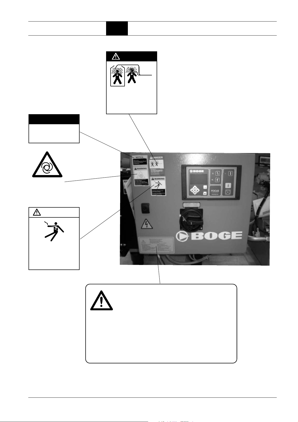
DANGER
Discharge air.
Can contain carbon monoxide
or other contaminants. Will
cause severe injury or death.
Do not breathe this air.
NOTICE
Refer to the
Instruction/ Operators Manual
before performing any
maintenance.
Warning:
The unit is operated by
remote control, and might
start without warning.
WARNING
Hazardous voltage. Can cause
severe injury or death.
Disconnect power before
servicing.
Lockout/Tagout machine.
Before working at the compressor:
– disconnect all current-carrying parts!
– check if all parts are actually voltage-free!
– secure the compressor against switching-on!
– reduce the pressure in all areas!
If you neglect these rules, your health will be endangered!
Before putting into service:
– read the instructions
– check electric connections
– check oil-level (not for oil-free)
– if applicable, remove the transportation safety
device
– check the direction of rotation of compressor
– operate only with a belt protective grating
or a sound protection bonnet.
– do not close the cooling air inlets and outlets
during operation!
Regular maintenance:
Observe the operating instructions!
– check suction filter weekly, if necessary clean
or replace it
– check cooler for dirt, if necessary clean it
– check oil-level weekly (not for oil-free)
– drain condensation water from pressure tank
at least once a week
– check operativeness of automatic steam trap
BOGE Operating instructions for C 10 L...C 20 L series screw compressors Page 5

General 1.2 Introduction
WARNING
Hot surface.
Can cause severe injury.
Do not touch. Allow to cool before
servicing.
WARNING
High pressure air.
Can cause severe injury or death.
Relieve pressure before removing
filter plugs / caps, fittings or covers.
WARNING
WARNING
Exposed fan blade.
Can cause severe injury.
Do not operate with covers
removed. Disconnect power.
Lock and tag.
NOTICE
Rotation.
High pressure air.
Can cause severe injury or death.
Relieve pressure before removing
filter plugs / caps, fittings or covers.
WARNING
Hot surface.
Can cause severe injury.
Do not touch. Allow to cool before
servicing.
NOTICE
Lift here.
WARNING
Hot surface.
Can cause severe injury.
Do not touch. Allow to cool before
servicing.
NOTICE
Rotation.
Page 6 BOGE Operating instructions for C 10 L...C 20 L series screw compressors
General 1.2 Introduction
Intended use
BOGE compressors, including their additional equipment, are exclusively intended for the compression of air.
The air taken in must not contain any explosive or chemically instable gases
or vapours.
Do not exceed the specified final compression temperature.
BOGE compressors are designed for stationary operation.
Ensure that they are only installed and operated in dry and clean rooms.
Operation and control are designed to be executed by trained and authorized
operators.
The emergency stop device of the compressor (emergency stop switch/button)
is exclusively intended to switch off the compressor in case of emergency.
Foreseeable misuse
Never direct the produced compressed air towards persons.
Danger to life!
WARNING!
Statement concerning the use of this equipment for breathing air and/
or aqua lung service. If the model number on this air compressor contains
the letters "BAP", the compressor is suitable for use in breathing air services.
In the absence of such a designation, the compressor is NOT considered as
capable of producing air of brathing quality. For a compressor to be capable
of use in breathing air services it must be fitted with additional specialized
equipment to properly filter and/or purify the air to meet all applicable federal,
state and local laws, rules, regulations and codes, such as, but not limited to,
OSHA 29 CFR 1910.134, Compressed Gas Association Commodity Speci
fication G-7, 1-1966, Grade D Breathing Air and/or Canadian Standards
Association. Should the Purchaser and/or User fail to add such specialized
equipment and proceeds to use the compressor for brathing air service, the
Purchaser/User assumes all liability resulting therefrom without any respon
sibility or liability being assumed by BOGE COMPRESSORS.
The Purchaser is urged to include the above provision in any agreement for
any resale of this compressor.
This BOGE compressor is not explosion protected.
Do not operate in explosive areas or in a possibly explosive atmosphere!
Do not operate the compressor in rooms in which extreme dust, toxic or flammable vapours and gases may occur.
The emergency stop device of the compressor (emergency stop switch/button) may not be used for operational tripping of the compressor. Make sure
to actuate the OFF button for operational tripping of the compressor.
The following is not permitted:
– Exceeding the final compression pressure indicated on the type plate.
– Altering the safety devices and safety cladding or placing them out of
operation.
– Removing or painting over signs and symbols on the compressor.
– Operation of the compressor by unauthorized or untrained persons.
– Operation of the compressor with removed cladding or safety devices.
-
-
BOGE Operating instructions for C 10 L...C 20 L series screw compressors Page 7
General 1.2 Introduction
Transport damage
Data on the type plate
BOGE does not accept any liability for breakage or transport damage. Please
inspect the compressor immediately after delivery and direct damage claims
to the last haulier – even when the packing is not damaged!
To safeguard claims against the haulier we recommend leaving the machine,
ces and packing material in the same condition as they were in when the
devi
damage was detected.
In the event of any other complaints, please infor
rival of the delivery.
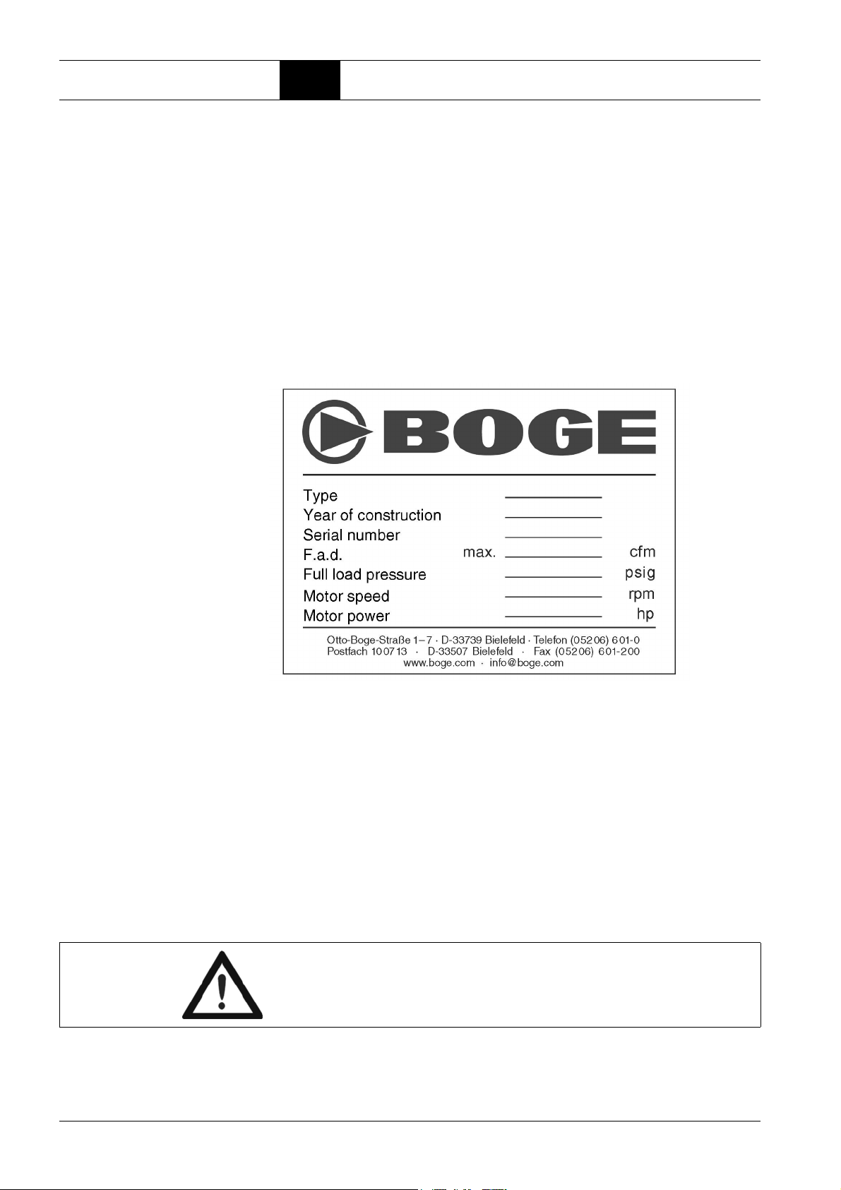
Enter the data of your compressor from the type plate or enclosed data sheet
in the illustration below. This will ensure that in the event of enquiries, you will
always have the most important data to hand.
m us within six days after ar-
Service
Fig. 1.1: Data on the type plate
Please do not hesitate to contact BOGE service if you have any questions.
Please call:
Telephone: +1-770-874-1570
Telephone: +49 5206 601-140
In the event of inquiries, always specify the
to prevent any delays:
–Type
– Year of manufacture
– Machine number
Attention!
Only BOGE service technicians or persons authorized by BOGE in writing
may repa
warranty claims will expire!
ir or alter the compressor during the warranty period. Otherwise all
following data of your compressor
Page 8 BOGE Operating instructions for C 10 L...C 20 L series screw compressors

Product description 2.1 Technical data
Part 2: Product description
2.1 Technical data
Technical data for C 10 L...C 20 L compressor assembly, part 1
Type C 10 L C 15 L C 20 L
Dimensions
– Width [inch] 46.1 52.5 52.5
– Depth [inch] 23.6 24.2 24.2
– Height [inch] 23.4 25.3 25.3
Weight
– silenced [lbs.] 313.2 361.4 361.4
Max. sound pressure level [± 3 dB(A)]
accord. to DIN 45635, part 13
– silenced / super silenced [dB(A)] 68 75 75
Reference surface measure
– silenced / super silenced [dB(A)] 13 13 13
Sound power level
– silenced / super silenced [dB(A)] 81 88 88
Compressor
max. final compression temperature [°F] 230 230 230
Volume flow according to
ISO 1217 appendix C at:
– p
= 115 psig [cfm] – 69 –
max
– p
= 150 psig [cfm] 36 – 77
max
Drive motor
Rated power [Hp] 10 15 20
Nominal speed
– 60 Hz [min
Protection type TEFC TEFC TEFC
ISO class F F F
Electrical connection
Mains voltage
Frequency
Recommended fuse protection
Mains voltage
Frequency
Recommended fuse protection
Mains voltage
Frequency
Recommended fuse protection
Mains voltage
Frequency
Recommended fuse protection
1)
Standard equipment. Mains voltages and frequencies are specified on a plate in the switch cabinet.
2)
The fuse values change in the case of other mains voltages and frequencies.
3)
Use fuse Class RK 5 only.
1)
1)
2) 3)
1)
1)
2) 3)
1)
1)
2) 3)
1)
1)
2) 3)
-1
] 1800 3600 3600
[V]
[Hz]
[A]
[V]
[Hz]
[A]
[V]
[Hz]
[A]
[V]
[Hz]
[A]
200
60
40
208 – 230
60
40
460
60
25
575
60
15
200
60
70
208 – 230
60
60
460
60
30
575
60
30
200
208 – 230
460
575
60
70
60
60
60
30
60
30
BOGE Operating instructions for C 10 L...C 20 L series screw compressors Page 9

Product description 2.2 Function description
Technical data for C 10 L...C 20 L compressor assembly, part 2
Type C 10 L C 15 L C 20 L
Oil filling quantity
Total oil filling quantity [gallon] 2.12 2.12 2.12
Oil topping up quantity
between min. + max. [gallon] 0.264 0.264 0.264
Intake air temperature
– min. [°F] + 41 + 41 + 41
– max. [°F] + 104 + 104 + 104
Cooling air requirement
– free-standing installation [cfm] 1765 2825 2825
Operating pressure values
(factory settings)
– p
= 115 psig: Switch-off press. p
max
Switch-on press. p
– p
= 150 psig: Switch-off press. p
max
Switch-on press. p
Safety valve
Activation pressure at:
– p
= 115 psig [psig] – 160 –
max
– p
= 150 psig [psig] 160 – 160
max
1)
Compressors for other operating pressures p
1)
[psig] – 115 –
max
[psig] – 100 –
min
[psig] 150 – 150
max
[psig] 135 – 135
min
= p
– 15 psig.
min
max
Function principle of the air end
2.2 Function description
The air end operates according to the displacement principle. In the housing,
the main and secondary screws are driven by means of an electric motor.
Both screws have screw-shaped profiles, intermeshing without contact.
Together with the housing wall, these screws form chambers which gradually
reduce in size, seen in air flow direction.
Rotation of the rotors causes the air taken in to be compressed to the final
pressure in the chambers.
During compression oil is continuously injected into the air end. This having a
cooling, sealing and lubricating function.
Page 10 BOGE Operating instructions for C 10 L...C 20 L series screw compressors

Product description 2.2 Function description
Air circuit
Fig. 2.1: Components of the air circuit
1 Intake filter
The intake filter cleans the air suctioned by the air end.
2 Intake regulator
The intake regulator opens (load operation) or closes (idling operation or
standstill) the suction line depending on the operating condition of the
compressor.
3 Air end
The air end compresses the sucked in air.
4 Compressed air/oil receiver
The compressed air separates from the oil under the force of gravity in the
compressed air/oil receiver.
5 Oil separator
The oil separator separates the residual oil contained in the compressed
air.
6 Minimum pressure check valve
The minimum pressure check valve does not open until the system pressure has increased to 51 psig. This causes a rapid build-up of the system
pressure and ensures lubrication in the starting phase. Once the com
pressor has been switched off, the check valve prevents the compressed
air from flowing back out of the mains line.
7* Compressed air after-cooler (air cooled)
The compressed air is cooled in the compressed air after-cooler, causing
the water contained in the air to condensate.
8 Stop valve
The screw compressor may be isolated from the mains by means of the
stop valve.
-
* Optionally for receiver systems without refrigeration compressed air dry-
ers
BOGE Operating instructions for C 10 L...C 20 L series screw compressors Page 11
Loading...