

Page 1

PROPRIETARY NOTE
THIS SPECIFICATION IS THE PROPERTY OF BOE OT AND SHALL NOT BE
REPRODUCED OR COPIED WITHOUT THE WRITTEN PERMISSION OF BOE OTAND
MUST BE RETURNED TO BOE OT UPON ITS REQUEST
TITLE : HT236F01-100
Preliminary Product Specification
P0
www.jxlcd.com
www.jxlcd.com
BEIJING BOE OPTOELECTRONICS TECHNOLOGY
SPEC. NUMBER
S
PRODUCT GROUP
TFT-LCD
P0
ISSUE DATE
2009.02.23.
PAGE
PAGE
1
OF 28
B2006-5006-O (1/3)
A4(210 X 297)
A4(210 X 297)
Page 2

PRODUCT GROUP
TFT- LCD PRODUCT P0 Feb..23 . 09’
REV
ISSUE DATE
REVISION HISTORY
REV. ECN No. DESCRIPTION OF CHANGES DATE PREPARED
P0 Initial Release Feb. 23. 09’ Wang Zhangtao
www.jxlcd.com
www.jxlcd.com
SPEC. NUMBER
S
B2006-5006-O (2/3) A4(210 X 297)
SPEC. TITLE
HT236F01-100 Preliminary Product Specification_P0
PAGE
2
OF 28
Page 3

PRODUCT GROUP
REV
ISSUE DATE
TFT- LCD PRODUCT
P0
Feb. 23. 09’
Contents
No. Item Page
1.0 General Description 4
2.0 Absolute Maximum Ratings 6
3.0 Electrical Specifications 7
4.0 Optical Specifications 8
5.0 Interface Connection 10
6.0 Signal Timing Specifications 13
7.0 Signal Timing Waveforms of Interface Signal 15
8.0 Input Signals, Display Colors & Gray Scale of Colors 17
9.0 Power Sequence 18
10.0 Mechanical Characteristics 19
www.jxlcd.com
11.0 Reliability Test 20
12.0 Handling& Cautions 21
13.0 Product Serial Number 22
14.0 Packing 23
15.0 Appendix 25
www.jxlcd.com
SPEC. NUMBER
S
B2006-5006-O (3/3)
SPEC. TITLE
HT236F01-100 Preliminary Product Specification_P0
PAGE
3
OF 28
A4(210 X 297)
Page 4
PRODUCT GROUP
REV
ISSUE DATE
TFT- LCD PRODUCT
P0
1.0 GENERAL DESCRIPTION
1.1 Introduction
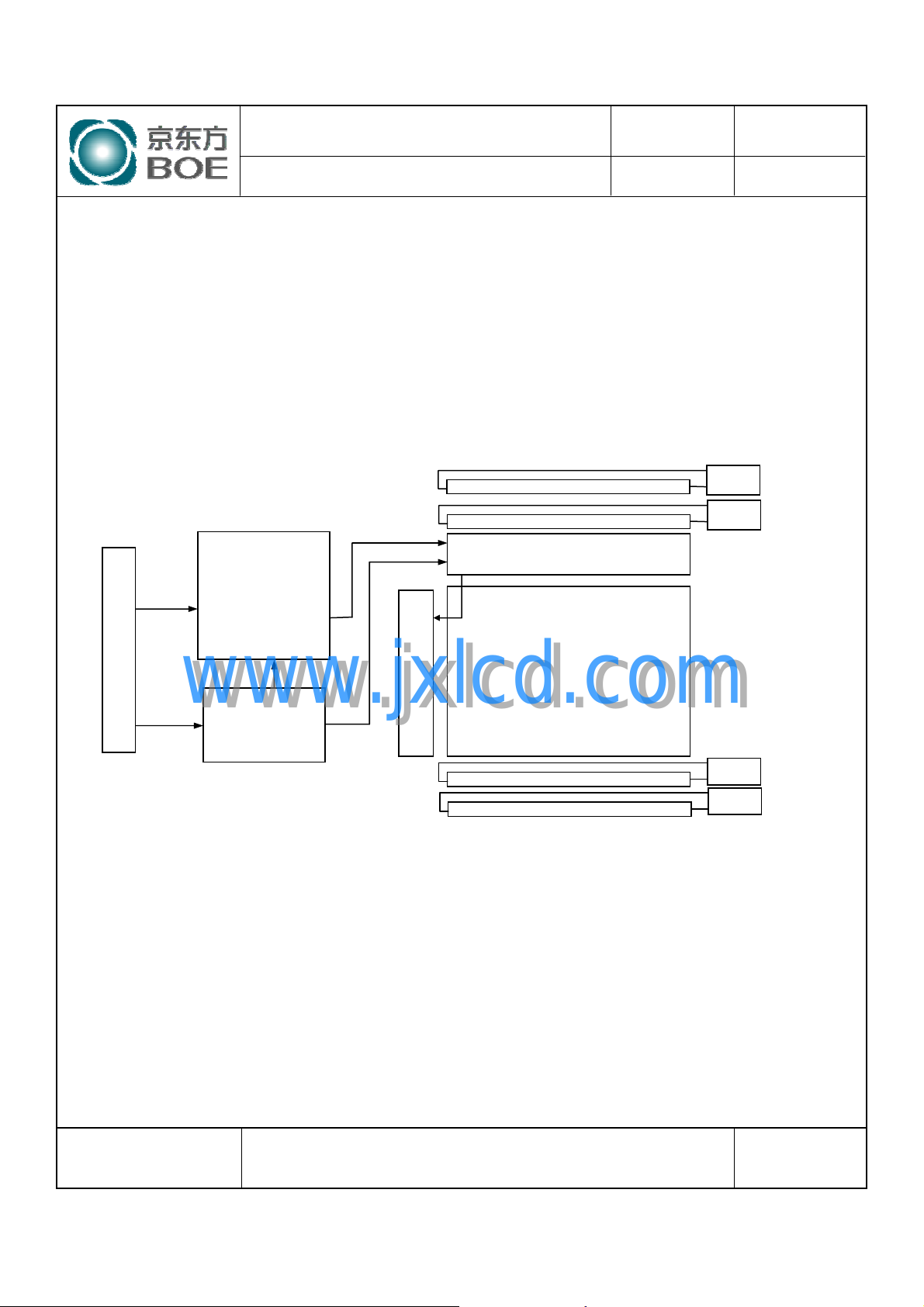
HT236F01-100 is a color active matrix TFT LCD module using amorphous silicon TFT's
(Thin Film Transistors) as an active switching devices. This module has a 23.6 inch
diagonally measured active area with FHD resolutions (1920 horizontal by 1080 vertical
pixel array). Each pixel is divided into RED, GREEN, BLUE dots which are arranged in
vertical stripe and this module can display 16.7M colors. The TFT-LCD panel used for this
module is adapted for a low reflection and higher color type.
CN21
CN22
Connector (CN
LVDS
Input
Signal
LVDS Rx
+
T/CON
+
Mini LVDS Tx
Gate Driver
Source Driver
TFT LCD Panel
Feb. 23. 09’
www.jxlcd.com
www.jxlcd.com
VDD
1
)
1.2 Features
z LVDS Interface with 2 pixel / clock
z High-speed response
z Low power consumption
z 6-bit (Hi-FRC) color depth, display 16. 7M colors
z Incorporated edge type back-light (Four lamps)
z High luminance and contrast ratio, low reflection and wide viewing angle
z DE (Data Enable) only
z RoHS /TCO’ 03 Compliant
DC/DC
Gamma
Vcom
1920 × 1080
CN23
CN24
SPEC. NUMBER
S
B2006-5006-O (3/3)
SPEC. TITLE
HT236F01-100 Preliminary Product Specification_P0
PAGE
4
OF 28
A4(210 X 297)
Page 5
PRODUCT GROUP
REV
ISSUE DATE
TFT- LCD PRODUCT
1.3 Application
z Desktop Type of PC & Workstation Use
z Slim-Size Display for Stand-alone Monitor
z Display Terminals for Control System
z Monitors for Process Controller
1.4 General Specification
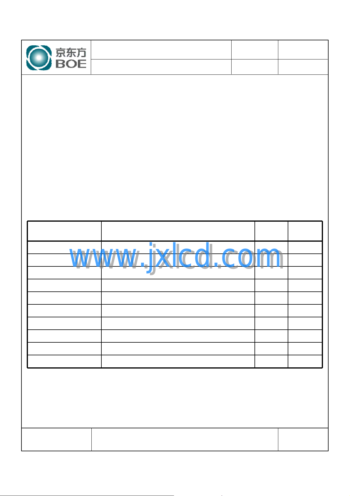
The followings are general specifications at the model HT236F01-100.
<Table 1. General Specifications>
Parameter Specification Unit
P0
Feb. 23. 09’
Remarks
Active area 521.28(H) × 293.22(V) mm
Number of pixels 1920(H) ×1080(V) pixels
Pixel pitch 0.2715(H) ×0.2715(V) mm
Pixel arrangement RGB Vertical stripe
Display colors 16.7M colors
Display mode Normally White
Dimensional outline 544.8(H) × 320.5(V) ×18.7(D) typ. mm
Weight 2900 (max.) g
Surface Treatment Haze 25%, 3H
Back-light Top/Bottom edge side, 4-CCFL type
www.jxlcd.com
www.jxlcd.com
SPEC. NUMBER
S
B2006-5006-O (3/3)
SPEC. TITLE
HT236F01-100 Preliminary Product Specification_P0
PAGE
5
OF 28
A4(210 X 297)
Page 6

PRODUCT GROUP
REV
ISSUE DATE
TFT- LCD PRODUCT
P0
2.0 ABSOLUTE MAXIMUM RATINGS
The followings are maximum values which, if exceed, may cause faulty operation or
damage to the unit. The operational and non-operational maximum voltage and current
values are listed in Table 2.
< Table 2. Absolute Maximum Ratings>
Symbol Min. Max. Unit Remarks
Parameter
Power Supply Voltage V
Logic Supply Voltage V
Back-light Lamp Current I
Back-light Lamp frequency F
Operating Temperature T
Storage Temperature T
BL
DD
IN
L
OP
ST
-0.3 6.0
VSS-0.3 VDD+0.3 V
38.0mA
40 80 kHz
0+50
-20 +60
[VSS=GND=0V]
V
℃
℃
Feb. 23. 09’
Ta = 25 ℃
1)
1)
Note : 1) Temperature and relative humidity range are shown in the figure below.
Wet bulb temperature should be 39 OC max. and no condensation of water.
www.jxlcd.com
www.jxlcd.com
Relative Humidity (%RH)
100
80
60
40
20
90
O perating R ange
Storage Range
5
0
(39,90)
(50,50)
(60,30)
20 40 60 80-2 0
Tem perature (˚C)
SPEC. NUMBER
S
B2006-5006-O (3/3)
SPEC. TITLE
HT236F01-100 Preliminary Product Specification_P0
PAGE
6
OF 28
A4(210 X 297)
Page 7

PRODUCT GROUP
REV
ISSUE DATE
TFT- LCD PRODUCT
3.0 ELECTRICAL SPECIFICATIONS
3.1Electrical Specifications
< Table 3. Electrical specifications >
Parameter Min. Typ. Max. Unit Remarks
Power Supply Voltage V
Power Supply Current I
In-Rush Current I
Permissible Input Ripple Voltage V
High Level Differential Input
Threshold Voltage
Low Level Differential Input
Threshold Voltage
Back-light Lamp Voltage V
Back-light Lamp Current I
Back-light Lamp operating Frequency F
Lamp Start Voltage
www.jxlcd.com
www.jxlcd.com
DD
DD
RUSH
RF
V
IH
V
IL
BL
BL
L
4.5 5.0 5.5 V
-100 - - mV
747 830 913 V
3.0 7.0 8.0 mA
40 - 80 KHz Note 3
P0
rms
rms
rms
rms
Note1
V
V
25℃, Note 4
0℃, Note 4
-TBDTBDmA
- 2.0 3.0 A Note 2
- - 100 mV VDD= 5.0V
- - +100 mV
mV600-200|VID|Differential input voltage
1.51.21.0VcmDifferential input common mode voltage
- - 1430 V
- - 1800 V
Feb. 23. 09’
[Ta =25±2 ℃]
=100mV,
IH
=-100mV
IL
Lamp Life 40,000 50,000 - Hrs I
P
D
Power Consumption
Notes : 1. The supply voltage is measured and specified at the interface connector of LCM.
The current draw and power consumption specified is for VDD=5.0V, Frame rate=75Hz and
Clock frequency = 92.9 MHz. Test Pattern of power supply current
a) Typ : Color Bar pattern
b) Max : Skip Sub Pixel Pattern
P
BL
P
total
- T.B.D T.B.D W
- 23.24 W IBL=7.0 mA, Note 5
- T.B.D T.B.D W
2. Duration of rush current is about 2 ms and rising time of VDD is 520 μs ± 20 %
3. The lamp frequency should be selected as different as possible from the horizontal
synchronous frequency and its harmonics to avoid interference, which may cause line flow on the display
4. The voltage above this value should be applied to the lamps for more than 1 second to start-up. Otherwise the
lamps may not be turned on.
5. Calculated value for reference (V
SPEC. NUMBER
S
SPEC. TITLE
HT236F01-100 Preliminary Product Specification_P0
× IBL) ×4 excluding inverter loss.
BL
B2006-5006-O (3/3)
= 7.0 mA
BL
7
A4(210 X 297)
PAGE
OF 28
Page 8
PRODUCT GROUP
REV
ISSUE DATE
TFT- LCD PRODUCT
P0
Feb. 23. 09’
4.0 OPTICAL SPECIFICATION
4.1 Overview
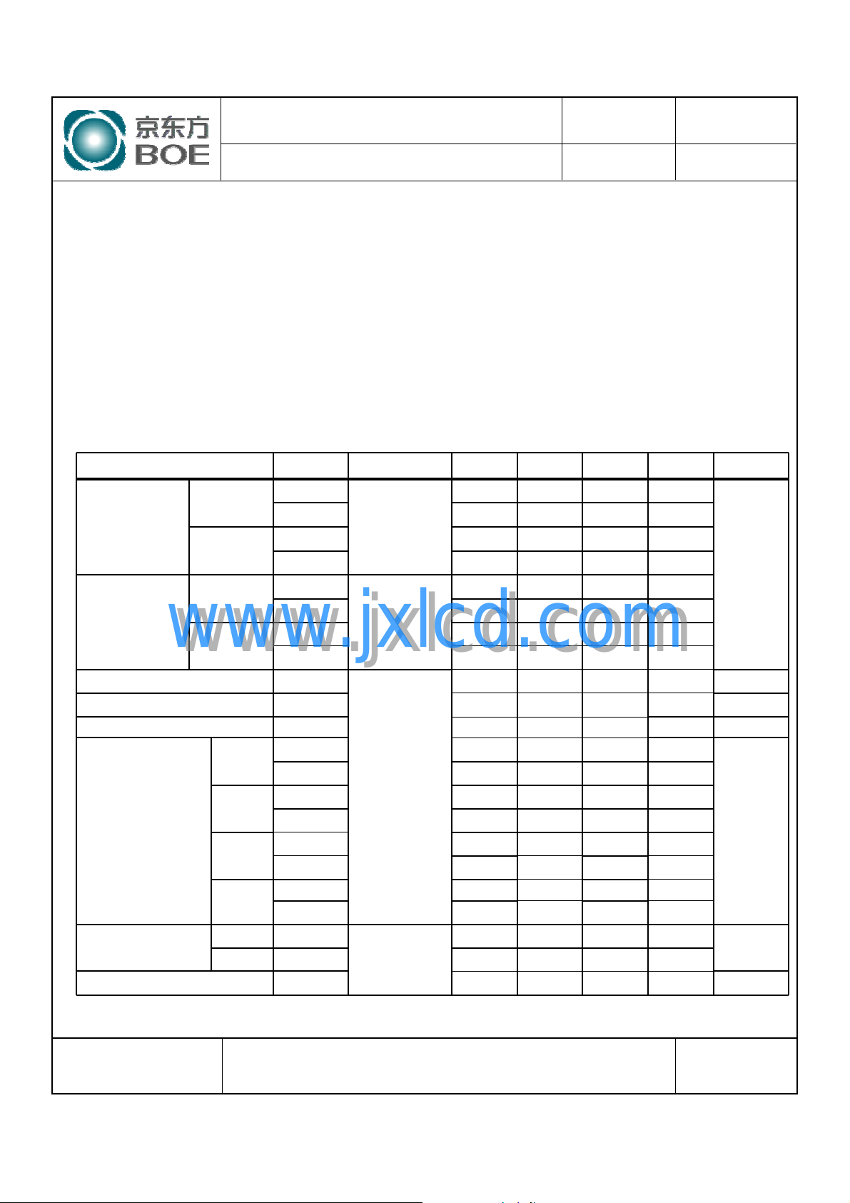
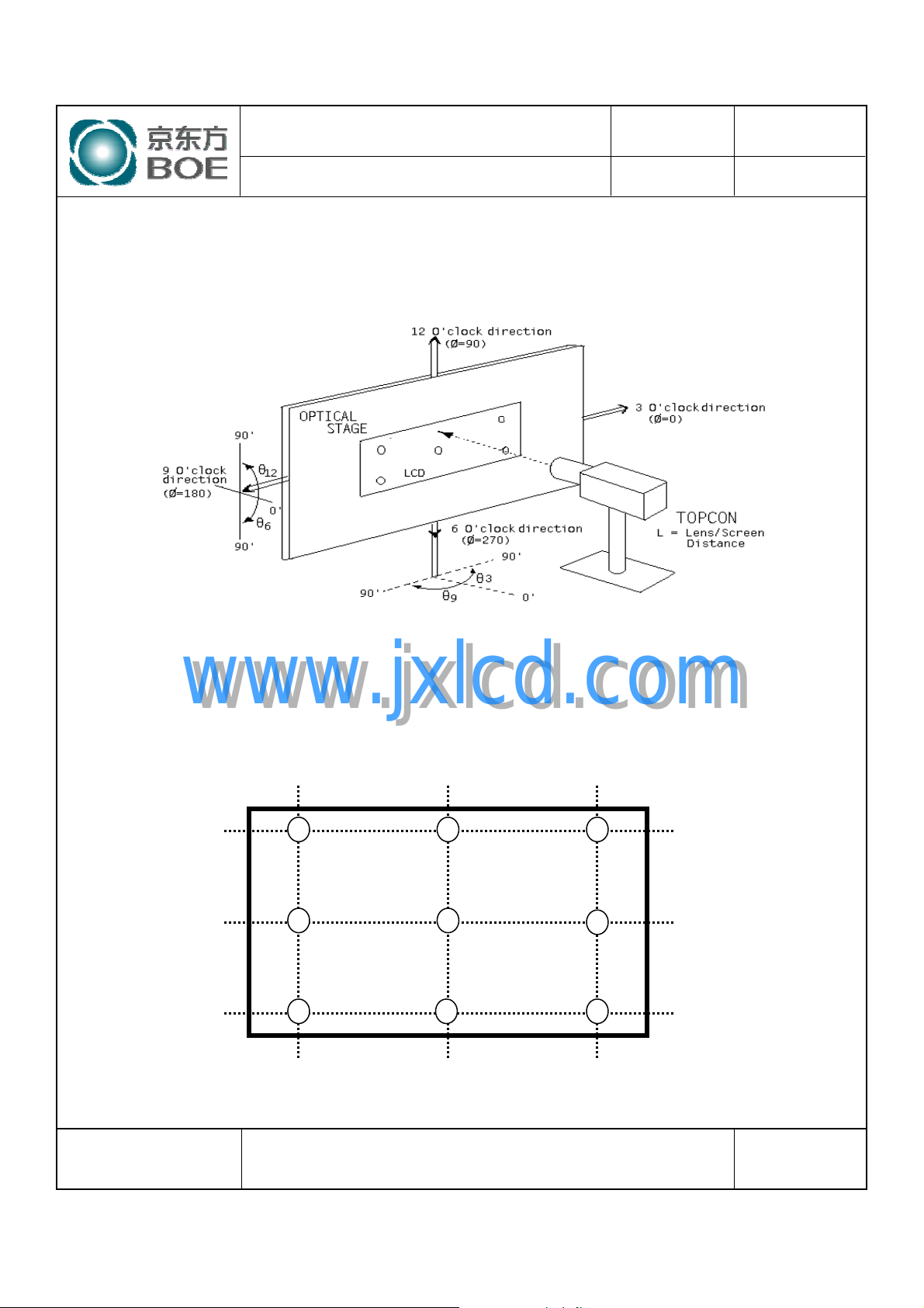
The test of Optical specifications shall be measured in a dark room (ambient luminance ≤ 1 lux and temperature =
25±2℃) with the equipment of Luminance meter system (Goniometer system and TOPCONE BM-5) and test unit shall
be located at an approximate distance 50cm from the LCD surface at a viewing angle of θ and Φ equal to 0°. We refer
to θ
θ
(=θ3) as the 3 o’clock direction (the “right”), θ
Ø=0
) as the 9 o’clock direction (“left”) and θ
9
(= θ6 ) as the 6 o’clock direction (“bottom”). While scanning θ and/or
Ø=270
Ø, the center of the measuring spot on the Display surface shall stay fixed. The measurement shall be executed after 30
minutes warm-up period. VDD shall be 5.0V +/-10% at 25°C. Optimum viewing angle direction is 6 ’clock.
4.2 Optical Specifications
[VDD = 5.0V, Frame rate = 60Hz, Clock = 74.25MHz, IBL= 7.5mA, Ta =25±2 ℃]
Parameter Symbol Condition Min. Typ. Max. Unit Remark
Θ
Horizontal
Viewing Angle range
Vertical
Horizontal
Viewing Angle range
www.jxlcd.com
Luminance Contrast ratio CR
Luminance of White Y
White luminance uniformity ΔY7580%Note 4
Reproduction
of color
Response
Time
Cross Talk CT - - 2.0 % Note 7
Vertical
www.jxlcd.com
White
Red
Green
Blue
Rising T
Falling T
3
Θ
9
Θ
12
Θ
6
Θ
3
Θ
9
Θ
12
Θ
6
w
W
x
W
y
R
x
R
y
G
x
G
y
B
x
B
y
r
f
CR > 10
CR > 5
Θ = 0°
(Center)
Normal
Viewing
Angle
(= θ12) as the 12 o’clock direction (“upward”), θ
Ø=90
70 85 - Deg.
70 85 - Deg.
70 80 - Deg.
70 80 - Deg.
85 - - Deg.
85 - - Deg.
85 - - Deg.
85 - - Deg.
700 1000 Note 2
250 300 cd/m
0.283 0.313 0.343
0.299 0.329 0.359
0.614 0.644 0.674
0.336
0.285
0.593
0.141
0.076
1.5 2.5 ms
3.5 5.5 ms
0.3660.306
0.3150.255
0.6230.563
0.1710.111
0.1060.046
(=
Ø=180
Note 1
2
Note 3
Note 5
Note 6
SPEC. NUMBER
S
B2006-5006-O (3/3)
SPEC. TITLE
HT236F01-100 Preliminary Product Specification_P0
PAGE
8
OF 28
A4(210 X 297)
Page 9

PRODUCT GROUP
REV
ISSUE DATE
TFT- LCD PRODUCT
P0
Feb. 23. 09’
Note :
1. Viewing angle is the angle at which the contrast ratio is greater than 10. The viewing are
determined for the horizontal or 3, 9 o’clock direction and the vertical or 6, 12 o’clock
direction with respect to the optical axis which is normal to the LCD surface.
2. Contrast measurements shall be made at viewing angle of θ= 0° and at the cent er of the LCD
surface. Luminance shall be measured with all pixels in the view field set first to white, then
to the dark (black) state. (See FIGURE 1 shown in Appendix) Luminance Contrast Ratio
(CR) is defined mathematically.
CR =
3. Center Luminance of white is defined as the LCD surface. Luminance shall be measured with
all pixels in the view field set first to white. This measurement shall be taken at the locations
shown in FIGURE 2 for a total of the measurements per display.
4. The White luminance uniformity on LCD surface is then expressed as :
ΔY = ( Minimum Luminance of 9points / Maximum Luminance of 9points ) * 100
(See FIGURE 2 shown in Appendix).
5. The color chromaticity coordinates specified in Table 4. shall be calculated from the spectral
6. The electro-optical response time measurements shall be made as FIGURE 3 shown in
7. Cross-Talk of one area of the LCD surface by another shall be measured by comparing the
www.jxlcd.com
data measured with all pixels first in red, green, blue and white. Measurements shall be made
at the center of the panel.
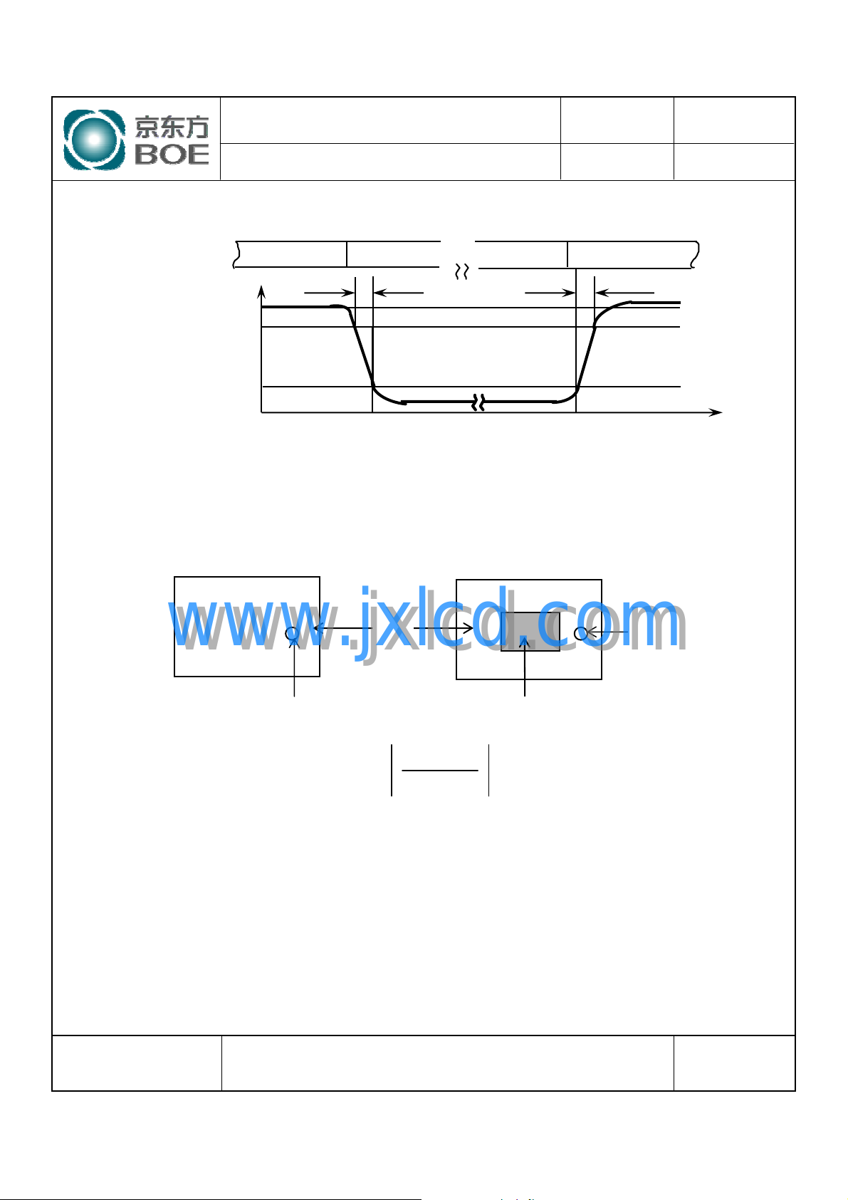
Appendix by switching the “data” input signal ON and OFF. The times needed for the
luminance to change from 10% to 90% is Td, and 90% to 10% is Tr.
luminance (Y
luminance (YB) of that same area when any adjacent area is driven dark. (See FIGURE 4
shown in Appendix).
www.jxlcd.com
) of a 25mm diameter area, with all display pixels set to a gray level, to the
A
Luminance when displaying a white raster
Luminance when displaying a black raster
SPEC. NUMBER
S
B2006-5006-O (3/3)
SPEC. TITLE
HT236F01-100 Preliminary Product Specification_P0
PAGE
9
OF 28
A4(210 X 297)
Page 10
PRODUCT GROUP
REV
ISSUE DATE
TFT- LCD PRODUCT
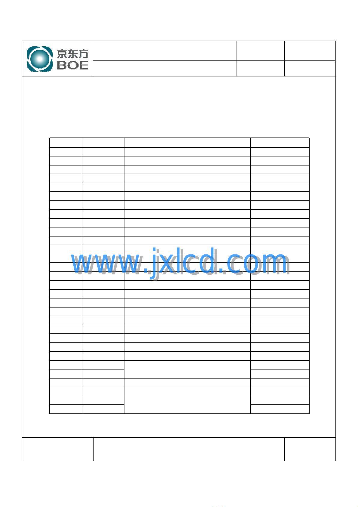
5.0 INTERFACE CONNECTION.
5.1 Electrical Interface Connection
●
CN11 Module Side Connector : UJU IS100-30O-C23 or Equivalent
User Side Connector : JAE FI-X30H or Equivalent
Pin No Symbol Function Remark
1 RXO0- Negative Transmission data of Pixel 0 (ODD)
2 RXO0+ Positive Transmission data of Pixel 0 (ODD)
3 RXO1- Negative Transmission data of Pixel 1 (ODD)
4 RXO1+ Positive Transmission data of Pixel 1 (ODD)
5 RXO2- Negative Transmission data of Pixel 2 (ODD)
6 RXO2+ Positive Transmission data of Pixel 2 (ODD)
7 GND Power Ground
8 RXOC- N egative Transmission Clock (ODD)
9 RXOC+ Positive Transmission Clock (ODD)
10 RXO3- Negative Transmission data of Pixel 3 (ODD)
11 RXO3+ Positive Transmission data of Pixel 3 (ODD)
12 RXE0- Negative Transmission data of Pixel 0 (EVEN)
13 RXE0+ Positive Transmission data of Pixel 0 (EVEN)
14 GND Power Ground
www.jxlcd.com
www.jxlcd.com
15 RXE1- Negative Transmission data of Pixel 1 (EVEN)
16 RXE1+ Positive Transmission data of Pixel 1 (EVEN)
17 GNG Power Ground
18 RXE2- Negative Transmission data of Pixel 2 (EVEN)
19 RXE2+ Positive Transmission data of Pixel 2 (EVEN)
20 RXEC- Negative Tr ansmission Clock (EVEN)
21 RXEC+ Positive Transmission Clock (EVEN)
22 RXE3- Negative Transmission data of Pixel 3 (EVEN)
23 RXE3+ Positive Transmission data of Pixel 3 (EVEN)
24 GND Power Ground Note 1
25 (CE) LCD internal use only Internal Use
26 (CTL) Internal Use
27 NC No. Connection
28 VDD
30 VDD
P0
Power Supply: +5V29 VDD
Feb. 23. 09’
SPEC. NUMBER
S
B2006-5006-O (3/3)
SPEC. TITLE
HT236F01-100 Preliminary Product Specification_P0
PAGE
10
OF 28
A4(210 X 297)
Page 11
PRODUCT GROUP
REV
ISSUE DATE
TFT- LCD PRODUCT
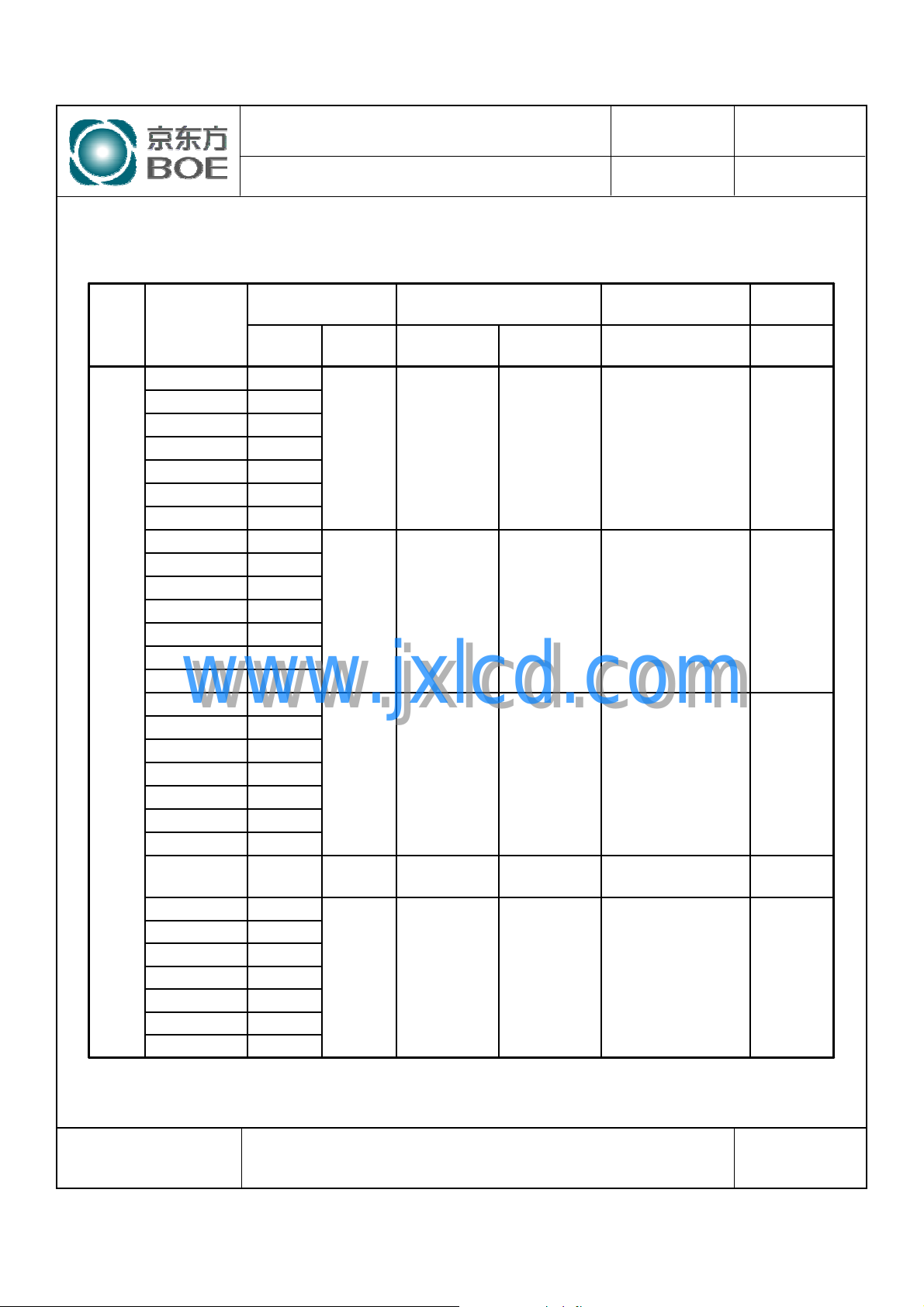
5.2 LVDS Interface (Tx; THC63LVDF83A or Equivalent)
5.2.1 LVDS Interface
OUT0-
OUT1-
OUT2-
OUT3-
Interface
TFT-LCD
(Rx)
RXO0-
RXO0+
RXO1-
RXO1+
RXO2-
RXO2+
RXO CLK-
RXO CLK+
RXO3-
RXO3+
Input
Signal
OR0
OR1
OR2
OR3
OR4
OR5
OG0
OG1
OG2
OG3
OG4
OG5
OB0
L
V
D
S
OB1
www.jxlcd.com
www.jxlcd.com
OB2
OB3
OB4
OB5
Hsync
Vsync
DE
MCLK
OR6
OR7
OG6
OG7
OB6
OB7
RSVD
Transmitter Remark
Pin No.
51
52
54
55
56
3
4
6
7
11
12
14
15
19
20
22
23
24
27
28
30
31
50
2
8
10
16
18
25
Pin No.
48
47
46
45
42
41
40
39
38
37
System (Tx)
OUT0+
OUT1+
OUT2+
CLK OUT-
CLK OUT+
OUT3+
P0
HT236F01-100
(CN11)
Pin No.
1
2
3
4
5
6
8
9
10
11
Feb. 23. 09’
SPEC. NUMBER
S
B2006-5006-O (3/3)
SPEC. TITLE
HT236F01-100 Preliminary Product Specification_P0
PAGE
11
OF 28
A4(210 X 297)
Page 12
PRODUCT GROUP
REV
ISSUE DATE
TFT- LCD PRODUCT
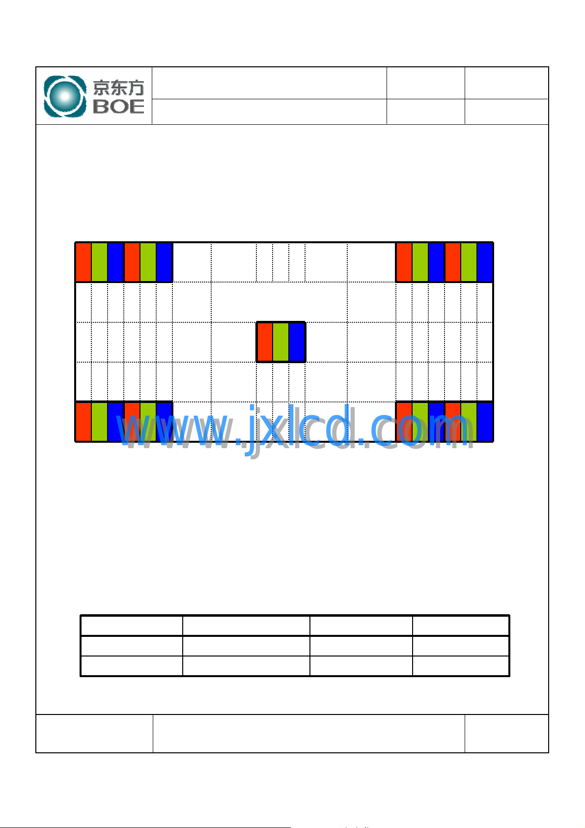
5.3 Data Input Format
(1,1) (2,1) (1919,1) (1920,1)
R G B R G B R G B R G B
1 Pixel = 3 Dots
R G B
P0
Feb. 23. 09’
R G B R G B R G B R G B
www.jxlcd.com
(1,1080) (2,1080) (1919,1080) (1920,1080)
5.4 Back-light Interface Connection
www.jxlcd.com
Display Position of Input Data (V-H)
:35001HS-02L (Yeon Ho) or EquivalentModule Side Connector●CN 21,22
User Side Connector
:35001WR-02L(Yeon Ho) or Equivalent
FUNCTIONCOLORINPUTPIN NO.
High VoltagePink or BlueHOT1
GroundWhite or GrayCOLD2
SPEC. NUMBER
S
B2006-5006-O (3/3)
SPEC. TITLE
HT236F01-100 Preliminary Product Specification_P0
PAGE
12
OF 28
A4(210 X 297)
Page 13
PRODUCT GROUP
REV
ISSUE DATE
TFT- LCD PRODUCT
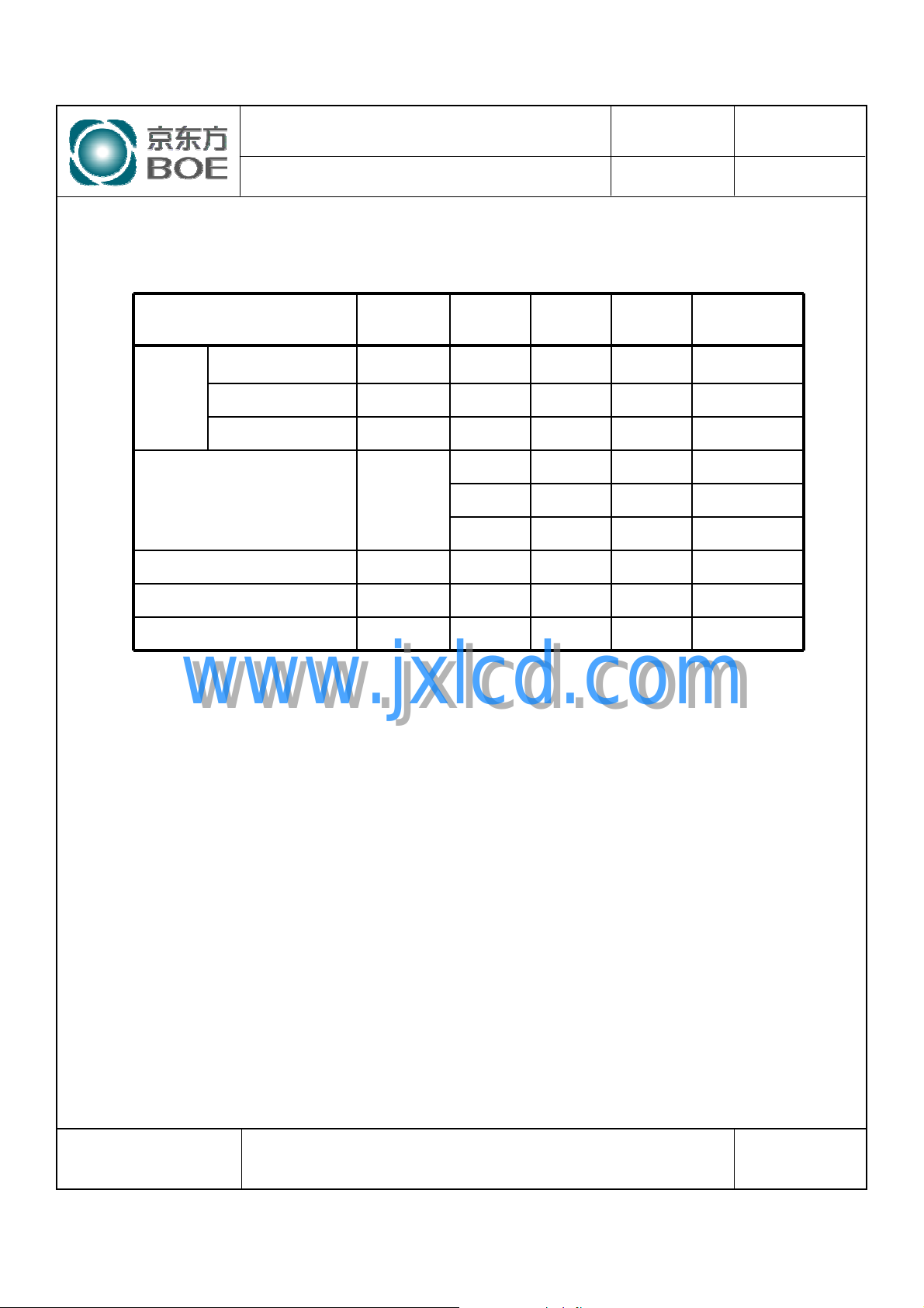
6.0 SIGNAL TIMING SPECIFICATION
The HT236F01-100 is operated by the DE only.
6.1
Item Symbols Min Typ Max Unit
Frequency 1/Tc 58.54 74.25 98 MHz
Clock
Frame Period Tv
Vertical Display Period Tvd - 1080 - lines
One line Scanning Period Th 1050 1100 1150 clocks
High Time Tch - 4/7Tc Low Time Tcl - 4/7Tc -
P0
1115 1126 1136 lines
50 60 75 Hz
20 16.7 13.3 ms
Feb. 23. 09’
Horizontal Display Period Thd 960 960 960 clocks
www.jxlcd.com
www.jxlcd.com
SPEC. NUMBER
S
B2006-5006-O (3/3)
SPEC. TITLE
HT236F01-100 Preliminary Product Specification_P0
PAGE
13
OF 28
A4(210 X 297)
Page 14
PRODUCT GROUP
REV
ISSUE DATE
TFT- LCD PRODUCT
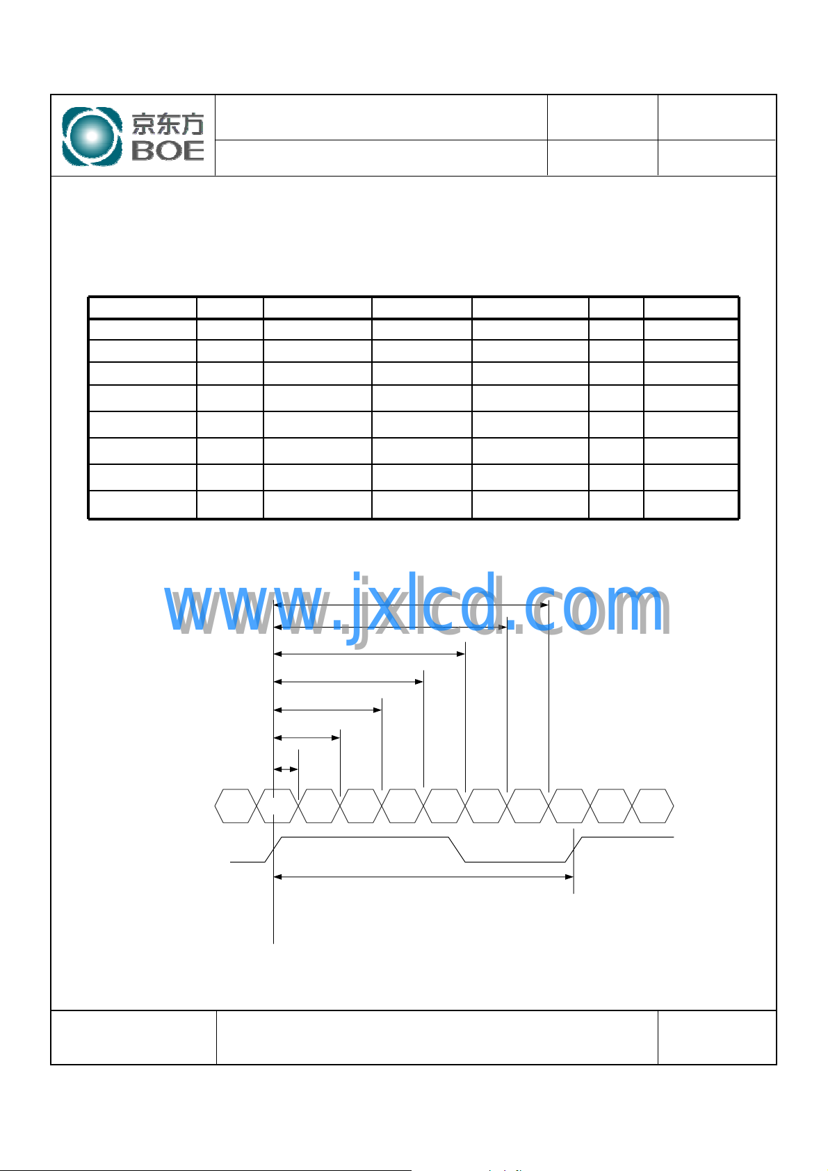
6.2 LVDS Rx Interface Timing Parameter
The specification of the LVDS Rx interface timing parameter is shown in Table 4.
<Table 4. LVDS Rx Interface Timing Specification>
Item Symbol Min Typ Max Unit Remark
CLKIN Period tRCIP 10.20 13.47 17.08 nsec
Input Data 0 tRIP1 -0.4 0.0 +0.4 nsec
Input Data 1 tRIP0 tRCIP/7-0.4 tRCIP/7 tRCIP/7+0.4 nsec
Input Data 2 tRIP6 2 ×tRCIP/7-0.4 2 ×tRCIP/7 2 ×tRCIP/7+0.4 nsec
Input Data 3 tRIP5 3 ×tRCIP/7-0.4 3 ×tRCIP/7 3 ×tRCIP/7+0.4 nsec
Input Data 4 tRIP4 4 ×tRCIP/7-0.4 4 ×tRCIP/7 4 ×tRCIP/7+0.4 nsec
Input Data 5 tRIP3 5 ×tRCIP/7-0.4 5 ×tRCIP/7 5 ×tRCIP/7+0.4 nsec
Input Data 6 tRIP2 6 ×tRCIP/7-0.4 6 ×tRCIP/7 6 ×tRCIP/7+0.4 nsec
P0
Feb. 23. 09’
tRIP2
tRIP4
tRIP5
tRIP3
tRCIP
Vdiff=0[v]Vdiff=0[v]
www.jxlcd.com
www.jxlcd.com
tRIP6
tRIP0
tRIP1
RXz +/-
* Z = 0, 1, 2,3
RxCLK+
* Vdiff = (RXz+)-(RXz-),…. ,(RXCLK+)-(RXCLK-)
Rx2 Rx1 Rx0 Rx6 Rx5 Rx4 Rx3 Rx2 Rx1 Rx0Rx3
SPEC. NUMBER
S
B2006-5006-O (3/3)
SPEC. TITLE
HT236F01-100 Preliminary Product Specification_P0
PAGE
14
OF 28
A4(210 X 297)
Page 15
PRODUCT GROUP
REV
ISSUE DATE
TFT- LCD PRODUCT
P0
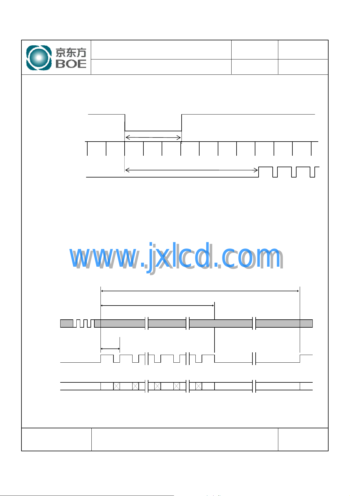
7.0 SIGNAL TIMING WAVEFORMS OF INTERFACE SIGNAL
7.1 Sync Timing Waveforms
V-Sync
H-Sync
DE
1) Need over 3 H-sync during V-Sync Low
2) Fix H-Sync width from V-Sync falling edge to first rising edge
Over 3 H-sync
Fix H-Sync width Area
Feb. 23. 09’
7.2 Vertical Timing Waveforms
www.jxlcd.com
www.jxlcd.com
MCLK
Th
DE
R7 ~ R0
G7 ~ G0
B7 ~ B0
Invalid Data DataInvalid
x,1 x,2 x,y x+1,1
Tv
Tvd
x,1050
SPEC. NUMBER
S
B2006-5006-O (3/3)
SPEC. TITLE
HT236F01-100 Preliminary Product Specification_P0
PAGE
15
OF 28
A4(210 X 297)
Page 16
PRODUCT GROUP
REV
ISSUE DATE
TFT- LCD PRODUCT
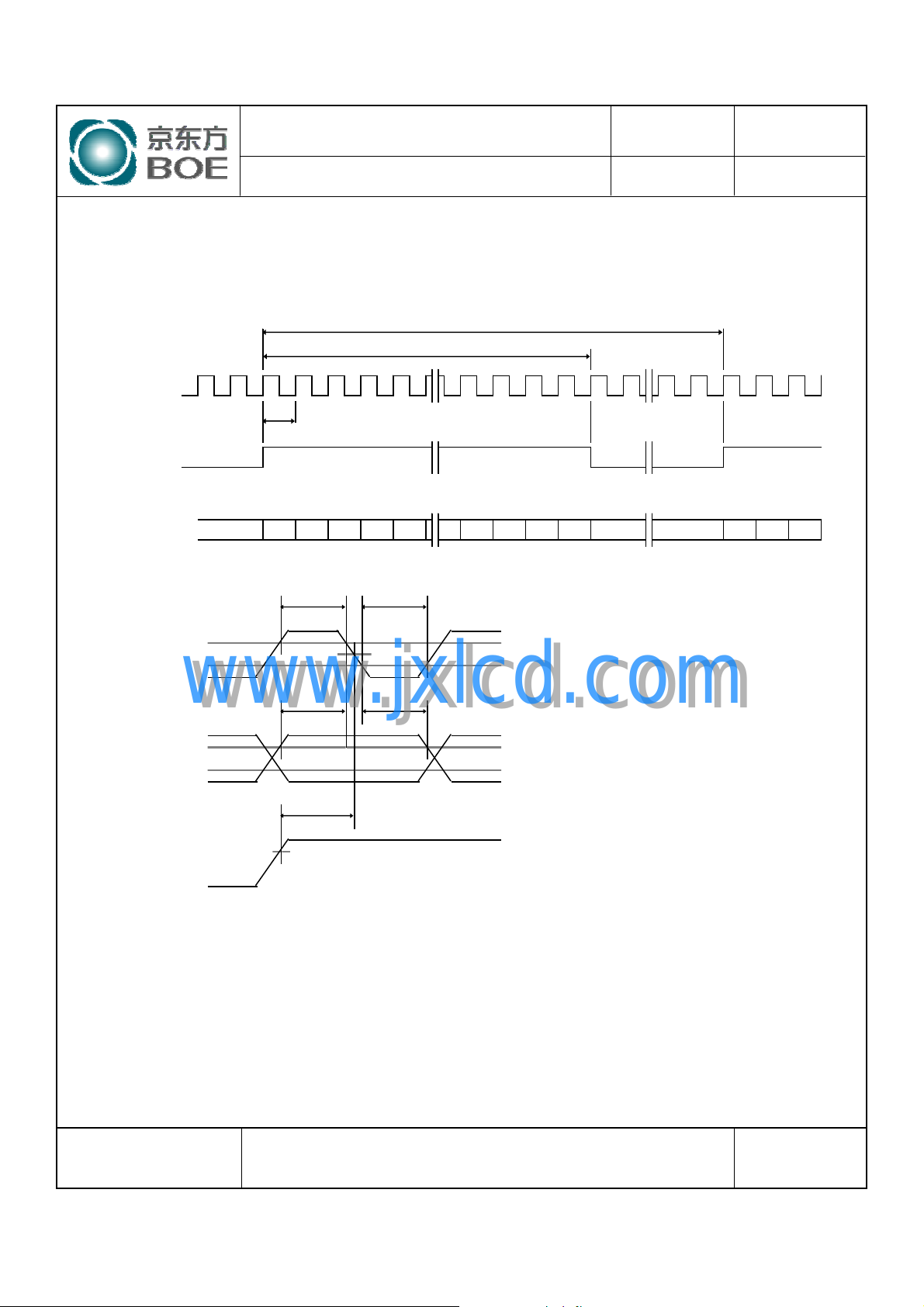
7.3 Horizontal Timing Waveforms
MCLK
Tc
DE
RA7 ~RA0
GA7 ~GA0
BA7 ~BA0
D1 D2 Dn Data D1 D2 D3
Tch
Thd
Tcl
Th
D1048 D1049 D1050
P0
Invalid
Feb. 23. 09’
2.0V
MCLK
www.jxlcd.com
www.jxlcd.com
Data
DE
Tds
Valid
Tes
2.0V
1.5V
Tdh
Data
0.8V
2.0V
0.8V
SPEC. NUMBER
S
B2006-5006-O (3/3)
SPEC. TITLE
HT236F01-100 Preliminary Product Specification_P0
PAGE
16
OF 28
A4(210 X 297)
Page 17
PRODUCT GROUP
REV
ISSUE DATE
TFT- LCD PRODUCT
P0
Feb. 23. 09’
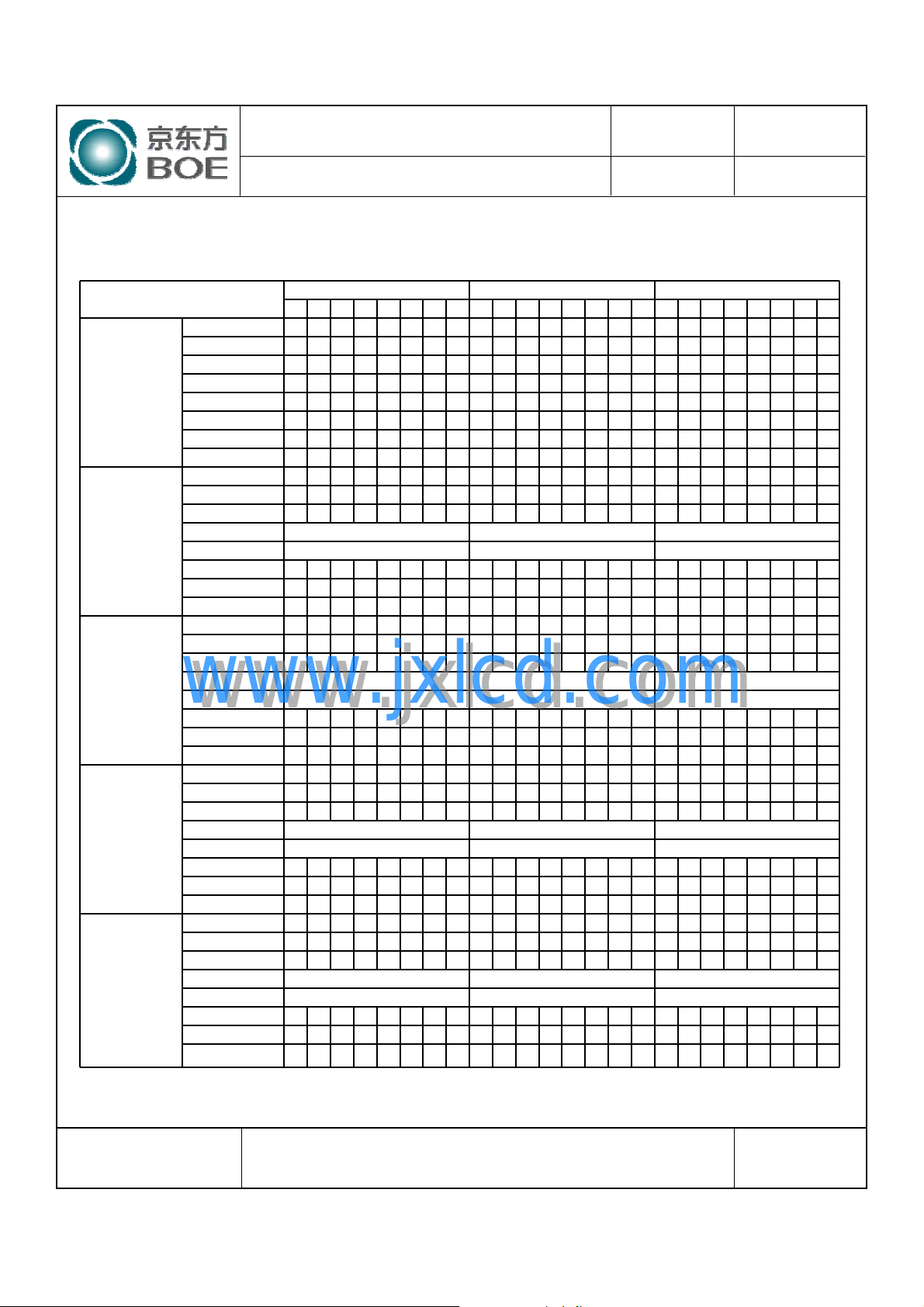
8.0 INPUT SIGNALS, BASIC DISPLAY COLORS & GRAY SCALE OF COLORS
Color & Gray Scale
Basic Colors
Gray Scale
of RED
Gray Scale
of GREEN
Gray Scale
of BLUE
Gray Scale
of WHITE
R7 R6 R5 R4 R3 R2 R1 R0 G7 G6 G5 G4 G3 G2 G1 G0 B7 B6 B5 B4 B3 B2 B1 B0
Black 000000000000000000000000
Blue 000000000000000011111111
Green 000000001111111100000000
Cyan 000000001111111111111111
Red 111111110000000000000000
Magenta 111111110000000011111111
Yellow 111111111111111100000000
White 111111111111111111111111
Black 000000000000000000000000
△
Darker 000000100000000000000000
△↑ ↑ ↑
▽↓ ↓ ↓
Brighter 111111010000000000000000
▽
Red 111111110000000000000000
Black 000000000000000000000000
△
Darker 000000000000001000000000
△↑ ↑ ↑
www.jxlcd.com
▽↓ ↓ ↓
www.jxlcd.com
Brighter 000000001111110100000000
▽
Green 000000001111111100000000
Black 000000000000000000000000
△
Darker 000000000000000000000010
△↑ ↑ ↑
▽↓ ↓ ↓
Brighter 000000000000000011111101
▽
Blue 000000000000000011111111
Black 000000000000000000000000
△
Darker 000000100000001000000010
△↑ ↑ ↑
▽↓ ↓ ↓
Brighter 111111011111110111111101
▽
White 111111111111111111111111
RED DATA GREEN DATA BLUE DATA
000000010000000000000000
111111100000000000000000
000000000000000100000000
000000001111111000000000
000000000000000000000001
000000000000000011111110
000000010000000100000001
111111101111111011111110
SPEC. NUMBER
S
B2006-5006-O (3/3)
SPEC. TITLE
HT236F01-100 Preliminary Product Specification_P0
PAGE
17
OF 28
A4(210 X 297)
Page 18
PRODUCT GROUP
REV
ISSUE DATE
TFT- LCD PRODUCT
P0
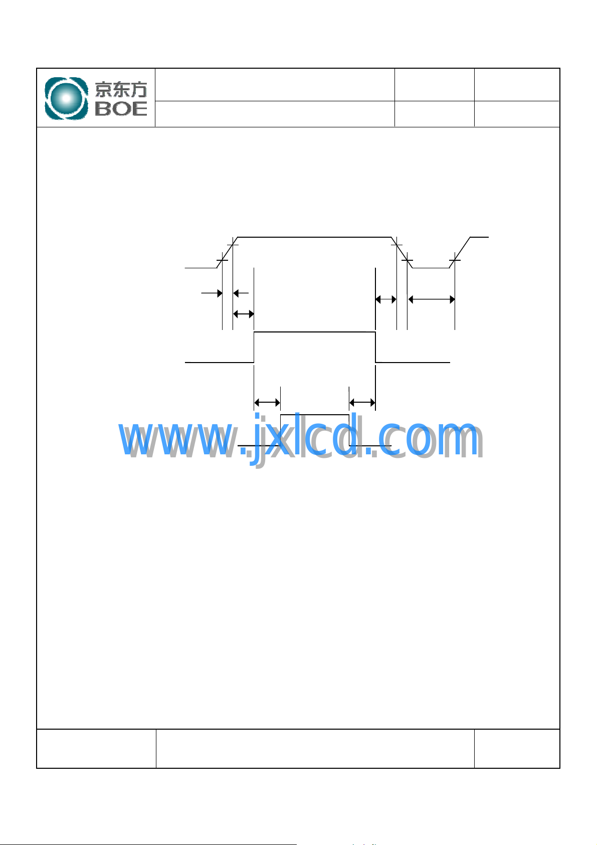
9.0 POWER SEQUENCE
To prevent a latch-up or DC operation of the LCD module, the power on/off sequence
shall be as shown in below
Power Supply
Interface Signal
0.9VDD
0.1VDD
0V
T1
T2
Valid
0V
T5 T6
0.9VDD
T3
0.1VDD
T4
Feb. 23. 09’
Back- light
● 0.5 ms ≤ T1 ≤ 10 ms
● 0 ≤ T2 ≤ 50 ms
● 0 ≤ T3 ≤ 50 ms
● 1 sec ≤ T4
● 200 ms ≤ T5
● 200 ms ≤ T6
www.jxlcd.com
www.jxlcd.com
0V
Notes:
1. When the power supply VDD is 0V, keep the level of input signals on
the low or keep high impedance.
2. Do not keep the interface signal high impedance when power is on.
3. Back Light must be turn on after power for logic and interface signal are valid.
SPEC. NUMBER
S
B2006-5006-O (3/3)
SPEC. TITLE
HT236F01-100 Preliminary Product Specification_P0
PAGE
18
OF 28
A4(210 X 297)
Page 19
PRODUCT GROUP
REV
ISSUE DATE
TFT- LCD PRODUCT
P0
10.0 MECHANICAL CHARACTERISTICS
10.1 Dimensional Requirements
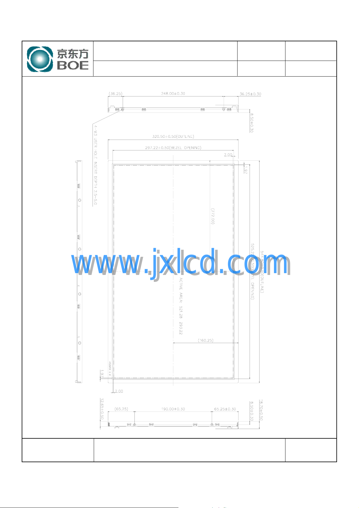
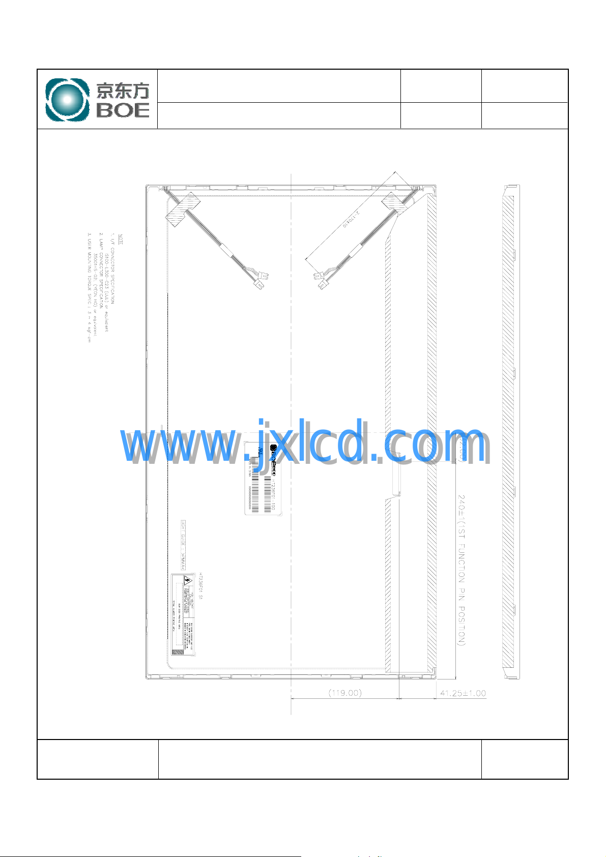
FIGURE 6 (located in Appendix) shows mechanical outlines for the model HT236F01-100.
Other parameters are shown in Table 5.
<Table 5. Dimensional Parameters>
Parameter Specification Unit
Dimensional outline
Weight
Active area
Pixel pitch
Number of pixels
Back-light
544.8×320.5×18.7
2900 (max.)
521.28 (H) × 293.22 (V)
0.2715 (H) ×0.2715 (V)
1920 (H)×1080 (V) (1 pixel = R + G + B dots)
Top / Bottom edge side 4-CCFL type
Feb. 23. 09’
mm
gram
mm
mm
pixels
www.jxlcd.com
www.jxlcd.com
10.2 Mounting
See FIGURE 5. (shown in Appendix)
10.3 Anti-Glare and Polarizer Hardness.
The surface of the LCD has an anti-glare coating to minimize reflection and a coating to reduce
scratching.
10.4 Light Leakage
There shall not be visible light from the back-lighting system around the edges of the screen as
seen from a distance 50cm from the screen with an overhead light level of 350lux.
SPEC. NUMBER
S
B2006-5006-O (3/3)
SPEC. TITLE
HT236F01-100 Preliminary Product Specification_P0
PAGE
19
OF 28
A4(210 X 297)
Page 20
PRODUCT GROUP
REV
ISSUE DATE
TFT- LCD PRODUCT
11.0 RELIABLITY TEST
The Reliability test items and its conditions are shown in below.
<Table 6. Reliability Test Parameters >
No Test Items
High temperature storage test Ta = 60 ℃, 240 hrs
1
Low temperature storage test Ta = -20 ℃, 240 hrs
2
High temperature & high humidity
3
operation test
High temperature operation test Ta = 50 ℃, 240hrs
4
Low temperature operation test Ta = 0 ℃, 240hrs
5
Thermal shock Ta = -20 ℃↔60 ℃ (0.5 hr), 100 cycle
6
Vibration test
7
(non-operating)
Ta = 50 ℃, 80%RH, 240hrs
Frequency
Gravity / AMP 1.5 G
Period X, Y, Z 30 min
P0
Conditions
Sine wave,10 ~ 300 Hz,
Sweep rate 30 min
Feb. 23. 09’
www.jxlcd.com
www.jxlcd.com
Shock test
8
(non-operating)
Electro-static discharge test
9
(non-operating)
Gravity
Pulse width
Direction ±X, ±Y, ±Z Once for each
Air : 150 pF, 330Ω, 15 KV
Contact : 150 pF, 330Ω, 8 KV
50G
11msec, sine wave
SPEC. NUMBER
S
B2006-5006-O (3/3)
SPEC. TITLE
HT236F01-100 Preliminary Product Specification_P0
PAGE
20
OF 28
A4(210 X 297)
Page 21
PRODUCT GROUP
REV
ISSUE DATE
TFT- LCD PRODUCT
12.0 HANDLING & CAUTIONS
(1) Cautions when taking out the module
y Pick the pouch only, when taking out module from a shipping package.
(2) Cautions for handling the module
y As the electrostatic discharges may break the LCD module, handle the LCD
module with care. Peel a protection sheet off from the LCD panel surface as
slowly as possible.
y As the LCD panel and back - light element are made from fragile glass material,
impulse and pressure to the LCD module should be avoided.
y As the surface of the polarizer is very soft and easily scratched, use a soft dry
cloth without chemicals for cleaning.
y Do not pull the interface connector in or out while the LCD module is operating.
y Put the module display side down on a flat horizontal plane.
y Handle connectors and cables with care.
(3) Cautions for the operation
y When the module is operating, do not lose CLK, ENAB signals. If any one of
these signals is lost, the LCD panel would be damaged.
y Obey the supply voltage sequence. If wrong sequence is applied, the module
would be damaged.
(4) Cautions for the atmosphere
www.jxlcd.com
www.jxlcd.com
y Dew drop atmosphere should be avoided.
y Do not store and/or operate the LCD module in a high temperature and/or
humidity atmosphere. Storage in an electro-conductive polymer packing pouch
and under relatively low temperature atmosphere is recommended.
(5) Cautions for the module characteristics
y Do not apply fixed pattern data signal to the LCD module at product aging.
y Applying fixed pattern for a long time may cause image sticking.
(6) Other cautions
y Do not disassemble and/or re-assemble LCD module.
y Do not re-adjust variable resistor or switch etc.
yWhen returning the module for repair or etc., Please pack the module not to be
broken. We recommend to use the original shipping packages.
P0
Feb. 23. 09’
SPEC. NUMBER
S
B2006-5006-O (3/3)
SPEC. TITLE
HT236F01-100 Preliminary Product Specification_P0
PAGE
21
OF 28
A4(210 X 297)
Page 22
PRODUCT GROUP
REV
ISSUE DATE
TFT- LCD PRODUCT
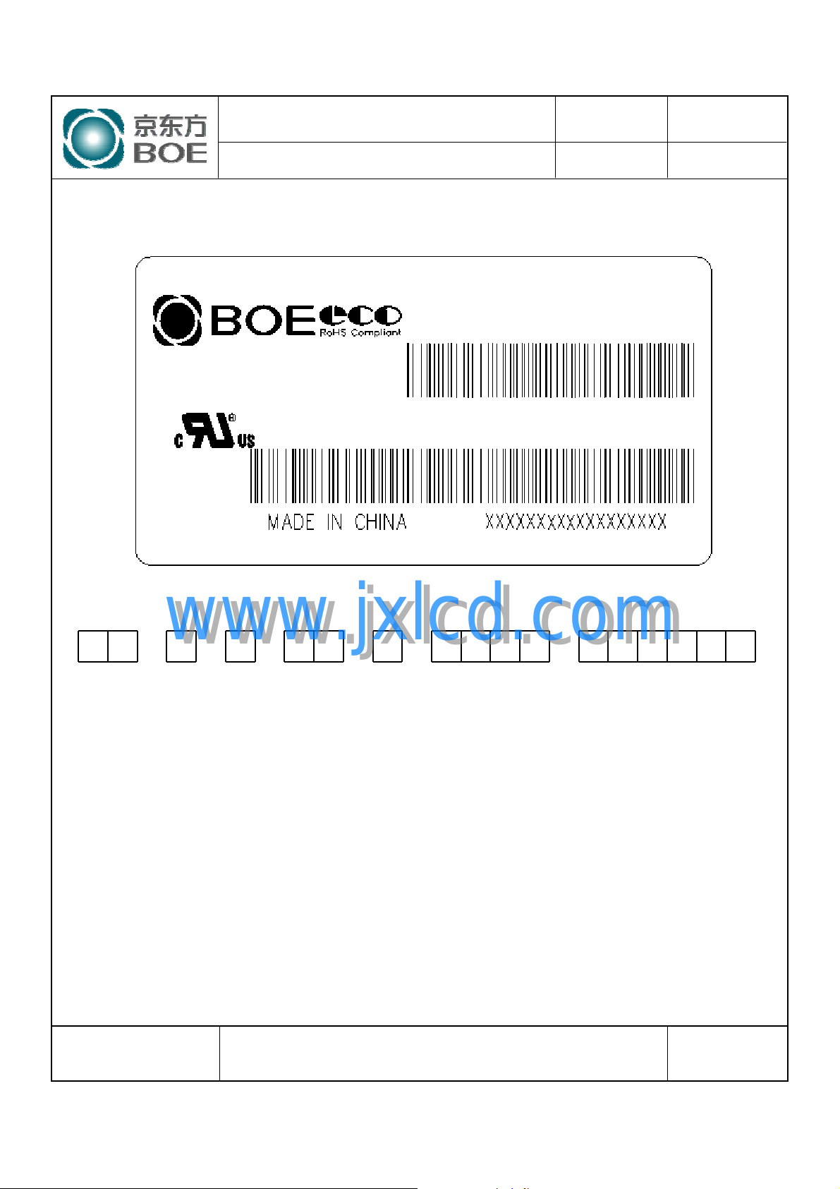
13.0 PRODUCT SERIAL NUMBER
P0
HT236F01-100
Feb. 23. 09’
1 2 3 4 5 6 7
www.jxlcd.com
XX X X XX X XXXX XXXXXX
1. Control Number
2. Rank / Grade
3. Line Classification
4. Year (2001 : 01, 2002 : 02, …)
www.jxlcd.com
5. Month (1,2,3, … , 9, X, Y, Z)
6. Internal Use
7. Serial Number
SPEC. NUMBER
S
B2006-5006-O (3/3)
SPEC. TITLE
HT236F01-100 Preliminary Product Specification_P0
PAGE
22
OF 28
A4(210 X 297)
Page 23
PRODUCT GROUP
REV
ISSUE DATE
14.0 Packing
14.1 Packing Order
TFT- LCD PRODUCT
P0
Feb. 23. 09’
www.jxlcd.com
www.jxlcd.com
SPEC. NUMBER
S
B2006-5006-O (3/3)
SPEC. TITLE
HT236F01-100 Preliminary Product Specification_P0
PAGE
23
OF 28
A4(210 X 297)
Page 24
PRODUCT GROUP
REV
ISSUE DATE
TFT- LCD PRODUCT
14.2 Packing Note
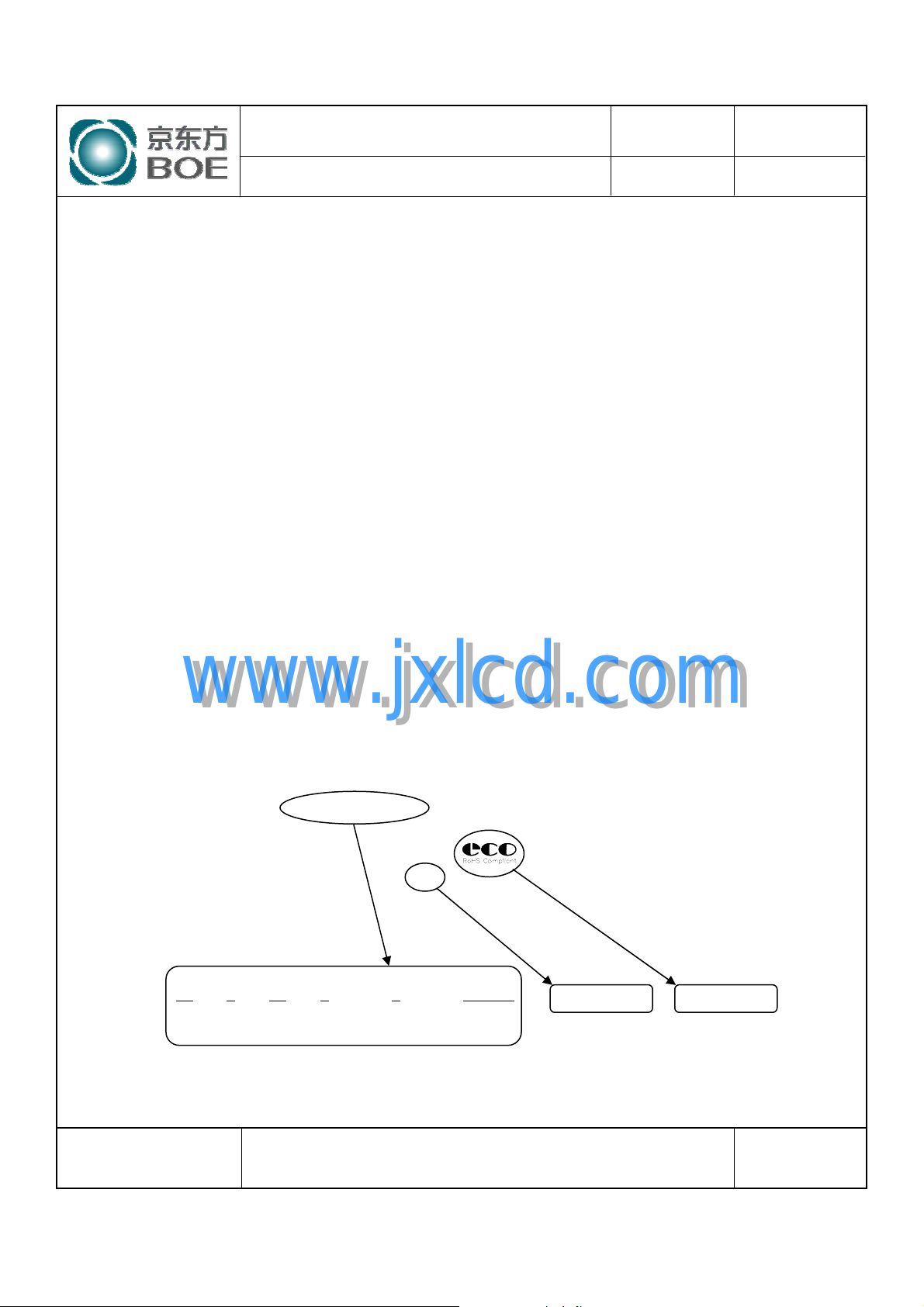
y Box Dimension : 233mm(W) × 613mm(L) × 445mm(H)
y Package Quantity in one Box : 5 pcs
14.3 Box label
y Label Size : 108 mm (L) × 56 mm (W)
y Contents
Model : HT236F01-100
Q`ty : Module Q`ty in one box
Serial No. : Box Serial No. See next page for detail description.
Date : Packing Date
P0
Feb. 23. 09’
www.jxlcd.com
www.jxlcd.com
00 0 00 0 0 000000
Type Grade Year Month ITEM-CODE Serial_no
SPEC. NUMBER
S
B2006-5006-O (3/3)
HT236F01-100
0000000000000
5940
SPEC. TITLE
HT236F01-100 Preliminary Product Specification_P0
5
200X.X.XX
Internal Use RoHS Mark
PAGE
24
OF 28
A4(210 X 297)
Page 25
PRODUCT GROUP
REV
ISSUE DATE
15.0 APPENDIX
Figure 1. Measurement Set Up
TFT- LCD PRODUCT
P0
(L = 5 0 c m )
Feb. 23. 09’
Figure 2. White Luminance and Uniformity Measurement Locations (9 points)
www.jxlcd.com
www.jxlcd.com
192 810 1728
1) 1
1) 4 1) 5
1) 7 1) 8 1) 9
1) 2 1) 3
1) 6
108
540
972
SPEC. NUMBER
S
B2006-5006-O (3/3)
SPEC. TITLE
HT236F01-100 Preliminary Product Specification_P0
PAGE
25
OF 28
A4(210 X 297)
Page 26
PRODUCT GROUP
REV
ISSUE DATE
Display data
Optical
Response
TFT- LCD PRODUCT
Figure 3. Response Time Testing
White(TFTOFF)
T
R
100%
90%
10%
0%
Figure 4. Cross Modulation Test Description
VIEW AREA VIEW AREA
Black(TFT ON)
P0
White(TFTOFF)
T
F
Time
Feb. 23. 09’
(D/4, W/4)
www.jxlcd.com
www.jxlcd.com
(D, W)
YA(7D/8,W/2)
Cross-Talk (%) = × 100
Where: YA= Initial luminance of measured area (cd/m2)
YB= Subsequent luminance of measured area (cd/m2)
The location measured will be exactly the same in both patterns
L31
YB-Y
Y
A
(3D/4, 3W/4)
(D, W)
L0
A
YB(7D/8,W/2)
SPEC. NUMBER
S
B2006-5006-O (3/3)
SPEC. TITLE
HT236F01-100 Preliminary Product Specification_P0
PAGE
26
OF 28
A4(210 X 297)
Page 27
PRODUCT GROUP
REV
ISSUE DATE
TFT- LCD PRODUCT
Figure 5. TFT-LCD Module Outline Dimensions (Front view)
P0
Feb. 23. 09’
www.jxlcd.com
www.jxlcd.com
SPEC. NUMBER
S
B2006-5006-O (3/3)
×
SPEC. TITLE
HT236F01-100 Preliminary Product Specification_P0
PAGE
27
OF 28
A4(210 X 297)
Page 28
PRODUCT GROUP
REV
ISSUE DATE
TFT- LCD PRODUCT
Figure 6. TFT-LCD Module Outline Dimensions (Rear view)
P0
Feb. 23. 09’
www.jxlcd.com
www.jxlcd.com
SPEC. NUMBER
S
B2006-5006-O (3/3)
SPEC. TITLE
HT236F01-100 Preliminary Product Specification_P0
PAGE
28
OF 28
A4(210 X 297)
 Loading...