

Body Solid EXM-1500G Owner's Manual
BODY-SOLID,Inc.
1900 S. Des Plaines Ave.
Forest Park, IL 60130 USA
Phone:(708)427-3555
Fax:(708)427-3556
www.bodysolid.com
OWNER'S MANUAL
EXM-1500G

TABLE OF CONTENTS
General Instructions………………………………..…… ..….……..2
Training Tips and Safety Information…………..………….……..3
Hardware Illustrations…………………………..……..……………4-5
Parts Illu strations……..………………………..…………..………..6
Assembly(Step 1)…………………..……………………………..7-8
Assembly(Step 2)………………..………………………………..9-10
Assembly(Step 3)…………..……………………………………..11-12
Assembly(Step 4)………………………………………………....13-14
Assembly(Step 5)………………………………………..………..15-16
Assembly(Step 6)…………………………………………..……..17-18
Assembly(Step 7)…………………………………………..……..19-20
Assembly(Step 8)…………………………………………..……..21-22
Assembly(Step 9)……………………………………………..…..23-24
Cable Adjustment s………………… …………………… ………… ...25
Inspections and Maintenance Schedule…………………..……..26
Page 1
EXM-1500G ASSEMBLY INSTRUCTIONS
EXM1500G-112003
GENERAL INSTRUCTIONS
Thank you for purchasing the Body-Solid EXM1500S Gym. At Body-solid,
our goal is to ensure customer satisfaction. If you have any questions
about these instructions or have any problems with assembly or parts for
this machine, please call our Customer Service Department at
1-800-556-3113.
Prior to assembling any Body-Solid machine, please t ake the time to read
the instructions thoroughly. Please use this manual to make sure that all
parts have been included with your shipment. When ordering
replacement parts, please refer to the part number and description of
each part from this manual. Use only Body-Solid replacement parts when
servicing any Body-Solid machine. Failure to do so may void your
warranty and could result in personal injury.
Body-Solid equipment is designed to provide the safest, smoothest and
most effective workouts possible. After you have finished assembling this
product, check all stations to ensure correct operation. If for some reason
you experience problems with any functions of this machine, do not
continue operation. First, re-check all of the assembly instructions to
locate any possible errors made during assembly. If you are not able to
correct the problem, contact our Customer Service Department
immediately at 1-800-556-3113.
TOOLS REQUIRED
•Socket Wrench
•5/16"、3/8" and 1/2" Sockets
•Crescent Wrench
•Rubber Mallet
•Tape Measure
•5/16" Allen Wrench(included)
•5/32" Allen Wrench(included)
Page 2
EXM-1500G ASSEMBLY INSTRUCTIONS
EXM1500G-112003

TRAINING TIPS AND SAFETY INFORMATION
Before starting any exercise program, it is recommended that you consult
your physician and get a complete physical examination. There is a risk
assumed by individuals who use this type of equipment. To minimize risk,
follow the rules below.
• Always consult your physician before starting any exercise program.
• Do not allow children or minors to play on or around the equipment.
• Warm up properly before engaging in any weight training regimen.
• Before using, read all the warning labels and instructions on the use of this
machine.
• Do not modify the machine in any way.
• Inspect the machine before use for any damaged, worn or missing parts. If
there is any doubt about the ability of this equipment to operate safely, do not
use the equipment until it is serviced.
• Exercise with care, performing exercises at a smooth, moderate pace. Never
perform jerky or uncoordinated movements that may result in injury.
• Never hold your breath while exercising.
• Learn how to perform the exercise correctly before using heavy weight.
Correct form is important to avoid injury and to ensure that you work the
proper muscle groups.
• It is recommended that you train with a training partner.
• Keep body and clothing clear of cables and moving parts when the machine
is in use.
• Know your limitations. If you are new to resistance training or are starting an
exercise routine after a prolonged lay-off, start slowly and build up to a more
intense routine.
Failure to follow these rules may result in serious injury. If unsure about
the proper use of the machine, consult your local Body-Solid distributor or
call the Body-Solid Customer Service department at 1-800-556-3113.
Page 3
EXM-1500G ASSEMBLY INSTRUCTIONS
EXM1500G-112003
ASSEMBLY INSTRUCTIONS
Page
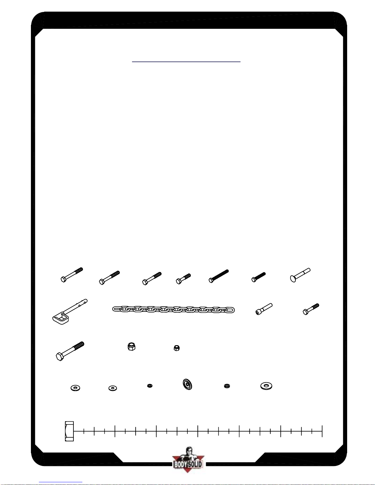
HARDWARE ILLUSTRATION
2
1
3
45
6
A2. 3/8"x3" Hex Head Bolt------------------------------------[7PCS]
A3. 3/8"x2 3/4" Hex Head Bolt-------------------------------[12PCS]
A4. 3/8"x2 1/2" Hex Head Bolt-------------------------------[4PCS]
A5.3/8"x1 3/4"Hex Head Bolt---------------------------------[9PCS]
A7.5/16"x2 3/4"Hex Head Bolt---- ----- -- - --- -- --- -- --- -- - --- [2PCS]
A8. 5/16"x1 3/4"Hex Head Bolt------------------------------[2PCS]
A9. 3/8"x2 3/4"CARRIAGE BOLT---------------------------[4PCS]
A10. SELECTOR PIN------------------------------------------[1PCS]
A11. STEEL CHAIN---------------------------------------------[1PCS]
A12. 3/8"x2" ROUND BOLT-----------------------------------[1PCS]
A13. 3/8"x2" Hex Head Bolt-----------------------------------[1PCS]
A14. 1/2"x3 3/4" Hex Head Bolt------------------------------[1PCS]
B1. 1/2" NYLON LOCK NUT----------------------------------[2PCS]
B2. 3/8" NYLON LOCK NUT--------------------------------[33PCS]
C1. 3/8"(I.D)WASHER----------------------------------------[44PCS]
C2. 5/16"(I.D)WASHER-----------------------------------------[4PCS]
C3. 5/16" SPRING WASHER---------------------------------[4PCS]
C4. 1/2" ROUND END CAP WASHER---------------------[2PCS]
C5. 3/8" SPRING WASHER-----------------------------------[1PCS]
C6.1/2" WASHER------------------------------------------------[2PCS]
EXM-1500G
EXM1500G-112003
4
A2
A3
A4
A7
A8
A9
A5
A10
A11
A12
A14
C1
C2
C3
C4
A13
B1
B2
C5
C6
ASSEMBLY INSTRUCTIONS
Page
HARDWARE ILLUSTRATION
EXM-1500G
EXM1500G-112003
5
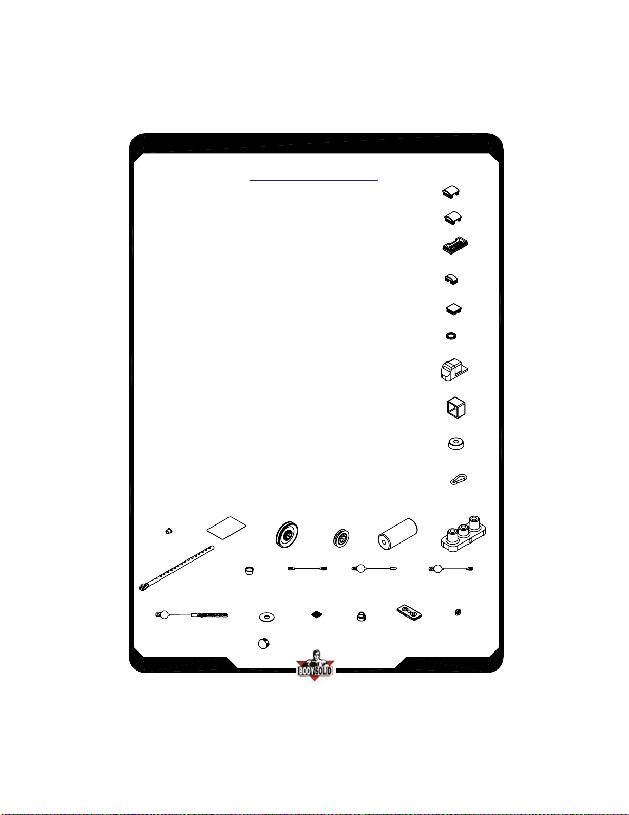
D1. 2"x2"x1.8t ROUND END CAP(9211-087)---------------[8PCS]
D2. 2"x2"x2.5t ROUND END CAP(9211-088)---------------[1PCS]
D3. 2"x4" END CAP(9211-014)---------------------------------[2PCS]
D4. 1"x2" END CAP(9211-086)---------------------------------[3PCS]
D5. 1 3/4"x1 3/4" END CAP(9211-004)-----------------------[1PCS]
D6.
n1" CHROME END CAP(8341-033)---------------------[6PCS]
D7. 2"x2" FOOT CAP(9211-024)-------------------------------[4PCS]
D8. 2"x2" ROUBBER CAP(9310-020)-------------------------[1PCS]
D9.
n2 1/2" RUBBER DOUNT(9310-010)-------------------[2PCS]
D10.
n8mm SPRING SNAP LINK(8810-001)---------------[5PCS]
D11.
n16 STEEL BUSHING(9211-041)----------------------[12PCS]
D13. 95X140mm NO SLIP TAPE(9310-035)----------------[2PCS]
D14.
n110(4 1/4")PULLEY(9213-002C)----------------------[15PCS]
D15.
n3"PULLEY(9213-006)------------------------------------[1PCS]
D16.
n3 1/2x8" FOAM ROLLER(9161-007)-----------------[6PCS]
D17. TOP PLATE(8400-005)------------------------------------[1PCS]
D18. WEIGHT SELECTOR BAR(8210-052A)---------------[1PCS]
D19. 1/2" BOLT CAP----------------------------------------------[2PCS]
D20. 1440mm STEEL CABLE-----------------------------------[1PCS]
D21. 3235mm STEEL CABLE-----------------------------------[1PCS]
D22. 3050mm STEEL CABLE----------------------------------[1PCS]
D23. 2210mm STEEL CABLE-----------------------------------[1PCS]
D25.
n3" NYLON WASHER(9214-008)----------------------[8PCS]
D26. 38X4tx38 RUBBER PAD(9310-001)--------------------[1PCS]
D28.
n3/4 SHAFT COOLAR(9211-046)----------------------[2PCS]
D29. 10LB SELECTOR PLATE---------------------------------[15PCS]
D30.
n1" ROUND END CAP(9260-021)------------ -- --- -- --[6PC S]
D31.
n50 ROUND END CAP(9211-080)---------------------[2PCS]
D1
D2
D3
D4
D5
D6
D7
D8
D9
D10
D11
D13
D14
D15
D16
D17
D18
D21
D22
D20
D19
D23
D25
D26
D28
D29
D30
D31
ASSEMBLY INSTRUCTIONS
Page
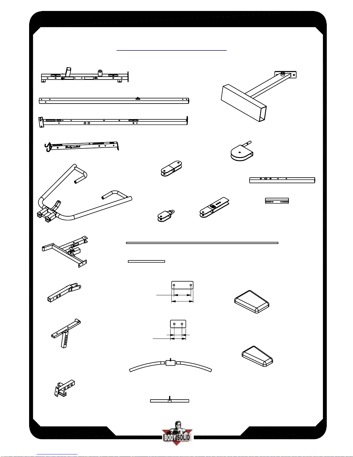
PARTS ILLUSTRATION SHEET
EXM-1500G
EXM1500G-112003
6
A.MAIN BASH FRAME[1PCS]
B.REAR BASE FRAME[1PCS]
C.ANGLED SUPPORT PILLAR[1PCS]
D.TOP FRAME[1PCS]
E.BENCH PRESS FRAME[1PCS]
F.SEAT/EXTEMSION FRAME[1PCS]
G.LEG FRAME[1PCS]
H.SEAT FRAME[1PCS]
I.TOP WEIGHT
STACK FRAME[1PCS]
J.FOOT BRACE
K.LOW
PULLEYBRACKET(1PCS]
L.WELDED
DOUBLE
BRACKET[1PCS]
M.SINGLE
PULLEY
HOOK[1PCS]
N.WELDED
"ADJUSTABLE"
DOUBLE
BRACKET[1PCS]
O.REAR BASE FRAME[1PCS]
P.FRONT BASE FRAME[1PCS]
Q.CHROME GUIDE ROD[2PCS]
R.FOAM ROLLER BAR[3PCS]
S.2"x5 1/2" PLATE[2PCS]
8312-090
110
140
T.2"x4" PLATE[1PCS]
8312-049
50
100
U.LAT BAR[1PCS]
20LB1100D
V.LOW ROW BAR[1PCS]
20LB500C
W.SEAT PAD
9123-010
X.BACK PAD
9113-006
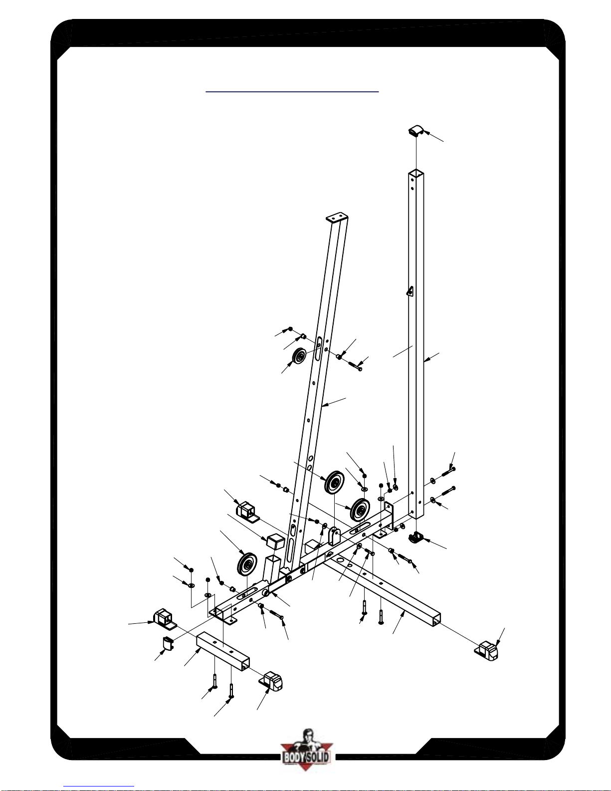
ASSEMBLY- STEP 1
**Note:Do Not fully tighten frame bolts and nuts until after completing Step 3
**Note
:
Do Not fully tighten pulley bolts and nuts until after cable routing
The following Parts and Hardware will be needed to complete Step 1
Parts Description Hardware Description
Qty
Part Part Description Qty Part Part Description
1 A Main Base Frame 2 A2
3/8"×3" hex head bolt
1 B Vertical Support Pillar 5 A3
3/8"×2 3/4" hex head bolt
1 C Angled Support Pillar 1 A5
3/8"×1 3/4" hex head bolt
1 O Rear Base Frame 4 A9
3/8"×2 ¾" carriage bolt
1 P Front Base Frame 12 B2
3/8" nylon lock nut
14 C1
3/8" I.D. washer
2 D1 2”x2”x1.8t rounf end cap
1 D2
2"×2"×2.5t round end cap
4 D7
2"×2" foot cap
1 D8
2"×2" rubber cap
6 D11 phi 16 nylon bushing
3 D14
4
½" pulley
1 D15
3
" pulley
Step by Step
1. Attach 4 (D7) - Foot Caps to (P) Front Base Frame and (O) Rear Base Frame
2. Attach (A) - Main Base Frame to (O) - Rear Base Frame
3. Attach (A) - Main Base Frame to (P) - Front Base Frame
4. Attach (C) - Angled Support Pillar to (A) - Main Base Frame
5. Attach (B) - Vertical Support Pillar to (A) - Main Base Frame
6. Attach 3 (D14) and 1 (D15) pulleys to frame as shown
(Note:DO NOT fully tighten pulley bolts and nuts until after cable routing)
Page 7
EXM-1500G ASSEMBLY INSTRUCTIONS
EXM1500G-112003
ASSEMBLY INSTRUCTIONS
Page
ASSEMBLY STEP
1
P
EXM1500G-112003
8
EXM-1500G
D7
C1x2
B2x2
B2
D14
D8
D7
D11x2
A3
D15
D11
B2
D11
A3
C
B
D14
B2x2
C1x2
B2x2
C1x2
A3x2
C1x2
D11x2
A3
B2
C1
B2
A9x2
C1
A5
O
D7
A9
A9
D7
A
D14
D2
D1
D1
O
 Loading...