

Bock Water Heaters 72E, 361E, 541E Installation Operation & Maintenance
TO THE INSTALLER:
Please attach these in struc tions next to the
water heater.
TO THE CONSUMER:
Read these and all
com po nent in struc tions. Please keep for
fu ture reference.
Bock Water Heaters, Inc.
110 S. Dickinson St. • P.O. Box 8632
Madison, WI 53708-8632
Phone: 608/257-2225
Fax: 608/257-5304
www.bockwaterheaters.com
INSTALLATION, OPERATION
& MAINTENANCE IN STRUC TIONS
Waranty, registration card
OIL-FIRED WATER HEATERS
& parts list in clud ed.
WARNING: Improper installation, adjustment, al ter ation,
ser vice or main te nance can cause se ri ous in ju ry or
er ty dam age. Refer to this man u al. For as sis tance
prop
or ad di tion al in for ma tion, con sult a qualified in stall er or
ser vice agen cy.
WARNING: If the information in these instructions is not
fol lowed exactly, fire or explosion may result and can
cause prop er ty damage, personal in ju ry or death.
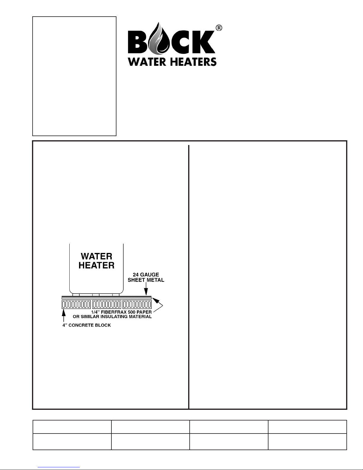
DO NOT INSTALL THE WATER HEATER ON COM BUS TI BLE FLOORING.
codes. In the ab sence of local codes, refer to NFPA 31,
CSA B139,
con cern ing prop er floor ing ma te ri als.
Minimum clearance to combustible con struc tion is:
SIDES 6"; BACK 6"; FRONT 24". The in stal la tion of this
water heater must con form with local codes and or di nanc es. In the absence of local codes, the installation
must com ply with the Na tion al Fire Pro tec tion As so ci a tion (NFPA 31) Code or CSA B139.
WARNING: The recommended temperature for nor mal
res i den tial use is 120oF. The dial on the aquastat does not
always re flect the outcoming water temperature, which
could oc ca sion al ly ex ceed 120oF. The vari a tion in outcoming tem per a ture could be based on factors in clud ing
Install in ac cor dance with all local
or con tact Bock Wa ter Heat ers with ques tions
72E • 361E • 541E
but not lim it ed to usage pat terns and type of in stal la tion.
Test your water at the tap nearest to the wa ter heat er.
WARNING: Hotter water increases the risk of scald in ju ry. Be fore changing the temperature set ting, read the
in struc tion manual. Tem per a tures at which injury oc curs
vary with the in di vid u al’s age and length of ex po sure.
The slower reaction times of children, elderly and phys -
cal ly or mentally impaired persons in creas es the
i
scald ing hazard to them. It is rec om mend ed low er wa ter
tem per a tures be used where these sit u a tions exist.
To lower water temperature use point-of-use tem per a ture limiting devices.
WARNING: Flammable vapors may be drawn to this
wa ter heat er from other areas of the struc ture by air cur rents. Do not store or use any flam ma ble liquids in
vi cin i ty of this heater.
the
WARNING: Never burn garbage or paper in the water
heater and never leave paper or rags around it.
WARNING: Water heater blankets may restrict air flow
to the heat er and cause fire, asphyxiation, per son al in ju ry or death.
Note: Heat loss should be considered when determining
correct size of water heater.
WARNING: Hydrogen gas can be produced in a hot
water system that has not been used for an extended
iod–gen er al ly, two weeks or longer. To prevent possi-
per
ble injury under this situation, we recommend that a hot
water faucet be wide open for several minutes before
you use ANY electrical appliance that is con nect ed to
the hot water system. If hydrogen is present, an unusual
sound – such as air escaping – will come from the open
faucet as the hot water begins to flow. Hydrogen
extremely flammable – there must be no open flame
near this open faucet.
gas is
Installer Contact Information
Installed By Purchased From Address Phone#
23400
Rev 10 3/18
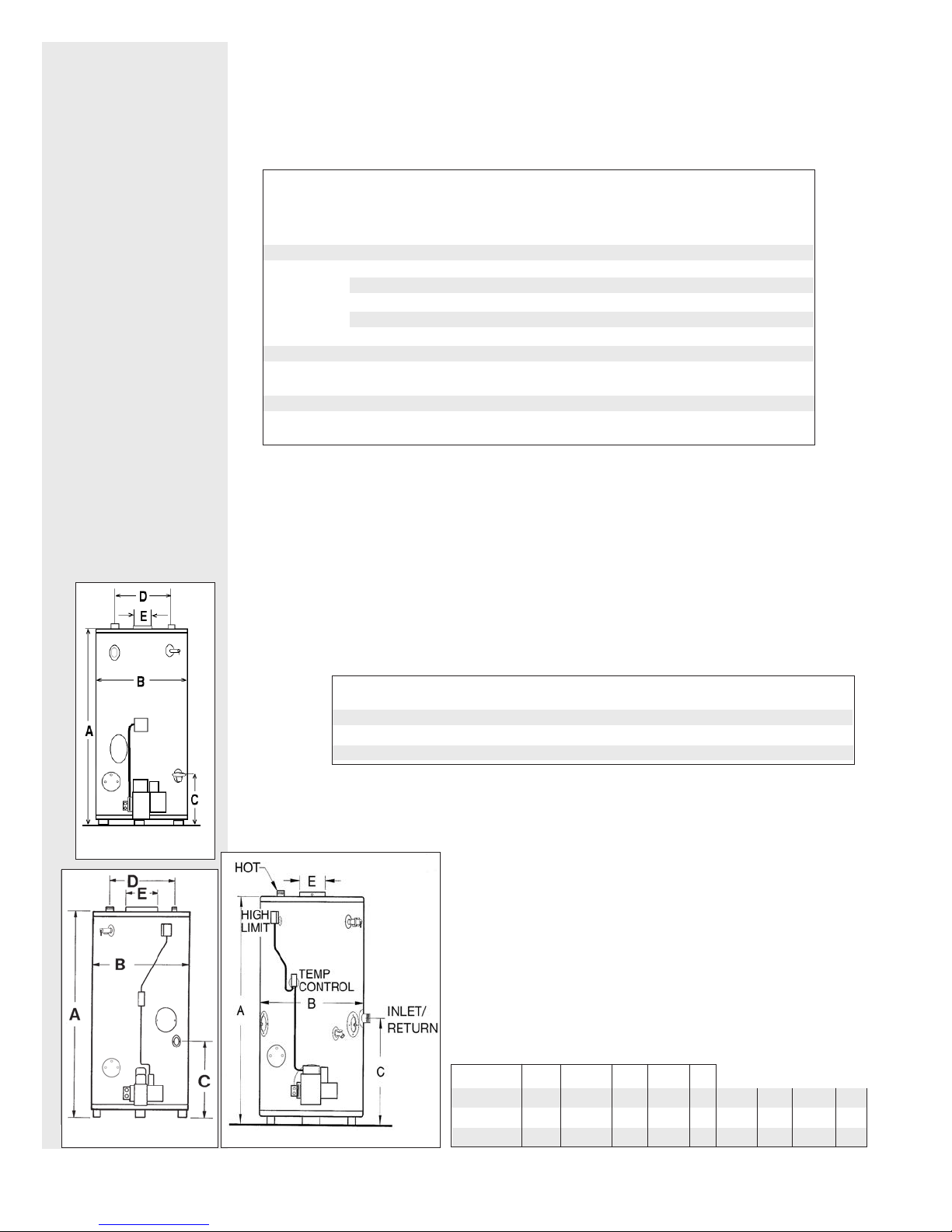
PERFORMANCE SPEC I FI CA TIONS
AND ROUGHING-IN DI MEN SIONS
CAUTION:
The rec om mend ed
water tem per a ture
setting for normal
res i den tial use is
O
F.
120
MODEL/OEM # NOZZLE PRESSURE
72E CARLIN EZ-2HP/9833222J72E 1.25X70
WAYNE MSR/371-019B 1.50X80OB 100 PSI
RIELLO R35.5/C8512221 1.25X60
RIELLO 40F10/ 1.25X60OB 150 PSI
BECKETT AF / BK8-160 or BK8-180 1.50X80OB 100 PSI
361E CARLIN 201CRD/98285000B361E 2.50X70
WAYNE EH/371-026 3.00X80OA 100 PSI
541E CARLIN 201CRD/98285000B541E 4.00X70
WAYNE EH/371-028 4.50X80OB 100 PSI
Leave ample room for servicing when the wa ter heater is in stalled – do not block ac cess to the burner, inspection door,
handholes or con trols. Leave room to pipe the unit and connect
the fuel and elec tric i ty.
BURNER SPECIFICATIONS
O
B 150 PSI
O
B 150 PSI
O
B 150 PSI
O
B 130 PSI
72E
361E
– 2 –
SIZES AND CAPACITIES
(shipping weights are complete assembly, including burners and controls)
MODEL
72E 67 GAL. 199,000 1.50 GPH 120V 60HZ 1/7 HP 550 LBS. ––
361E 91 GAL. 415,000 3.00 GPH 120V 60HZ 1/4 HP 1105 LBS. 1125 LBS.
541E 83 GAL. 623,000 4.50 GPH 120V 60HZ 1/4 HP 1330 LBS. 1340 LBS.
STORAGE
CAPACITY
BTUH
INPUT
FIRING
RATE
MODEL A B C D E
72E
58” 28” 20” 16” 8” 1
361E
67” 31
541E
541E
66” 34” 30
STANDARD
VOLTAGE
1
/
2
” 26” 23” 9” 2”* 1” 3/4” 2”
* Nipple not furnished ** Under drain valve
MOTOR
1
/
2
” NA 10” 2”* 2”* 3/4” 2”
SHIPPING WEIGHT
STANDARD ASME
HOT
OUTLET *
1
1
/
2
”* 1
on 72E only
COLD
INLET
/
2
” 3/4” 1
DRAIN
ALT INLET/
RETURN **
1
/
2
”
COMBUSTION &
VENTILATION AIR
NOTE: All ducts
must have the same
cross sectional area
as the free area of
each opening to
which they connect.
The minimum side
dimension of a rec tan gu lar duct must
be no smaller than
three (3) inches.
Caution:
Operation
of exhaust fans, ventilating sys tems,
power burn ers, in duced draft systems,
clothes dryers, or
fire places may create con di tions that
require special
attention to avoid
un sat is fac to ry op er a tion of installed
equipment.
WATER PIPING
Care must be taken to insure an adequate air supply for the wa ter heater.
A. Install equipment only where the water heater will have sat is fac tory com bus tion, proper vent ing,
and the maintenance of temperature at safe limits all around the unit under normal operating conditions. Free circulation of air around the water heater is essential. If the air supply is inadequate,
introduce outside ai
tional air (see NFPA 31 for air requirements).
ddition to air needed for combustion, air may be required for draft control; cooling off; con trol ling
B. In a
dew point; heating; drying; oxi da tion or dilution; safety ex haust; odor control; and compressors.
C. Make sure air around the water heater is adequate for personnel comfort and working conditions.
. Check for proper draft. Place a draft gauge in the chimney above the draft diverter. Drafts should
D
be at least -0.02" W. C. and less than -0.05” W.C. while the water heater is in operation.
Unconfined space: No additional combustion and ven ti la tion air is required if the volume of the
space is greater than 50 cubic feet per 1,000 BTUH of the combined total input of all equipment in -
in that space. Rooms leading directly to the space through openings which cannot be closed
stalled
are considered part of the unconfined space.
Confined space: When the unit will be installed in a space with a volume of less than 50 cubic feet
per 1,000 BTUH, the space must be vented at the floor for combustion air and at the ceiling for ven ti la tion. This air can be supplied from either inside or outside of the building as conditions allow (refer
NFPA 31 or local codes).
to
A. Inside air supply: Provide two permanent openings; one within 12" of the top of the enclosure and
one within 12" of the bottom, leading directly to room(s) of sufficient vol ume so that the combined
volume of all the space meets the criteria for unconfined space. Each opening requires a minimum free area of one (1) square inch (two square inches total) per 1,000 BTUH of the combined
total input of all equip ment installed in the enclosure, but not less than 100 square inches.
B. Outside
and one within 12" of the bottom. These openings must lead directly to crawl and attic spaces
leading directly to the outside of the building.
Louvers and grilles: In calculating the “free” area in Equip -
ment Located in Confined Spaces, consider the blocking
effects of louvers, grilles, or screens pro tect ing openings. The
screens cannot be smaller than one (1) inch of mesh. If the “free”
area of a louver or grille is known, it should be used in calculat-
the size opening required to provide the “free” area specified.
ing
If the design and “free” area is not known, assume wood louvers
have 20% to 25% “free” area, and metal louvers and grilles 60%
to 75%. Fix louvers and grilles in the open position or interlock
with the equipment so they are opening automatically during
equipment operation.
Models 72E and 361E have dip tubes. When using sweat fit tings,
not apply heat to the nipples. Pipe hot and cold lines with a
do
union and valve on each line.
If backflow preventers and pressure regulators are installed or if
the heater is installed in a closed system, allow for water expansion by installing either a thermal expansion valve or an ex pan sion tank in the system. Contact the
local water sup pli er or plumbing in spec tor to correct the situation.
Piping
used in space heating systems and connected to the service water heater shall be suitable for
use with potable water. Toxic chemicals such as those used for boiler treatment shall not be introduced into the potable water system that is also used for space heating. A water heater that will
used to supply domestic hot water shall not be connected to the heating system or connected
be
with components previously used with a non-potable water heating appliance.
air supply: Provide two permanent openings; one within 12" of the top of the enclosure
Leading directly to outside or through vertical ducts: Each opening (top and bottom)
1.
requires a minimum free area of one (1) square inch (two square inches total) per 4,000 BTUH
of the combined total input of all equipment in stalled in the enclosure.
2. Leading to the outside through horizontal ducts:
Each opening (top and bottom) requires a minimum free
area of one (1) square inch (two square inches total) per
BTUH of the combined total input of all equipment
2,000
installed in the enclosure.
components and connection materials (eg, solder, solvent cement, thread joint compounds)
r. Any temperature above 90°F around the heater indicates a need for addi-
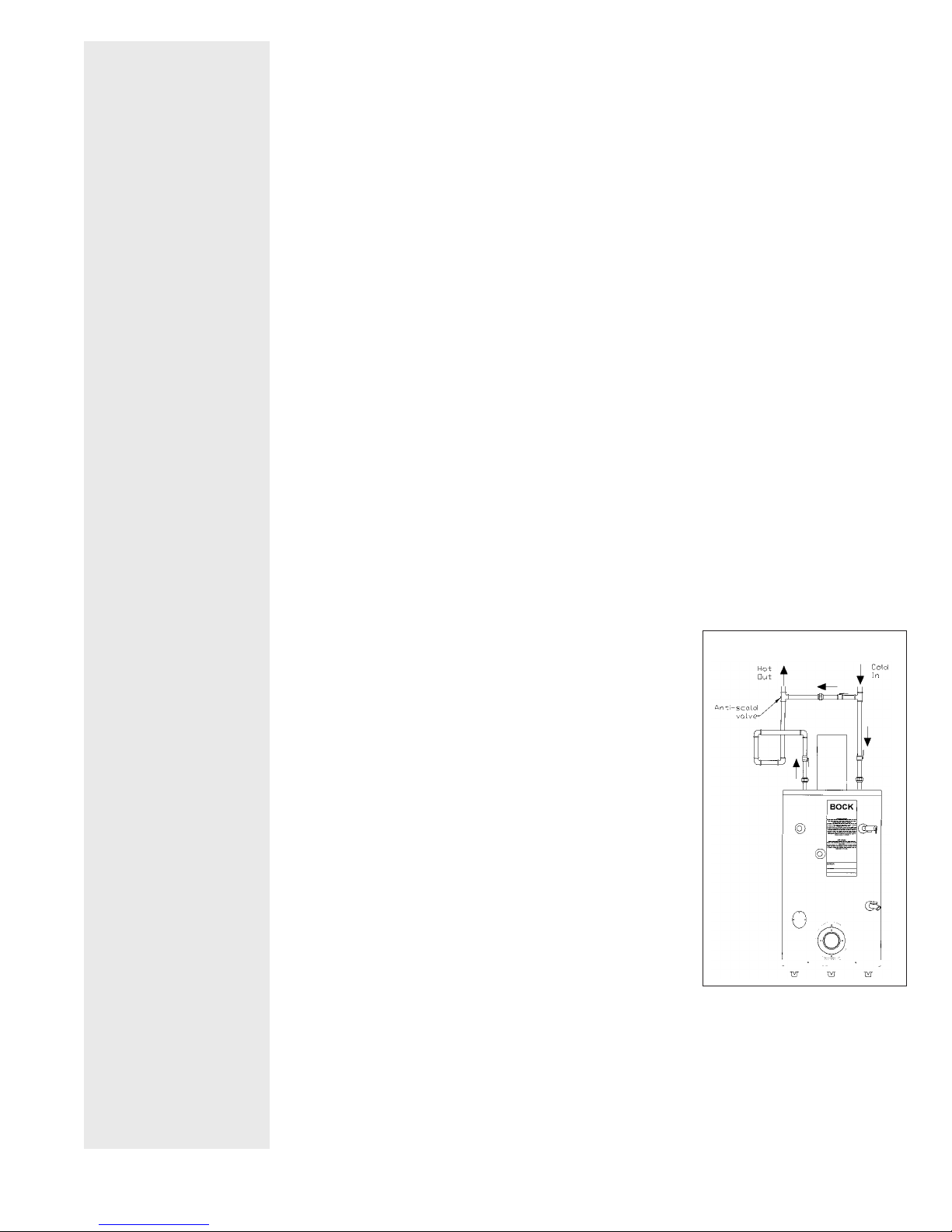
FIGURE 1
– 3 –
A thermostatically controlled anti-scald valve meeting requirements of CSA B125 or ASSE 1016 or
1017 should be used to temper the domestic hot water supply to fixtures to 49OC (120OF). See
Figure1 for proper installation of antiscald valve.
T&P RELIEF VALVE
OIL SUPPLY
ATTACH BURNER
& OIL LINES
FIGURE 4
Install a water soft en er if the heater is
being used in a hard
water area (wa ter
hardness of more
than sev en grains).
– 4 –
The temperature and pressure (T&P) relief valve has been factory installed.
To prevent water damage when relief occurs, install a discharge line from the relief valve outlet to a
for water disposal. Do not install a reducing coupling or other restriction in the dis charge line.
place
Arrange the line to allow com plete drainage of both the relief valve and the discharge line. If the T&P
relief valve discharges periodically, service to the water system is required.
Do not place a shut-off valve between the relief valve and the water heater.
Check hand holes for tightness.
The oil tank location and installation, tank size, piping supply and burners, including all fuel handling components must comply with the applicable codes for oil-burning equipment (CAN/CSA-B139 or NFPA 31,
local codes and regulations).
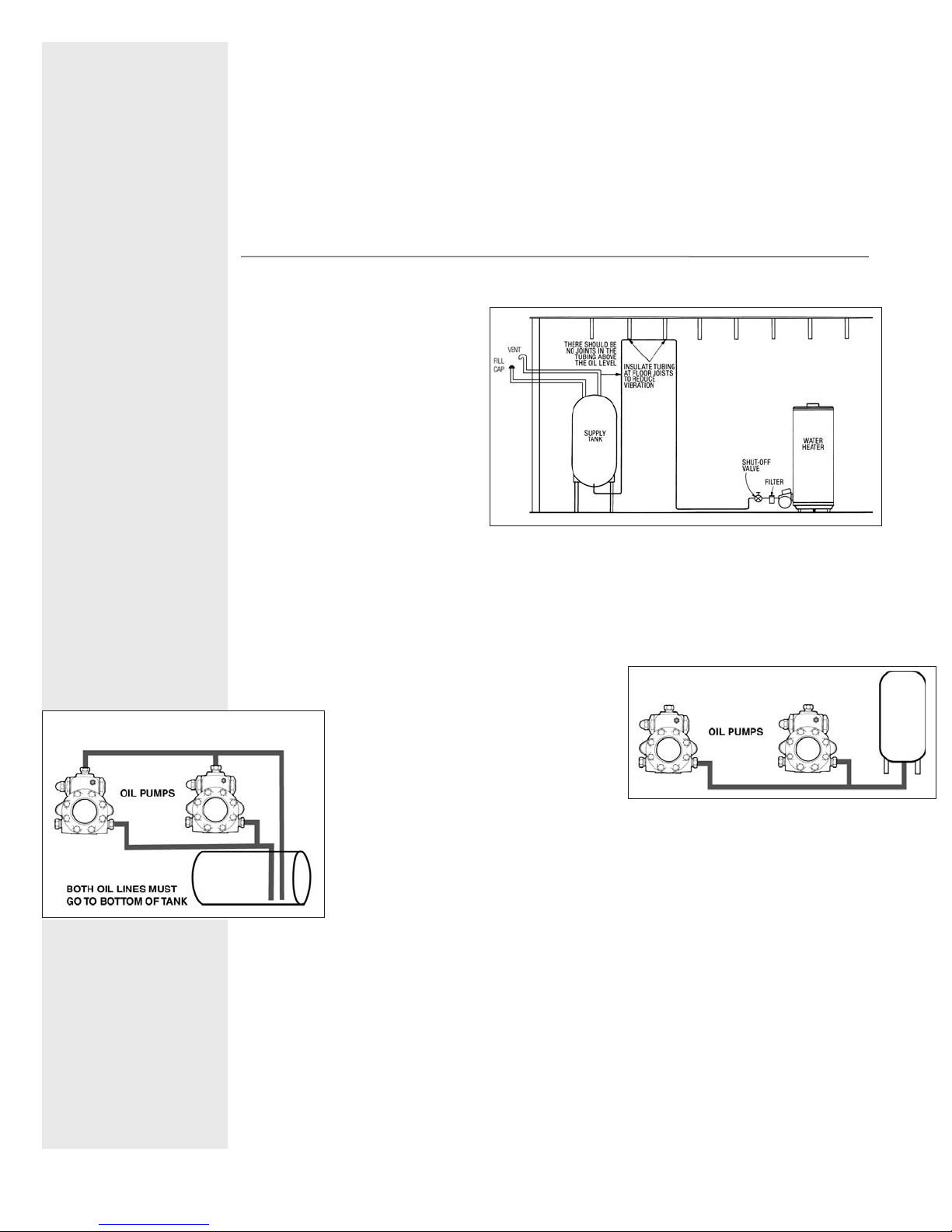
The oil supply tank must be installed
with fill and vent lines of adequate
capacity. See Figure 2 for installation
diagram.
The water heater requires fuel (#1 or
#2 heating oil), electricity and
should be closed to the chimney
and water supply. Do not use gasoline, crankcase drainings, or any oil
containing gasoline. Never burn
garbage or paper in the unit, and
never leave paper or rags around it.
1. The op er at ing thermostat and high
limit are packed with the burner.
Mount the burner with bolts pro vid ed. Burners are shipped with all settings at the approximate start
Check in side the com bus tion cham ber to verify that the burn er tube is not ob struct ed or pro-
point.
truding into the cham ber. Swing back the hinged trans form er and rotate the blower wheel by hand a
few turns to loosen the pump seal.
2. Bock rec om mends a two-pipe (suction and return) system for these heat ers. Use 1/2" O.D. soft cop per tub ing (5/8” O.D. soft copper on Sun Tec H pumps) and
install a by pass plug on two-pipe system. (See instructions
packed with pump.) Note: Do not install a bypass plug if us ing a gravity (one-pipe) system (See Fig ure 3.) For mul ti ple
heater in stal la tions, run a separate suction
and re turn line for each heater (See Figure 4.)
he com bined lift and hor i zon tal run ex ceeds
If t
100’, install a boost er pump as close to the
supply tank as possible.
Booster
Tec Hy drau lics, Rockford, Ill.
3. Return lines must be the same diameter as suction lines and extend close to the bottom of storage tank but stop slightly above suc tion lines. Use a minimum of fittings and
make bends in tubing with as large a radius as possible. Always use flared fittings, not
com pres sion fittings. If pipe is used instead of tubing, do not connect the burner to the
pipe
4. When installing an oil water heater with an existing oil tank and lines, check existing line sizes and
compare to instructions shipped with the pump to see if they are ad e quate. Do not use ex ist ing lines
if they are smaller than 1/2" O.D. tube on Models 361E and 541E. Pro ceed as fol lows:
If existing oil heater has a one-pipe sys tem, tee into the sys tem to furnish oil to the heater.
A.
B. If the existing oil heater has a two-pipe system, check wheth er the return line ex tends to the bottom of the tank. It may be preferable to change the existing oil heat er to a one-pipe sys tem and
change the re turn line to the suction line for the heat er.
C. If (B) is not applic
the heater. Both suc tion and return lines must extend to the bottom of the tank, but if the tubing is too
small and a two-stage pump is on the ex ist ing oil appliance, the water heater pump may be starved
for oil.
D. If return lines do not extend to the bottom of the tank, use check valves on each suction line as close
pumps may be obtained from Sun
– use copper tubing and form a coil be fore at tach ing tubing to burner.
able, tee into the ex ist ing suction line and the existing return line to supply oil to
FIGURE 3
FIGURE 2
GRAVITY SYS TEM
 Loading...