


200
TO THE CONSUMER:
Read these and all
component instructions. Please keep for
future reference.
TO THE INSTALLER:
Please attach these
instructions next to
the water heater.
INSTALLATION, OPERATION & MAINTENANCE INSTRUCTIONS
GAS, OIL & DUAL FUEL WATER HEATERS
150 • 200 • 250
Warranty and registration card included
WARNING: Improper installation, adjustment, alteration,
service or maintenance can cause serious injury or property damage. Refer to this manual. For assistance or additional information, consult a qualified installer or service
agency.
WARNING: If the information in these instructions is not
followed exactly, fire or explosion may result and can cause
property damage, personal injury or death.
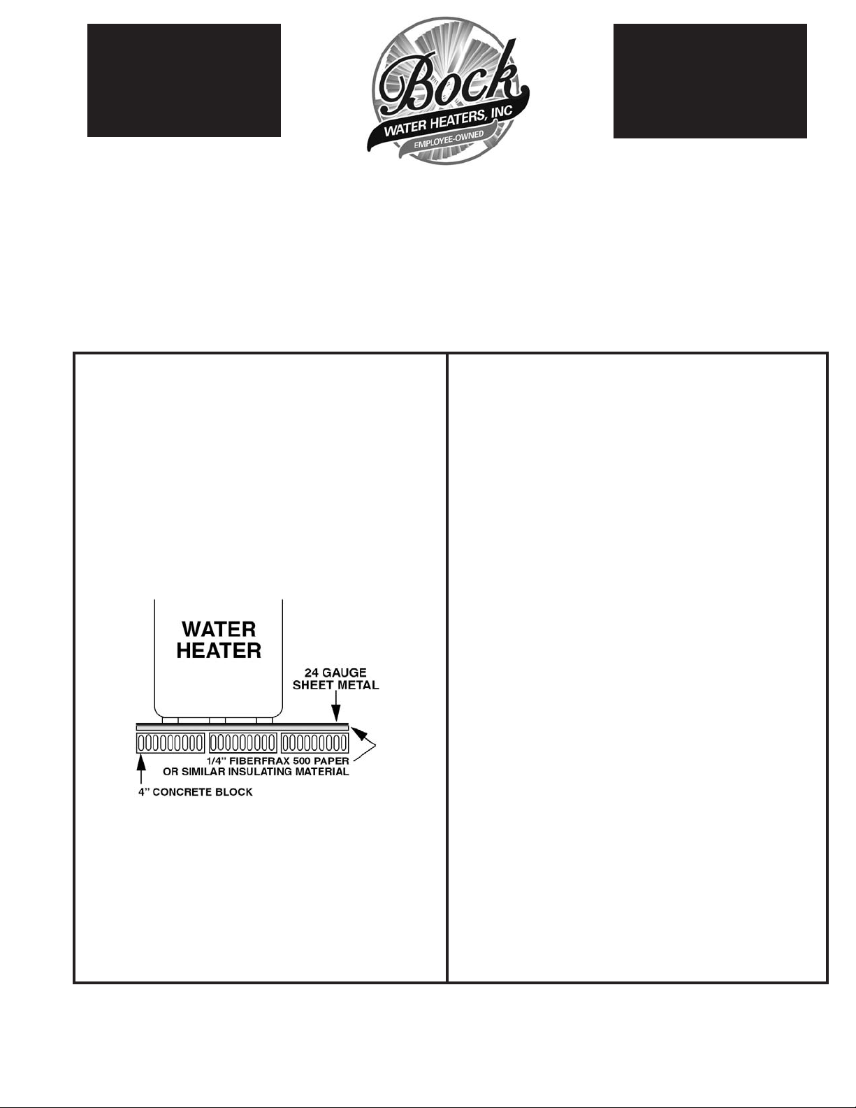
DO NOT INSTA LL THE WATER HEATER ON COMBUSTIBLE FLOORING. Install in accordance with all local
codes. In the absence of local codes, refer to NFPA 31 or
ANSI Z21.10.1, or contact Bock Water Heaters with
questions concerning proper flooring materials.
Minimum clearance to combustible construction is:
SIDES 6”; BACK 6”; FRONT 24”. The installation of
this water heater must conform with local codes and
ordinances. In the absence of local codes, the installation must comply with the National Fire Protection
Association (NFPA 31) Code.
WARNING: The recommended temperature for normal residential use is 120°F. The dial on the aquastat does not
always reflect the outcoming water temperature, which
could occasionally exceed 120°F. The variation in outcoming temperature could be based on factors including but not
limited to usage patterns and type of installation. Test your
water at the tap nearest to the water heater.
WARNING: Hotter water increases the risk of scald injury.
Before changing the temperature setting, read the instruction manual. Temperatures at which injury occurs vary with
the individual’s age and length of exposure.
The slower reaction times of children, elderly and physically
or mentally impaired persons increases the scalding hazard
to them. It is recommended lower water temperatures be
used where these situations exist.
To lower water temperature use point-of-use temperature limiting devices.
WARNING: Flammable vapors may be drawn to this water
heater from other areas of the structure by air currents. Do
not store or use any flammable liquids in the vicinity of
this heater.
WARNING: Water heater blankets may restrict air flow to
the heater and cause fire, asphyxiation, personal injury or
death.
WARNING: Hydrogen gas can be produced in a hot water
system that had not been used for an extended period-generally, two weeks or longer. To prevent possible injury
under this situation, we recommend that a hot water faucet
be wide open for several minutes before you use ANY electrical appliance that is connected to the hot water system.
If hydrogen is present, an unusual sound – such as air
escaping – will come from the open faucet as the hot water
begins to flow. Hydrogen gas is extremely flammable –
there must be no open flame near this open faucet.
Bock Water Heaters, Inc.
110 S. Dickinson St. • P.O. Box 8632 • Madison, WI 53708-8632
Phone: 608/257-2225 • Fax: 608/257-5304 • www.bockwaterheaters.com

Bock Multi- 150-400 150-600 150-800 200-450 200-650 200-850 200-1150 250-800 250-1000 250-1250 250-1500
Flue Series
Nominal Storage 176 gal. 168 gal. 160 gal. 221 gal. 212 gal. 204 gal. 192 gal. 273 gal. 260 gal. 251 gal. 242 gal.
Stack Size, in. 8 in. 8 in. 10 in. 8 in. 8 in. 10 in. 12 in. 10 in. 12 in. 14 in. 14 in.
Turboflues, Qt. 35 735 7107101214
Anode Rods, Qt. 4 4 6 4 4 6 10 6 8 10 11
Bock Oil 150E-400 150E-600 150E-800 200E-450 200E-650 200E-850 200E-1150 250E-800 250E-1000 250E-1250 250E-1500
Fired Model
Max. Fire Rate 3.0 gph 4.5 gph 6.0 gph 3.2 gph 4.6 gph 6.1 gph 8.2 gph 6.0 gph 7.1 gph 9.0gph 11.0 gph
Btu/hr input 400000 600000 800000 450000 650000 850000 1150000 800000 1000000 “1,250,000” 1500000
Burner Make Wayne Wayne Wayne Wayne Wayne Wayne Wayne Wayne Wayne Wayne PowerFlame
Model EH EH EH EH EH EH FH EH FH FH C2-OAS
Nozzle 3.0 x 80A 4.5 x 80B 5.5 x 80A 3.0 x 80B 4.5 x 80B 6.0 x 70B 2-4.0 x 80B 6.0 x 70B 2-3.5 x 80B 2-4.5 x 80B 6.00x70B*
OEM Number 371-026B 371-028 193-020 371-028 371-028 193-020 193-022 193-020 193-022 193-022
Burner Make Carlin Carlin Carlin Carlin Carlin Carlin Carlin
Model 201 CRD 301 CRD 301 CRD 201 CRD 301 CRD 301 CRD 301 CRD
Nozzle 2.5 x 70B* 4.0 x 80B* 5.0 x 80A or 70W* 2.5 x 70B* 4.0 x 80B* 5.0 x 80A or 70W* 5.0 x 80A or 70W*
OEM Number 9828500B361E 9859400B 9859400B 9828500B361E 9859400B 9859400B 9859400B
Bock Dual 150DF-400 150DF-600 150DF-800 200DF-450 200DF-650 200DF-850 200DF-1150 250DF-800 250DF-1000 250DF-1250 250DF-1500
Fuel Model
Max. Fire Rate 3.0 gph 4.5 gph 6.0 gph 3.2 gph 4.6 gph 6.1 gph 8.2 gph 6.0 gph 7.1 gph 9.0 gph 11.0 gph
Btu/hr input 400000 600000 800000 450000 650000 850000 1150000 800000 1000000 1,250,000 1500000
Burner Make Power Flame Power Flame Power Flame Power Flame Power Flame Power Flame Power Flame Power Flame Power Flame Power Flame Power Flame
Model C1-GO-10 C1-GO-10 C1-GO-10 C1-GO-10 C1-GO-10 C1-GO-10 C1-GO-12 C1-GO-10 C1-GO-12 C1-GO-12 C2-GO-15
Nozzle 1.65x70B* 2.50x70B* 3.25x70B* 1.75x80B* 2.50x70B* 3.5x70B* 4.50x70B* 3.25x70B* 4.0x70B* 5.00x70B* 6.00x70B*
Bock Power 150G-400 150G-600 150G-800 200G-450 200G-650 200G-850 200G-1150* 250G-800 250G-1000 250G-1250* 250G-1500
Gas Model
Btu/hr input 400000 600000 800000 450000 650000 850000 1150000 800000 1000000 “1,250,000” 1500000
Burner Make Power Flame Power Flame Power Flame Power Flame Power Flame Power Flame Power Flame Power Flame Power Flame Power Flame Power Flame
Model J15A-10 J15A-10 J30A-10 J15A-10 J15A-10 J30A-10 J30A-12 J30A-10 J30A-10 J30A-12 C2-G-15
SPECIFICATIONS
Leave ample room for servicing when the water heater
is installed – do not block access to the burner, inspection door, handholes or controls. Leave room to pipe
the unit and connect the fuel and electricity.
Burner Controls:
Burner Primary Control Detector
Wayne EH R8184G 1294 C554A
PF C2-0AS RM7895C 1012 C7072A
PF C1-GO-10,12,15 RM7895C 1012 C7072A
CARLIN 201CCRD, 301CRD P/N 4020002 C1440700K
Aquastats: High Limit Honeywell Model L4080 & Averaging Control Model L8100C.
Flue Tubes:
Flue tubes constructed of steel minimum, 1/8 in. thick, 6 in. OD by 35 in. long, and
provided with fins welded in a spiral pattern.
Model
Number of Flues
150-400 3
200-450 3
150-600 5
200-650 5
150-800 7
200-850 7
200-1150 10
250-1250 12
250-1500 14
BURNER SPECIFICATIONS

Improper installation, adjustment, alteration, service or maintenance can cause serious injury or
property damage. Refer to this manual. For assistance or additional information, consult a qualified
installer or service agency.
If the information in these instructions is not followed exactly, fire or explosion may result and can
cause property damage, personal injury or death.
Do not install on combustible flooring. Minimum clearance to combustible construction is: SIDES: 6”;
BACK: 6”; FRONT: 24”. Install in accordance with all local codes. In the absence of local codes,
refer to National Fuel Gas Code and/or NFPA 31 or ANSI Z21.10.1.
Install unions and shut-off valves on both hot and cold water lines. A temperature and pressure
(T&P) relief valve has been installed at the factory. Install a discharge line from the relief valve outlet
to a suitable drain. Arrange the line without restriction to allow for complete drainage of both the
relief valve and line. Do not install a check valve in the cold water line. If backflow preventers or
pressure regulators are installed, be sure to make provision for expansion of water when heated by
installing either a thermal expansion valve or an expansion tank in the system.
All piping must comply with local codes/ordinances or National Fuel Gas Code & NFPA No. 54
Install a sediment trap or drip leg in the supply line to the burner. Install a union in the gas line adjacent to and upstream from the control manifold and downstream from the manual main shut-off
valve. A 1/8” NPT plugged tapping accessible for test gauge connection must be installed immediately upstream of the gas supply connection to determine the gas supply pressure to the burner.
Install a manual shut-off valve in the gas supply line external to the water heater.
The gas line should be a separate supply direct from the meter to the burner. Use new pipe that is
free of cutting burrs and well-supported. Use pipe dope (approved for all gasses) on male threads
only.
When pressure testing the gas supply piping system at less that 1/2 psig., close the manual gas
shut-off valve to the heater. If test pressures are to exceed 1/2 psig., the water heater and its manual shut-off valve must be disconnected from the system. Be sure gas service and meter are adequately sized.
All heaters covered by this manual are equipped with two-stage fuel pumps. They require a two pipe
system, suction and return. The fuel pumps have the bypass plug installed, which requires a twopipe system using 5/8” O.D. soft copper tubing.
For gravity flow system (oil supply above the burner), if a one-pipe system is used the bypass plug
should be removed. On the larger burners and all dual fuel burners, a two-pipe system is required.
For multiple heater installations, run a separate suction and return line for each heater if possible.
Where the combined lift in feet and horizontal run exceeds 100’, install a booster pump as near to
the supply tank as possible. Return lines must be the same diameter as suction lines and extend
close to the bottom of the storage tank, but stop slightly above the suction lines. Use a minimum of
fittings, making bends in tubing with as large a radius as possible. Always use flared fittings, not
compression fittings. If pipe is used instead of tubing, do not connect the burner to the pipe – use
copper tubing and form a coil before attaching to the burner.
The burner is shipped separately. Unpack and examine to be sure the unit is in good condition.
Install on the water heater using the mounting bolts provided. On larger burners, an additional
pedestal is supplied to support the burner. Make sure there are no obstructions in front of the burner
and that the burner is not protruding into the combustion area.
Using “L” or “A” type venting, connect the heater to the chimney. Do not reduce the smoke pipe
diameter; use the same size smoke pipe as the heater flue pipe. Run a separate connector from the
heater to the chimney where possible. If the heater must be joined to another oil appliance breaching before going into the chimney, enlarge the existing breaching to accommodate the extra volume
of gases from the heater. The entrance into the breaching should be at a 45° angle.
WARNING
WARNING
CAUTION
WATER PIPING
GAS PIPING
OIL PIPING
MOUNTING THE
BURNER
CONNECT TO THE
CHIMNEY
 Loading...