


32PPC
Bock Water heaters 32PPC, 51EC, 50ES, 32E, 50ESC User Manual
...
TO THE INSTALLER:
Please attach these in-
structions next to the
w
ater heater.
TO THE CONSUMER:
Read these and all com-
ponent instructions.
Please keep for future
reference. Please remember to return the
registration card.
Waranty, registration
card & parts list included.
INSTALLATION, OPERATION &
MAINTENANCE INSTRUCTIONS
BOCK RESIDENTIAL OIL-FIRED
WATER HEATERS
Model numbers: 20e, 20pp, 32E, 32EC, 32PP,
32PPC, 33E, 33PP, 40E, 40PP, 50ES, 50ESC,
51E, 51EC, 51PP, 51PPC, 71E, 120E
WARNING:
Improper installation, adjustment, alteration, service
or maintenance can cause serious injury or property damage. Refer to this manual. For assistance
or additional information, consult a qualified installer
or service agency.
WARNING:
If the information in these instructions is not followed exactly, fire or explosion may result and can
cause property damage, personal injury or death.
WARNING:
Follow minimum combustible clearance as noted
on water heater label. Do not install on combustible
flooring (see Figure 2, Page 3). Install in accordance with all local codes. In the absence of local
codes, refer to NFPA 31 or ANSI Z21.10.1.
CAUTION:
The recommended temperature for normal residen-
The dial on the aquastat does not
.
F
tial use is 120
always reflect the outcoming water temperature,
which could occasionally exceed 120
tion in outcoming temperature could be based on
factors including but not limited to usage patterns
and type of installation. Test your water at the tap
nearest to the water heater. (See page 5 for measuring the outcoming water temperature).
°
The varia
.
F
°
ARNING:
W
Hotter water increases the risk of scald injury. Before changing the temperature setting, read the
instruction manual. Temperatures at which injury occurs vary with the individual’s age and length of
exposure.
The slower reaction times of children, elderly and
physically or mentally impaired persons increases
the scalding hazard to them. It is recommended lower
water temperatures be used where these situations
exist.
Households with small children or invalids may require a temperature setting less than 120°F to prevent
accidental contact with hot water
To lower water temperature use point-of-use temperature limiting devices.
WARNING:
Flammable vapors may be drawn to this water heat
from other areas of the structure by air currents.
er
Do not store or use any flammable liquids in the
vicinity of this heater.
-
WARNING:
Water heater blankets may restrict air flow to the
heater and cause fire, asphyxiation, personal injury
or death.
.
-
Bock Water Heaters, Inc.
110 South Dickinson Street • P.O. Box 8632 • Madison, WI 53708-8632
Phone: 608/257-2225 • Fax: 608/257-5304 • www.bockwaterheaters.com
CONSUMER
RESPONSIBILITIES
THIS MANUAL HAS BEEN PREPARED TO ACQUAINT YOU WITH THE INSTALLATION, OPERATION, AND MAINTENANCE OF YOUR WATER HEATER AND
T
O PROVIDE IMPORTANT SAFETY INFORMATION.
FAILURE TO FOLLOW
THESE INSTRUCTIONS
OR ALL APPLICABLE
BUILDING CODES AND
REGULATIONS VOIDS
HE WARRANTY ON THIS
T
WATER HEATER.
MULTIPLE BURNER
INSTALLATION
Read all instructions thoroughly before attempting installation or operation of the
water heater. Keep these and all component instructions for future reference.
The manufacturer of this water heater will not be liable for any damages caused
by failure to comply with the installation and operating instructions outlined on the
following pages. These instructions are a guide for the correct installation of the
water heater.
If the installer lacks the necessary skills or has difficulty following the
directions, do not proceed but get help from a qualified person for that part of the
installation that is not understood.
Local plumbing and electrical codes must be followed in the installation of this
water heater. In the absence of a local code use the UNIFORM PLUMBING
CODE and the NFPA Code. Local codes may supersede instructions in this installation manual.
When two or more burners are used, each unit should have a separate
supply line to the fuel pump to prevent nuisance lockouts caused by one or both
pumps starving for oil. If this is not possible, the use of a priority
control is recommended.
Check new equipment to see if all components are in good condition.
The water heater and oil burner may be shipped as separate units. The aquastat
and immersion well may be packed with the oil burner
.
SELECT THE RIGHT
LOCATION
Check for exhaust fans in
the heater room or adjacent areas which draw
combustion air away from
.
heater
MUST HAVE COMBUSTION AIR TO OPERATE.
THE HEA
TER
The new water heater requires fuel (#I or #2 heating oil), electricity and should be
close to the chimney and water supply. Locate the heater near a floor drain if pos
sible for easy maintenance and protection if trouble should occur
. Allow ample
space around the heater for servicing (see combustible clearance warning, page
1). Adequate air for combustion must be available. NOTE: Locate the heater so it
is not subject to physical damage by moving vehicles or possible flooding.
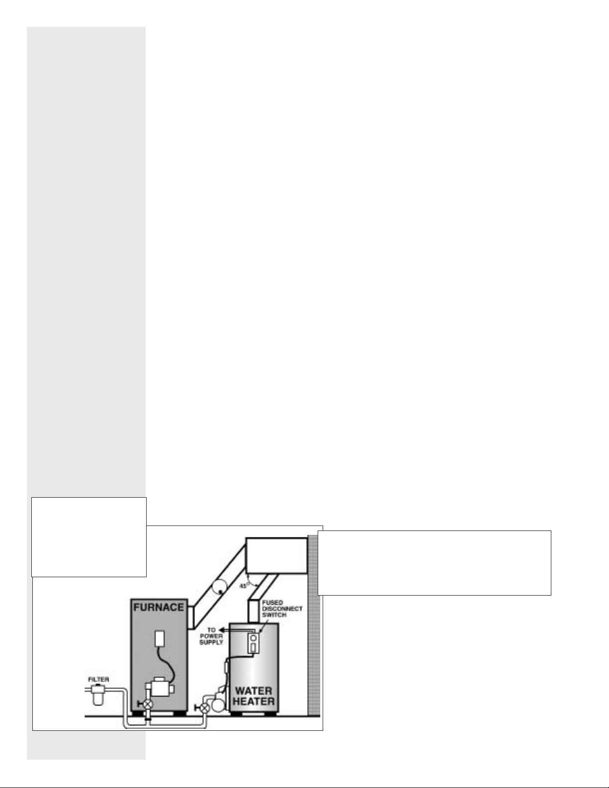
FIGURE 1
TER HEA
WHEN THE W
BINED APPLIANCE
CONTACT THE LOCAL DISTRIBUTOR OR THE FACTORY FOR INSTALLATION INSTRUCTIONS ON
“SYSTEM PLUS”.
DO NOT INSTALL THE WATER HEATER ON COMBUSTIBLE FLOORING (see Figure 2).
contact Bock Water Heaters with questions concerning proper flooring materials.
Minimum clearance to combustible construction is:
SIDES 6"; BACK 6"; FRONT 24". The installation of
this water heater must conform with local codes and
ordinances. In the absence of local codes, the installation must comply with the National Fire Protection
Association (NFP
A
TER IS USED IN A
APPLICATION, PLEASE
Refer to NFP
A 31) Code.
COM-
A
-
31 or
– 2 –
CONNECT WATER
PIPING
Connect the water piping, being careful not to apply heat to the heater
nipples. Install dielectric unions and shut off valves on both hot and cold water
l
ines.
Hot water outlet
(“HOT”) is on tank
top. Cold water inlet
is on right front
bottom of 33E and
40E. On all other
models, cold water
inlet is on tank top.
The 40E and all “C” models (example: 32EC, 51PPC) have a 1” NPT tapping located on the front left side of the tank. This is an alternate outlet for use with combined
appliance applications. If this fitting is not used, plug it with a fitting suitable for
potable water.
A 1” NPT fitting is also located behind the drain valve on the 40E and all
“C” models. This is for use as an alternate inlet or a combined appliance return.
Your heater is shipped with a reducer in this location to mount
the drain valve.
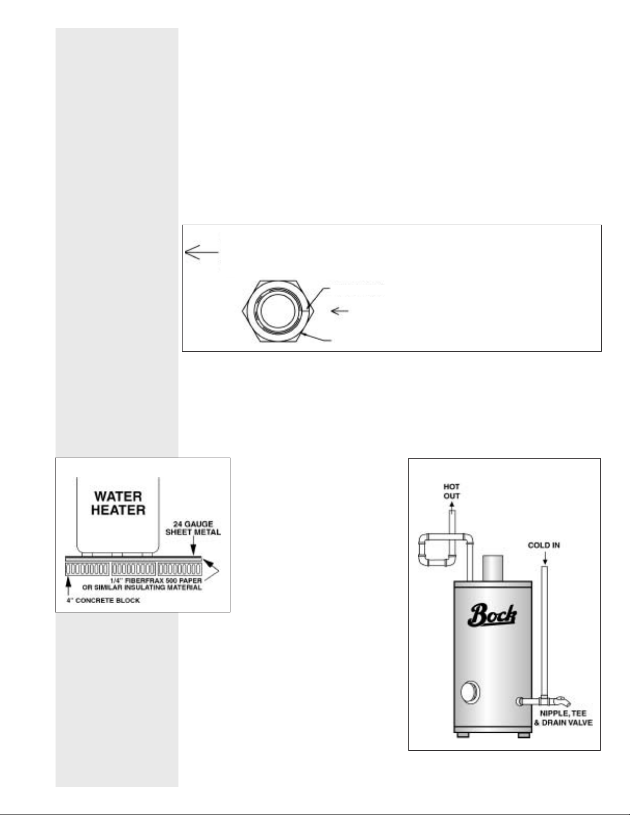
NOTE: INDEX MARK ON INLET BUSING MUST
OINT TOWARD ARROW ON DECAL. HOLD
P
USHING OR NIPPLE WHEN TIGHTENING
B
INLET
FITTINGS. ROTATING BUSHING COULD DRASTI-
ALLY REDUCE PERFORMANCE.
C
INDEX MARK
INLET BUSHING
The 33E and 40E models are equipped with a
brass inlet bushing installed in the tank. Heat-
equipped with this bushing are marked next
ers
to the inlet by the decal shown on the left. The
purpose of this bushing is to help keep the tank
bottom free of sediment by aiding tank flushing.
This bushing must be located as shown on the
decal to function properly. Do not allow the bushing to rotate out of position when tightening the
inlet fittings. In installations requiring high flow
rates, contact the factory.
The drain valve fitting may be used as an alternate cold water inlet on heaters
equipped with a dip tube, as shown in Figure 3. By plumbing a “T” into the drain
fitting, the cold water inlet can be relocated to this point. The dip tube
must be
removed and its fitting plugged. Figure 3 also shows a copper loop heat trap
installed on the hot water outlet to reduce standby losses.
FIGURE 2
The drain valve fitting may be used as
an alternate cold water inlet on heaters
equipped with a dip tube, as shown in
Figure 3. By plumbing a “T” into the drain
fitting, the cold water inlet can be
relocated to this point. The dip tube
must
be removed and its fitting plugged.
Figure 3 also shows a copper loop heat
trap installed on the hot water outlet to
reduce standby losses.
Note: When converting to this configuration on an existing heater
inspect the heater and make certain it
does not have scale buildup on the
bottom of the tank. Scale can restrict the flow
of water into the tank.
CAUTION!!
damage can occur from either the manual
lifting of the lever or the normal operation of the
valve if it is not piped to a proper drain. If
T&P
the valve fails to flow water or reseat, call
a plumber
Scalding injury and/or water
.
, visually
FIGURE 3
– 3 –

Inspect the incoming water line for check valves or water pressure reducing
v
alves. Any type of check valve may cause pressure to build up in the heater and
cause tank failure. If the heater is installed in a closed system or if backflow prev
enters and pressure regulators are installed, add an expansion tank. Do not try
to heat hard water. Install a water softener if the heater is being used in a hard
water area (water hardness more than 7 grains).
An approved temperature and pressure (T&P) relief valve is factory installed in
the opening provided in the upper right hand side of the heater. Pipe the T&P to
within 6" of the floor or to a floor drain with a free flowing drain pipe. Do not install
a check valve in the cold water line.
CONNECT TO
CHIMNEY
MOUNT THE OIL
BURNER
Using “L” or “A” type venting, connect the heater to the chimney. Use the same
size smoke pipe as the heater flue pipe (on models 20e, 20pp, 32E, 32PP and
33E, you may use 4" with a reducer if needed).
WARNING:
120E, do not reduce the smoke pipe diameter. Run a separate smoke pipe from
the water heater to the chimney wherever possible.
If it is necessary to tee into an existing smoke pipe, be sure the connector being
teed into is large enough to accommodate the products of combustion of all units
attached to it. When teeing into another connector, run in at 45° angle (see Figure
1). Install a draft regulator control only if necessary. Overfire draft should not be
positive. Stack draft should be -.02” W.C. minimum to -.05” W
should be a minimum of 11%. If a draft control is installed on the chimney,
another one on the heater is not needed.
The oil burner is equipped with a primary relay
well is packed with the burner. The thermostat is factory set at 120°F for residential use (see caution on page 1 regarding temperature variations). Install the
immersion well with the aquastat and check the bulb length (see “Burner &
Controls” section, page 10).
Remove the cardboard core from the burner opening. Mount the burner on stud
bolts and place the gasket (supplied) between the burner flange and the heater.
Secure the burner to the heater with 1/4 -20 nuts (supplied). Open the inspection
door on the heater and check the burner tube with a mirror before firing to
be sure the opening is not blocked (see Maintenance and Service sections on
pages 6 and 7 for troubleshooting).
On Models 40E, 5OES, 50ESC, 51E, 51EC, 51PP, 51PPC. 71E and
.C. maximum; CO2
. An aquastat with immersion
CONNECT THE
ELECTRICITY
CONNECT THE OIL
LINE
WARNING!! WHEN YOU
INSTALL THE BYPASS
PLUG YOU MUST RUN A
TWO-LINE SYSTEM.
– 4 –
All wiring must comply with applicable codes and ordinances. The primary relay
is wired to the burner at the factory. Install the aquastat well in the 3/4" tapping at
the front of the heater. Be sure the sensing bulb is inserted all the way into the
well. For Honeywell aquastats, tighten the screw on top of the aquastat to secure
the control to the well. For Carlin EZ-Temp aquastats, refer to the pre-packaged
installation guide for proper set-up procedure. Refer to drawings for correct models. Connect the power supply to the aquastat and run through a fused disconnect switch (attached to heater in field). See Figure 1.
Gravity System: The oil burner is normally equipped with a single-stage pump
equipped for one line (gravity) flow. Use 1/2" O.D. soft copper tubing and attach
with flared fittings. DO NOT
off valve and oil filter in the oil line. Follow the pump manufacturer’s instructions
(attached to the pump).
Lift System: The burner should be ordered with a 2-stage pump. Run a 2-line
system (suction and return lines). Install the bypass plug according to the
USE COMPRESSION FITTINGS. Install the shut
instructions attached to pump (plug is in a bag with an instruction sheet).
 Loading...