

Bock Water heaters 32 PG, 33 PG, 40 PG, 50 ESPG, 51 PG Instruction Manual
...
To the Installer:
Please attach these instructions
next to the water heater.
To the Consumer:
Please read these and all component
instructions and keep for future reference.
Power Gas
Instruction Manual
Warranty, Registration Card and Parts List are included.
Homeowner: Please remember to return
the Registration Card!
WARNING
Improper installation, adjustment, alteration,
service or maintenance can cause serious injury or property damage. Refer to this manual.
For assistance or additional information, consult a qualified installer or service agency.
WARNING
If the information in these instructions is not
followed exactly, a fire or explosion may result
causing property damage, personal injury or
death.
WARNING
Do not install on combustible flooring. Install
in accordance with all local codes. In the
absence of local codes, refer to NFPA 54 or
ANSI Z21.10.1.
CAUTION
The recommended temperature for normal residential use is 120°F. The dial on the aquastat
does not always reflect the out-coming water
temperature and it could occasionally exceed
120°F. Variation in out-coming temperature
could be based on factors including but not
limited to usage patterns and type of installation. Test water at the tap nearest to the water
heater. (See page 8 for measuring the outcoming water temperature.)
WARNING
Hotter water increases the risk of scald injury.
Before adjusting the water temperature setting,
read this instruction manual. Temperatures at
which injury occurs vary with the person’s age
and the length of exposure. The slower reaction time of children, elderly or physically or
mentally challenged persons increases the
scalding hazard to them. It is recommended
that lower water temperatures be used where
these exposure hazards exist. Households with
small children or invalids may require a temperature setting less than 120°F to prevent accidental contact with hot water. To produce
less than 120°F, use point-of-use temperature limiting devices.
If higher water temperature is needed in part
of the water system, automatic temperature
limiting devices must be used on all lines to
water taps.
WARNING
Flammable vapors may be drawn to this water
heater from other areas of the structure by air
currents. Do not store or use any flammable
liquids in the vicinity of this heater.
WARNING
Water heater blankets may restrict air flow to
the water heater and cause fire, asphyxiation,
personal injury or death.
THIS MANUAL HAS BEEN PREPARED TO
ACQUAINT YOU WITH THE INSTALLATION,
OPERATION, AND MAINTENANCE OF YOUR
WATER HEATER AND TO PROVIDE IMPORTANT
SAFETY INFORMATION.
Read all instructions thoroughly before attempting installation or operation of your
water heater. Keep these instructions for future
reference.
Local plumbing and electrical codes must be
followed in the installation of this water
heater. In the absence of a local code use the
UNIFORM PLUMBING CODE and the NFPA
Code. Local codes may supersede instructions
in this installation manual.
These instructions are a guide for the correct
installation of the water heater. The manufacturer will not be liable for damages caused by
failure to comply with the installation and
operating instructions outlined on the
following pages.
If you lack the necessary skills required or have
difficulty following the directions, seek help
from a qualified person for that part of the
installation you do not understand.
FAILURE TO FOLLOW THESE INSTRUCTIONS
OR ALL APPLICABLE BUILDING CODES
AND REGULATIONS VOIDS THE WARRANTY
ON THIS WATER HEATER.
H
OT OUTLET
C
D
B
AUXILIARY OUTLET
(
COMBINED APPLIANCE)
C
OLD INLET
AQUASTAT
R
ETURN
A
E
HOT OUTLET*
A
QUASTAT
B
C
H
IGH LIMIT 50, 73, 120, 190, 241, 361, 541
C
OLD INLET (EXCLUDES MODEL 541)
RETURN FOR MODELS
120, 190, 241 & 361
M
ODEL 541 (INLET/RETURN)
RETURN
3
2, 51,
71, 72,
7
3
E
A
D
*nipples not supplied on all models
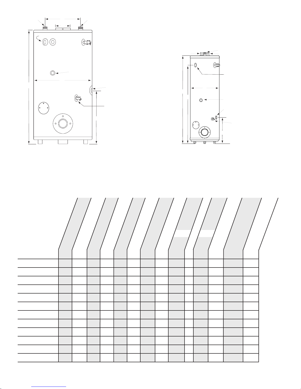
32, 50, 51, 71, 72, 73, 120, 190, 241, 361, 541 PG
POWER GAS
Instruction Manual
(Thousands)
(F)
(GPH)
Dimensions
33, 40 PG
(V/Hz)
(inc. burner
(lbs.)
and controls)
(gal.)
BTUH
Storage Capacity
32 PG 32 1041⁄23⁄4''3⁄4''3⁄4'' 90° 110 51'' 20'' 6'' 11'' 17'' 120/60 260
33 PG 33 1041⁄23⁄4''3⁄4''3⁄4'' 90° 109 431⁄4" 24'' 6'' N/A 171⁄4'' 120/60 270
40 PG 40 1261⁄23⁄4''3⁄4'' 1'' 90° 134 61'' 20'' 6'' 54'' 18'' 120/60 295
Minimum
Cold Inlet
Gas Connection
50 ESPG 50 1401⁄2 1" 11⁄2"11⁄2" 90° 142 52" 26" 6" 131⁄2" 181⁄2" 120/60 345
51 PG 50 1521⁄2 1'' 1''3⁄4'' 90° 159 59'' 24'' 6'' 11'' 18'' 120/60 330
71 PG 68 1731⁄2 1" 11⁄2"11⁄2" 90° 170 66" 26" 6" 131⁄2" 22" 120/60 395
72 PG 67 1991⁄2 1" 11⁄2"11⁄2" 90° 204 58" 28" 8" 16" 19" 120/60 560
73 PG 67 2423⁄4 1" 11⁄2"11⁄2" 90° 247 58" 28" 8" 16" 19" 120/60 560
120 PG 113 1551⁄2 1'' 2'' 2'' 90° 160 67'' 311⁄2'' 6'' 19'' 22'' 120/60 700
190 PG 113 1901⁄2 1'' 2'' 2'' 90° 191 67'' 311⁄2'' 6'' 19'' 22'' 120/60 700
241 PG 109 2773⁄4 1" 2" 2" 90° 283 67" 311⁄2" 8" 19" 22" 120/60 935
361 PG 91 3853⁄4 1" 2" 2" 90° 435 67" 311⁄2" 9" 23" 26" 120/60 1110
541 PG 83 623 1" 2" 2" 2" 90° 627 66" 34" 10" N/A 301⁄2" 120/60 1350
Page 2 Power Gas
Return
Hot Outlet
Recovery
Temperature Rise
C
A
B
D
E
Voltage
Weight
(Non ASME)
WHEN YOU RECEIVE YOUR NEW WATER HEATER
Check the new equipment to see if all components are in good condition. The water heater and
burner may be shipped as separate units. The aquastat and immersion well are packed with the
burner. If damage is observed or parts appear to be missing, contact your wholesaler. A burner
installation and setup manual is also packed with the burner.
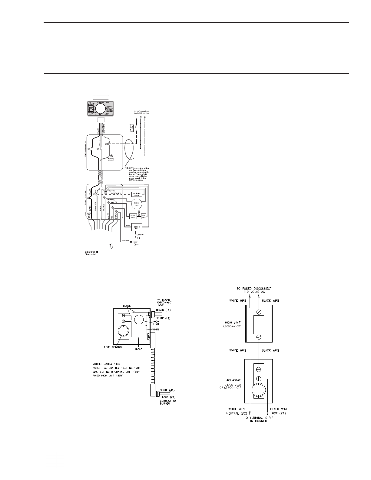
BURNER WIRE DIAGRAM
Carlin burner w/ Carlin EZ-Temp
Models 32, 33, 40, 50, 51, 71, 72, 73, 120, 190PG
Honeywell 4103A-1142 Honeywell L4006-2031, L8100C-1027
Models 32,33,40,51,71,72PG Models 50,73,120,190,241,361,541PG
Midco burner w/ Carlin EZ-Temp ( all models)
Power Flame burner w/ Carlin EZ-Temp ( only 541 PG)
Power Gas Page 3
WATER HEATER PLACEMENT
NOTE: Locate the heater so it is not subject to physical damage from moving vehicles or
flooding. Do not locate the water heater in a room where swimming pool chemicals or large
Please consult local codes, NFPA 54 and/or contact Bock Water Heaters with questions concerning
proper flooring materials. Leave adequate room for periodic maintenance of heater and burner.
The water heater should be placed as near to the chimney as practical in order to keep vent connector length to a minimum. Consult National Fuel Gas Code for proper vent configuration.
Minimum clearance to combustible construction is: SIDES 6"; BACK 6"; FRONT 24";
BAROMETRIC DRAFT REGULATOR, 18". The installation of this water heater must
conform with local codes and ordinances. In the absence of local codes, the installation must comply with the National Fire Protection Association (NFPA 54) Code.
quantities of water softener salt are kept. Installing a water heater
in this environment will result in premature failure of tank and
burner components due to corrosion caused by these elements
diffusing into the air.
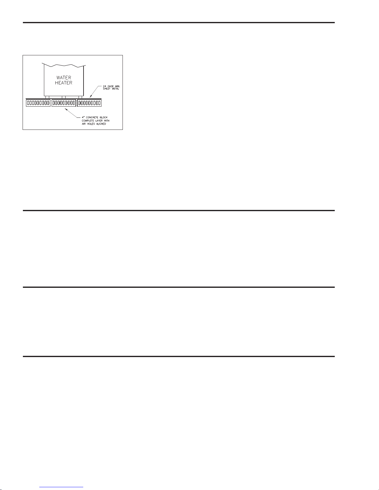
DO NOT INSTALL THE WATER HEATER ON COMBUSTIBLE
FLOORING. Place on noncombustible flooring and maintain clear-
ances prescribed by this manufacturer and per code NFPA 54. If the
water heater must be located on combustible flooring it must be
raised off the floor with a layer of 4'' concrete block laid so the air
holes are aligned as shown in the drawing at left. Consult with local
code officials before using this method. Do not use on 541 PG.
COMBUSTION AND VENTILATION AIR
The water heater must be installed in a location with an adequate air supply for combustion,
ventilation and draft control. Lack of an adequate air supply will result in poor burner/water
heater performance and nuisance lock outs. Unsafe levels of carbon monoxide (CO), condensation and sooting may result if the room does not have an adequate air supply. See “National
Fuel Gas Code (NFPA 54)” or the discussions of “Unconfined Space” and “Confined Space”
below. Poor ventilation will also result in hot spots around the heater. Temperatures over 90°
near the water heater generally indicate a lack of ventilation.
UNCONFINED SPACE
Unconfined space in defined by NFPA 54 as a space with a volume greater than 50 cubic feet
(during typical use) per 1000 BTUH of the total combined input of all fuel burning appliances
in the space. Rooms leading directly to the installation space through doors that cannot be
closed can be considered part of the space. Exception: Buildings with full vapor barriers, tight
doors and windows or air infiltration rates of less than 0.35 air changes per hour will be considered a confined space and require additional air supplies.
CONFINED SPACE
Confined space is defined by NFPA 54 as a space with a volume less than 50 cubic feet (during
typical use) per 1000 BTUH of the total combined input of all fuel burning appliances in the
space. Buildings or rooms of unusually tight construction are also considered a confined space.
See “Unconfined Space: Exception”.
When installing fuel burning appliances in a confined space, air must be supplied to that
space from either inside or outside of the building as conditions allow.
A. Inside Air Supply: A confined space shall be provided with two permanent openings; one
within 12 inches of the top and one within 12 inches of the bottom of the enclosure. These
openings shall lead directly to room(s) of sufficient volume so that the combined volume of
all the space meets the criteria for unconfined space. Each opening shall have a minimum
free area of 1 square inch per 1000 Btu/hr of the combined total input of all fuel burning
Page 4 Power Gas
 Loading...