

Bock Water heaters 32E, 32PPC, 50ES, 51EC, 33E Installation, Operation & Maintenance Instructions Manual
...
TO THE INSTALLER:
Please attach these in -
struc tions next to the
water heater.
TO THE CONSUMER:
Read these and all com -
po nent in struc tions.
Please keep for fu ture
reference. Pleas e re mem ber to return the
registration card.
Waranty, regist ration
card & parts list in clud ed.
INSTALLATION, OPERATION &
MAINTENANCE IN STRUC TIONS
BOCK RESIDENTIAL OIL-FIRED
WATER HEATERS
Model numbers: 32E, 32PPC, 33E, 50ES,
51EC, 51PPC, 120E
WARNING:
Improper installation, adjustment, alteration, ser vice
or maintenance can cause serious in ju ry or prop erty damage. Refer to this man u al. For as sis tance
or additional in for ma tion, con sult a qual i fied in stall er
or service agency.
WARNING:
If the information in these instructions is not fol lowed exactly, fire or explosion may result and can
cause property damage, personal in ju ry or death.
WARNING:
Follow minimum combustible clearance as noted
on wa ter heater label. Do not in stall on com bus ti ble flooring (see Figure 2, Page 3). In stall in ac cor dance with all lo cal codes. In the ab sence of local
codes, re fer to NFPA 31.
CAUTION:
The recommended temperature for normal residen tial use is 120°F. The dial on the aquastat does not
always reflect the outcoming water tem per a ture,
which could occasionally exceed 120°F. The vari a tion in outcoming tem per a ture could be based on
factors including but not limited to us age pat terns
and type of installation. Test your water at the tap
nearest to the water heater. (See page 5 for mea sur ing the outcoming water tem per a ture).
WARNING:
Hotter water increases the risk of scald injury. Be fore changing the temperature setting, read the
in struc tion manual. Tem per a tures at which injury oc curs vary with the in di vid u al’s age and length of
ex po sure.
The slower reaction times of children, elderly and
physically or mentally impaired persons in creas es
the scald ing hazard to them. It is rec om mend ed low er
wa ter temperatures be used where these sit u a tions
exist.
Households with small children or invalids may re quire a tem per a ture setting less than 120°F to pre vent
accidental contact with hot water.
To lower water temperature use point-of-use tem per a ture limiting devices.
WARNING:
Flammable vapors may be drawn to this wa ter heat er from other areas of the struc ture by air currents.
Do not store or use any flam ma ble liquids in the
vicinity of this heater.
WARNING:
Water heater blankets may not be used on the
heater and may cause fire, asphyxiation, per son al
injury or death.
23420 Rev 10 (9/17)
110 South Dickinson Street • Madison, WI 53703
Phone: 608/257-2225 • Fax: 608/257-5304 • www.bockwaterheaters.com
Bock Water Heaters, Inc.

CONSUMER
RE SPON SI BIL I TIES
THIS MANUAL HAS BEEN PREPARED TO ACQUAINT YOU WITH THE IN STAL LA TION, OP ER A TION, AND MAINTENANCE OF YOUR WATER HEATER AND
TO PRO VIDE IM POR TANT SAFETY INFORMATION.
FAILURE TO FOLLOW
THESE INSTRUCTIONS
OR ALL APPLICABLE
BUILD ING CODES AND
REG U LA TIONS VOIDS
THE WAR RAN TY ON THIS
WATER HEAT ER.
MULTIPLE BURNER
INSTALLATION
Read all instructions thoroughly before attempting installation or operation of the
water heat er. Keep these and all component instructions for future ref er ence.
The manufacturer of this water heater will not be liable for any damages caused
by failure to comply with the installation and operating instructions outlined on the
fol low ing pages. These instructions are a guide for the correct installation of the
water heater.
If the installer lacks the necessary skills or has difficulty following the
di rec tions, do not pro ceed but get help from a qualified person for that part of the
installation that is not un der stood.
Local plumbing and electrical codes must be followed in the installation of this
water heater. In the absence of a local code use the UNIFORM PLUMBING CODE
and the NFPA Code. Local codes may supersede instructions in this installation
manual.
When two or more burners are used, each unit should have a separate
supply line to the fuel pump to prevent nuisance lockouts caused by one or both
pumps starving for oil. If this is not possible, the use of a priority
control is recommended.
Check new equip ment to see if all com po nents are in good con di tion.
The wa ter heater and oil burner may be shipped as sep a rate units. The aquastat
and im mer sion well may be packed with the oil burner.
SELECT THE RIGHT
LOCATION
Check for exhaust fans in
the heater room or ad ja cent ar eas which draw
com bus tion air away from
heater. THE HEATER
MUST HAVE COM BUS TION AIR TO OP ER ATE.
The new water heater re quires fuel (#I or #2 heat ing oil), electricity and should be
close to the chim ney and water supply. Lo cate the heater near a floor drain if pos si ble for easy main te nance and protection if trouble should occur. Allow ample
space around the heater for servicing (see combustible clearance warning, page
1). Ad e quate air for com bus tion must be available. NOTE: Locate the heater so it
is not subject to physical damage by moving vehicles or possible flood ing.
DO NOT INSTALL THE WATER HEATER ON COM BUS -
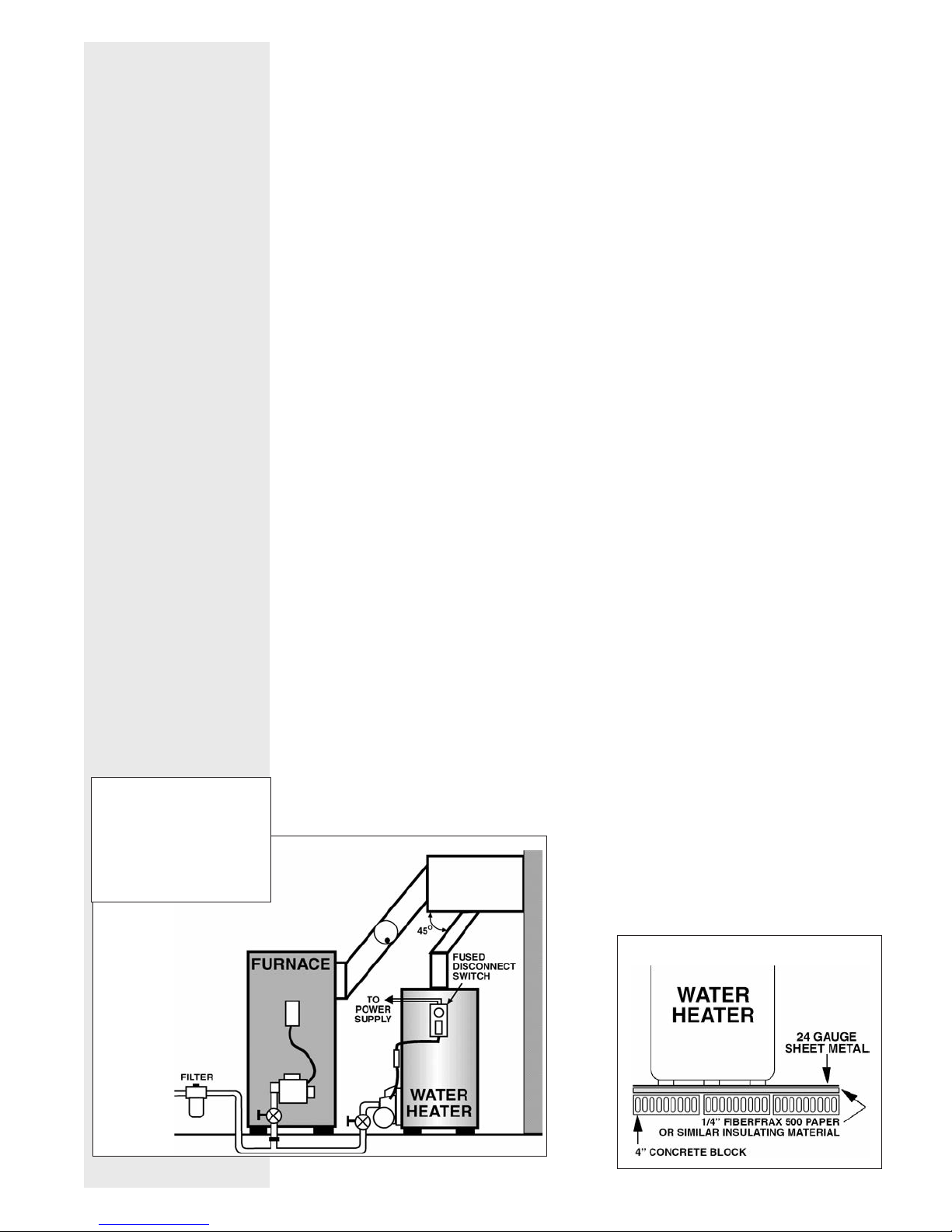
FIGURE 1
TI BLE FLOORING (see Figure 2).
con tact Bock Wa ter Heat ers with questions con cern ing
prop er floor ing ma te ri als.
Minimum clearance to combustible con struc tion is:
SIDES 6"; BACK 6"; FRONT 24". The in stal la tion of
this water heater must con form with local codes and
or di nanc es. In the absence of local codes, the in stal la tion must comply with the Na tion al Fire Pro tec tion
As so ci a tion (NFPA 31) Code.
Refer to NFPA 31 or
FIGURE 2
– 2 –

CONNECT WA TER
NOTE: INDEX LINE ON INLET NIPPLE
MUST BE ALIGNED WITH ARROW ON
DECAL. HOLD INLET NIPPLE WH EN
TIGHTENING FITTINGS. ROTATI NG
NIPPLE COULD DRASTICALLY REDUCE
PERFORMANCE.
PIPING
Connect the water piping, being careful not to apply heat to the heater
nipples. Install di elec tric unions and shut off valves on both hot and cold water
lines.
Model 33E is equipped with an inlet flow diverter installed
in the tank. This model contains decal next to the inlet
(shown to the left). The purpose of this diverter is to help
keep the tank bottom free of sediment by aiding tank
flushing. The index line on the diverter nipple must be
aligned with the arrow on the decal (left) to function
properly. Do not allow the diverter to rotate out of position
when tightening the inlet fittings.
CAUTION!! Scalding injury and/or water dam age can
occur from ei ther the manual lifting of the lever or the
normal op er a tion of the T&P valve if it is not piped to a
proper drain. If the valve fails to flow water or reseat, call a
plumb er.
CONNECT TO
CHIMNEY
MOUNT THE OIL
BURN ER
Inspect the incoming water line for check valves or water pres sure re duc ing
valves. Any type of check valve may cause pres sure to build up in the heater and
cause tank failure. If the heat er is in stalled in a closed system or if backflow
preventers and pressure reg u la tors are in stalled, add an ex pan sion tank. Do not
try to heat hard water. Install a water soft en er if the heat er is being used in a hard
wa ter area (water hardness more than 7 grains).
An ap proved temperature and pressure (T&P) relief valve is factory installed in the
opening provided in the upper right hand side of the heater. Pipe the T&P to within
6" of the floor or to a floor drain with a free flowing drain pipe.
Install a vent connector between the chimney and the water heater. The size of
the vent connector shall be acceptable based on the rise in height of the connector and the water heater input.
If it is necessary to connect to an existing vent connector, be sure the connector
utilized is large enough to ac com mo date the products of com bus tion of all units
at tached to it. When utilizing an oth er connector, run in at 45° angle (see Figure 1).
Install a draft regulator con trol only if nec es sary. Overfire draft should not be pos i tive. Breech draft should be -.03” W.C. min i mum to -.05” W.C. maximum; CO2
should be a minimum of 11% with zero smoke on the Bacharach scale.
The oil burner is equipped with a primary relay. An aquastat with immersion
well is packed with the burner. The thermostat is factory set at 120°F for residential use (see caution on page 1 regarding temperature vari a tions). Install the
immersion well with the aquastat and check the bulb length (see “Burner &
Controls” section, page 10).
Remove the cardboard core from the burner opening. Mount the burner on stud
bolts and place the gasket (sup plied) between the burner flange and the heater.
Secure the burner to the heater with 1/4 -20 nuts (supplied). Open the inspection
door on the heater and check the burner tube with a mirror before firing to
– 3 –
be sure the open ing is not blocked (see Maintenance and Service sections on
pages 6 and 7 for troubleshooting).

CONNECT THE
ELECTRICITY
All wiring must comply with applicable codes and ordinances. The primary relay is
wired to the burner at the factory. Install the aquastat well in the 3/4" tapping at
the front of the heater. Be sure the sensing bulb is inserted all the way into the
well. For Honeywell aquastats, tighten the screw on top of the aquastat to secure
the control to the well. For Carlin EZ-Temp aquastats, refer to the pre-packaged
installation guide for proper set-up procedure. Refer to drawings for correct
models. Connect the power supply to the aquastat and run through a fused dis con nect switch (attached to heater in field). See Figure 1.
CONNECT THE OIL
LINE
WARNING!! WHEN YOU
INSTALL THE BYPASS
PLUG YOU MUST RUN A
TWO-LINE SYSTEM.
A properly sized and rated oil filter shall be installed in the oil supply line
(NFPA 31, 4.5.4).
Gravity System: The oil burner is normally equipped with a single-stage pump
equipped for one line (gravity) flow. Use minimum 3/8" O.D. soft copper tubing and
attach with flared fit tings. DO NOT USE COM PRES SION FITTINGS. Install the
shut off valve and oil filter in the oil line. Follow the pump man u fac tur er’s instructions (attached to the pump).
Lift System: The burner should be ordered with a 2-stage pump. Run a 2-line
system (suc tion and
return lines). Install the bypass plug according to the
instructions attached to pump (plug is in a bag with an instruction sheet).
For any horizontal run exceeding the maximum length specified in Figure 3, or any
lift of more than 10 feet, a booster pump must be used. Boost er pumps must be
installed as close to the oil supply tank as possible. Suction and return lines
should be the same diameter and both go within 6” of the bottom of the tank. The
return line should stop slightly above the suction line. Use a minimum of fittings.
Make bends in the tubing with as large a radius as possible. DO NOT USE
COM PRES SION FITTINGS. Caution must be used in the final connection to the
burner so as not to strain the fuel unit. Before attaching the tubing to the burner,
form a coil in the tubing to minimize any vibration. State and local codes must be
followed.
PLACE THE WATER
SYSTEM IN
OPERATION
FIGURE 3: MAXIMUM LIFT & HORIZONTAL RUN
1-Pipe Single Stage Horizontal 2-Pipe Two-Stage Horizontal
System Pump Run System Pump Run
3/8” O.D. 1/2” O.D. 3/8” O.D. 1/2” O.D.
Lift Tube Tube Lift Tube Tube
0’ 65’ 100’ 0’ 75’ 100’
4’ 45’ 100’ 4’ 64’ 100’
7’ 31’ 100’ 7’ 55’ 100’
8’ 16’ 64’ 10’ 47’ 100’
Your log (or one similar to this) must be filled out as follows:
Date Time Test person’s name Set temp. oF Outlet temp. oF
1. Fill the tank with water, opening a hot water faucet to allow trapped air to
escape from the heater. Open the cold water inlet valve. Shut off each faucet as it
delivers water that is free of air. Inspect for leaks. Never operate an empty or
partially full heater.
– 4 –

2. To place burner in operation, follow the instructions provided with the burner.
3. Set the pump pressure to 100 PSI for Wayne, Carlin and Beckett burners and
150 PSI for Riello burners.
Warning: Handhole
cover may loosen
during ship ping –
check for tightness
before putting heater
in operation.
MEASURING
THE
OUTCOMING
WATER
TEMPERATURE
4. Adjust the burner combustion air in accordance with the burner manufacturer’s
instructions. Us ing com bus tion in stru ments, check the C02 and smoke. The C02
should be at least 11% min i mum with zero smoke on the Bacharach scale.
5. While the burner is operating, disconnect one of the yellow cad cell wires.
Check to see that the burner control locks out in the time specified on the control.
Reattach the wire and reset the control. The burner should restart. Note: You may
have to wait a minute before resetting the control.
6. The thermostat is factory set at 120°F for residential use. (See caution on
page 1 re gard ing tem per a ture variations. It is the responsibility of the homeowner
and installer to verify that the installer follows the rec om mend ed quantitative
testing for measuring the outcoming water tem per a ture. To make sure that the
system works properly after installation and in the future, it is rec ommend ed that
the heater’s per for mance be measured and monitored. Run water out of the tap
nearest the heater until it comes out warm. Using a calibrated thermometer, take
a mea sure ment. If the water is not at a suitable tem per a ture for the installation,
have a qual i fied service person adjust the aquastat. Contact Bock for further
information on the ther mom e ter if need ed.
WARNING: Hydrogen gas can be produced in a hot water system served by
a heater that has not been used for a long period of time (generally two
weeks or more.) Hy dro gen gas is ex treme ly flammable. To reduce the risk of
injury, open the hot water faucet at the highest lo ca tion in the house for
several minutes before using any electrical ap pli ance connected to the hot
water system. If hy dro gen is present, there may be an un usu al sound such
as air escaping through the pipe as the water begins to flow. Do not smoke
or allow an open flame near the faucet at the time it is open.
MAINTENANCE
SERVICE
1. Follow the burner manufacturer’s instructions for proper maintenance of the oil
burner.
2. EVERY SIX to 12 MONTHS. Drain water from the heater tank and inspect for
sed i ment or lime ac cu mu la tion. Flush out if necessary. If lime has accumulated,
remove with a com mer cial compound for dissolving lime or by scraping through
the hand hole opening (if supplied). Check water softening equip ment if lime is
found in the tank. DO NOT ATTEMPT TO HEAT HARD WA TER. (See
maintenance label on heater.)
3. Change the magnesium anode rods every six to 12 months or when they
are re duced to 3/8” diameter (see maintenance label on heat er).
4. Open the relief valve test lever to flush out the tank. Make sure it reseats itself.
5. If the heater is to be shut off in cold weather, drain the tank to prevent freezing.
1. Check the fuel supply, electrical wiring and fuses, and make sure temperature
control is calling for heat.
2. If the burner fails to operate, call a qualified local service provider.
– 5 –
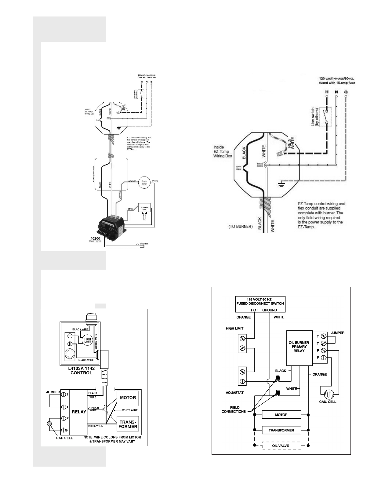
WIRING
FIGURE 4: Carlin burner w/ Carlin EZ-Temp
For Models: 32, 33, 50, 51, 120
(see burner manufacturer’s instructions for 20e;
60200 primary w/ three wire harness)
FIGURE 5: Beckett or Wayne burner w/ Carlin EZ-Temp
For Models: 32, 33, 50, 51, 120
FIGURE 6: Honeywell L4103A-1142
For Models: 32, 33, 51
FIGURE 6 NOTES:
Set point 120°
FIGURE 7: Honeywell L4006A w/ L8080B
For Models: 50, 120E
High limit: 190°
Aquastat:
120° set point
15° differential
L4080B
L4006A
– 6 –
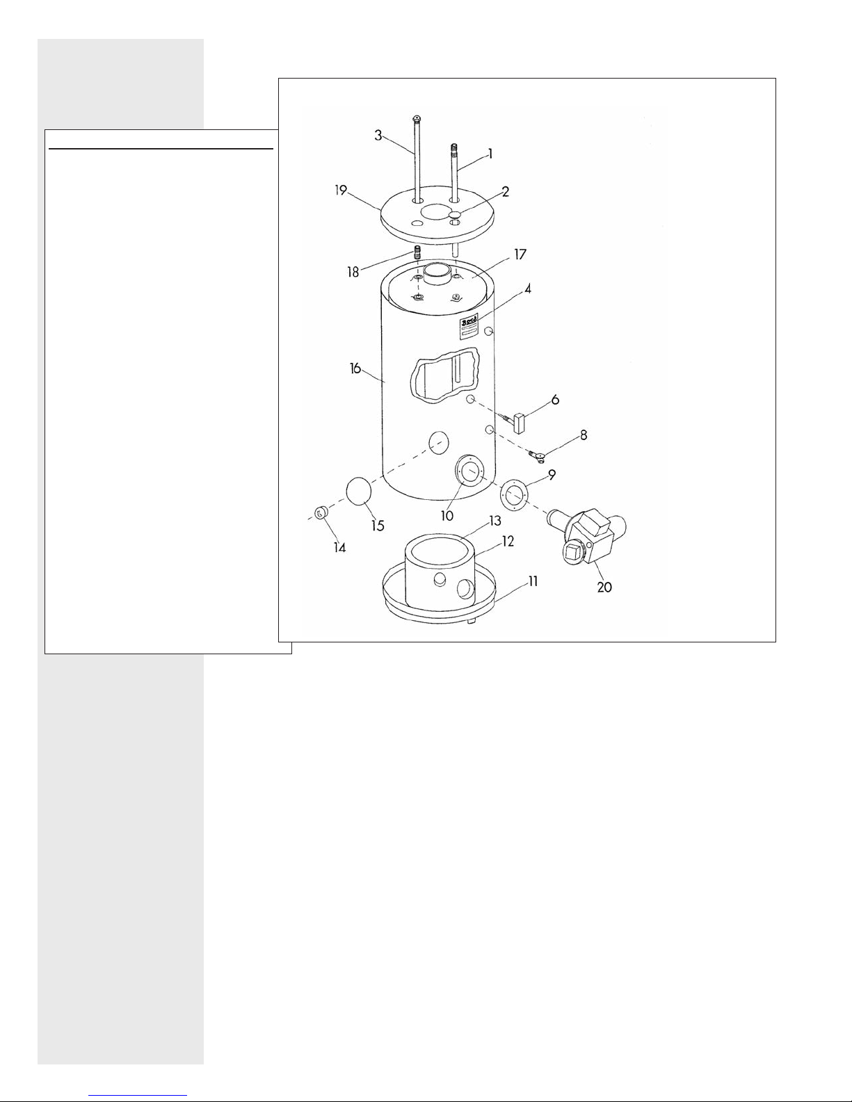
ITEM DESCRIPTION
1. Cold Water Inlet Dip Tube
(N/A 33E)
2. Plastic Cap
3. Magnesium Anode Rod
(aluminum avaliable)
4. Name Plate/Rating Label
6. Immersion Well & Aquastat
8. Drain Valve
9. Mounting Bracket Gasket
10. Burner Mount ing Bracket
(part of jacket assembly on Models
32E through 51 Series; sold
sep a rate ly on 120E)
11. Bottom Pan
12. Combustion Chamber Sleeve
13. Com bus tion Chamber
14. Inspection Block
15. Inspection Door
16. Heater Jacket
17. Tank
18. Hot Out Nipple
51 Series: 1”
AlI others: 3/4”
50ES: N/A
19. Top Pan
20. Burner
OIL FIRED WATER HEATER
BOCK TANK ASSEMBLY
PARTS LIST
When ordering repair parts, always give
the part name, model num ber, size and
serial number.
Handhole cover plate and gasket
(for 50ES only) not shown.
– 7 –
 Loading...