

Bock Water heaters 30ST, 50ST, 80ST, 119ST Instruction Manual
To the Installer:
Please attach these instructions
next to the water heater.
To the Consumer:
Please read these and all component
instructions and keep for future reference.
Storage Tanks
Instruction Manual
Warranty, Registration Card and Parts List are included.
Owner: Please remember to return
the Registration Card!
WARNING
Improper installation, adjustment, alteration,
service or maintenance can cause serious
injury or property damage. Refer to this
manual. For assistance or additional
information, consult a qualified installer or
service agency.
CAUTION
The recommended temperature for normal
residential use is 120°F. The dial on the aquastat
does not always reflect the out-coming water
temperature and it could occasionally exceed
120°F. Variation in outcoming temperature
could be based on factors including, but not
limited to, usage patterns and type of
installation. Test water at the tap nearest to
the water heater and storage tank.
WARNING
Hotter water increases the risk of scald injury.
Before adjusting the water temperature setting,
read this instruction manual. Temperatures at
which injury occurs vary with the person’s age
and the length of exposure. The slower
reaction time of children, elderly, or
physically or mentally challenged persons
increases the scalding hazard to them. It is
recommended that lower water temperatures
be used where these exposure hazards exist.
Households with small children or invalids
may require a temperature setting less than
120°F to prevent accidental contact with hot
water. To produce less than 120°F, use point-ofuse temperature limiting devices.
If higher water temperature is needed in part
of the water system, automatic temperature
limiting devices must be used on all lines to
water taps.
INSTALLER RESPONSIBILITIES
Please read all instructions before installing or
placing this storage tank into service. This
unit must be installed by licensed or
authorized installers, or technical personnel
that service water heating equipment. The
Storage Tank must be installed in accordance
with all local codes and ordinances.
HANDLING
Before uncrating, check for shipping damage.
Report any damage to your carrier. Note
damage on bill of lading or delivery receipt
and file a claim.
LOCATION
This storage tank should be located in a
central location to the piping system, as close
as possible to the heat source and in an area
not subject to freezing temperatures. Leave
sufficient space for servicing and maintaining
the tank.
THIS MANUAL HAS BEEN PREPARED TO
ACQUAINT YOU WITH THE INSTALLATION,
OPERATION, AND MAINTENANCE OF YOUR
WATER HEATER AND TO PROVIDE IMPORTANT
SAFETY INFORMATION.
Read all instructions thoroughly before attempting installation or operation of your
water heater. Keep these instructions for future
reference.
Local plumbing and electrical codes must be
followed in the installation of this storage
tank. In the absence of a local code use the
UNIFORM PLUMBING CODE and the NFPA
Code. Local codes may supersede instructions
in this installation manual.
These instructions are a guide for the correct
installation of the storage tank. The manufacturer will not be liable for damages caused by
failure to comply with the installation and
operating instructions outlined on the
following pages.
If you lack the necessary skills required or have
difficulty following the directions, seek help
from a qualified person for that part of the
installation you do not understand.
FAILURE TO FOLLOW THESE INSTRUCTIONS
OR ALL APPLICABLE BUILDING CODES AND
REGULATIONS VOIDS THE WARRANTY ON
THIS WATER HEATER.
23950
Rev 5 6/16
B
Drain Valve
Supply/Return Conn.
Aquastat Conn.
Supply/Return Conn.
T&P Relief Valve Conn.
C
A
D
E
Drain
Valve
30°
Relief
Valve
45°
Aquastat
0°
ANODE
ANODE
45°
Supply
Return
Hot Outlet
C
A
Supply/Return Conn.
Drain Valve
Supply/Return Conn.
Aquastat Conn.
D
E
B
T&P Relief Valve Conn.
30°
Drain
Valve
45°
Relief
Valve
0°
Aquastat
45°
Supply
Return
Hot Outlet
ANODE
ANODE
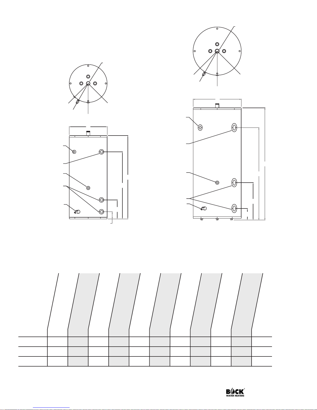
Table 1: ST Dimensions
Storage Capacity
Figure 1: 30ST, 50ST
(gal.)
T&P Fitting
Supply/
30ST 30 3⁄4'' 2'' 2'' 3⁄4'' 391⁄2'' 20'' 30'' 111⁄16'' 43⁄16'' 150
50ST 50 3⁄4'' 2'' 2'' 3⁄4'' 481⁄2'' 22'' 39'' 111⁄16'' 43⁄16'' 190
80ST 80 1'' 2'' 2'' 3⁄4'' 601⁄2'' 24'' 50'' 21'' 6'' 250
119ST 119 1'' 2'' 2'' 3⁄4'' 651⁄2'' 28'' 54'' 22'' 7'' 385
Page 2 Storage Tanks
Return Fitting
Hot Outlet
Aquastat Fitting
Figure 2: 80ST, 119ST
Dim ensi ons
A
B
C
D
(lbs.)
E
Weight
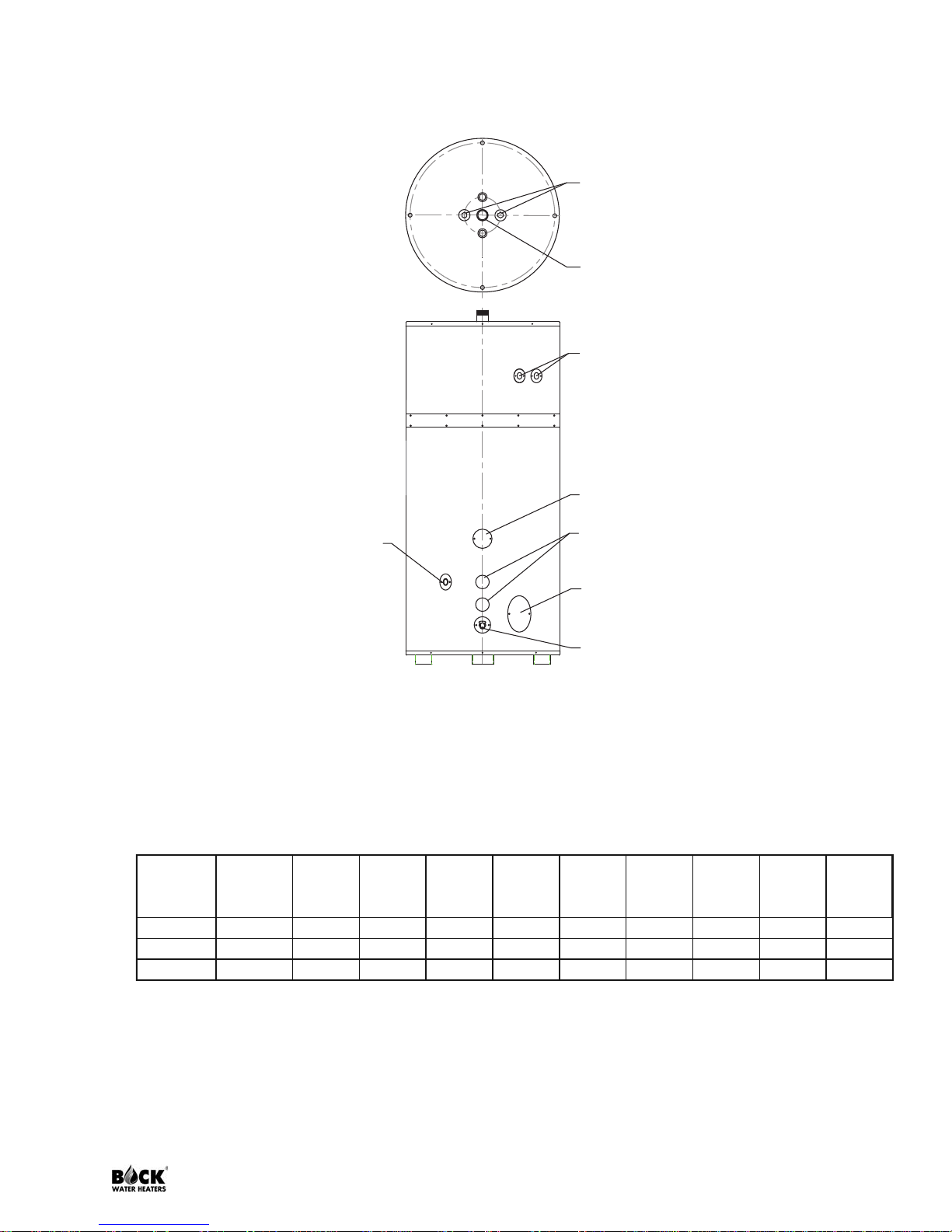
Aquastat
Connection
Drain Valve
Cleanout Hand-ho
Inlet/Return
Connections
ASME Rating Plate
(2) NPT Connection
(T&P valves NOT su
Hot Outlet
Anode Rods
Model
2”
Insulation
w/External
Jacket
Storage
(gal)
Working
Pressure
Overall
Diameter
T&P Relief
Valve
Conn.
Inlet/
Return
Conn.
Hot
Outlet
Conn.
Aquastat
Conn.
Overall
Height/
Length
Shipping
Weight
(lbs)
119ST-A-150 Standard 119 150 28”
1 x 1” NPT
2” 2” ¾” 65½” 385
200ST-A-125 Standard 200 125 34”
2 x 1” NPT
2½” 2½” ¾” 79½” 872
200ST-A-150 Standard 200 150 34”
2 x 1” NPT
2½” 2½” ¾” 79½” 872
Figure 3: ASME Vertical
Table 2: ASME ST Dimensions
Storage Tanks Page 3

WHEN YOU RECEIVE YOUR NEW STORAGE TANK
Check the new equipment to see if all components are in good condition. The T&P valves,
aquastat and immersion well are supplied by the installer.
TEMPERATURE CONTROLS
Bock storage tanks are equipped with 3⁄4'' tappings for the installation of immersion
temperature controls. Any temperature control approved for use in hot water systems is
acceptable. Bock recommends the use of a control with an adjustable differential so that the
differential can be adjusted to match that of your heat source controls. Setting the storage
tank temperature control 5° lower than the water heater temperature control is also
recommended. This is to ensure that when the storage tank calls for heat and the circulator is
turned on, the water being circulated is cool enough to cause the water heater to start. If the
burner does not start then the circulator could run for long periods of time, wasting energy.
Note: The recommended water temperature for domestic use is 120°. Higher water
temperatures can result in scalding. If higher or lower water temperatures are needed, point
of use tempering devices are recommended.
T&P VALVES
Temperature and pressure relief valves must be installed on all storage tanks by the installer.
All Bock storage tanks are also equipped with 3⁄4'' or 1'' tappings for the installation of
properly sized temperature and pressure relief valves. These are located on the side near the
top of vertical tanks and on the top surface of horizontal storage tanks. Relief valves are rated
for maximum system pressure and temperature as well as Btu input of the heating appliance.
This information is normally supplied on a metal tag attached to the end of the valve. For a
normal domestic water system maximum system pressure is 150 psi and temperature limit is
210°F. The Btu per hour rating will be listed next to the AGA or CSA logo on the tag under
the temperature and pressure data. Be certain to use a relief valve that is rated for the Btu per
hour input of the heating appliance. For example, if you are connecting a storage tank to a
water heater with a 50,000 Btu per hour input then the relief valve installed in the storage
tank must be rated for a minimum of 50,000 Btu per hour.
PIPING
Bock storage tanks are equipped with many different fitting sizes and configurations
depending on intended use. However, all storage tanks will have some common features. All
Bock storage tanks will have two or more anode rods installed through the top of the storage
tank. Bock storage tanks typically have three large tappings, normally 2 inches NPT or larger,
in the side of the tank. The exact location of these fittings will vary depending on tank
model and any special options ordered. The tapping nearest the bottom of the tank is used
as a cold water inlet and/or a connection to return water from the storage tank to the heat
source. A second tapping of similar size located higher up the side of the tank is used to
return heated water from the heat source. A hot water outlet is located on the top of the tank.
Page 4 Storage Tanks
 Loading...