

Bock Water heaters 30SK, 50SK, 40SK, 80SK, 119SK Instruction Manual
WARNING
Improper installation, adjustment, alteration,
service or maintenance can cause serious
injury or property damage. Refer to this
manual. For assistance or additional
information, consult a qualified installer or
service agency.
CAUTION
The recommended temperature for normal
residential use is 120°F. The dial on the
aquastat does not always reflect the outcoming water temperature, which could
occasionally exceed 120°F. The variation in outcoming temperature could be based on factors
including but not limited to usage patterns and
type of installation. Test your water at the tap
nearest to the water heater.
WARNING
Hotter water increases the risk of scald injury.
Before adjusting the water temperature setting,
read this instruction manual. Temperatures at
which injury occurs vary with the person’s age
and the length of exposure.
The slower reaction time of children, elderly,
and physically or mentally challenged persons
increases the scalding hazard to them. It is
recommended that lower water temperatures
be used where these exposure hazards exist.
Such households may require a temperature
setting less than 120°F to prevent accidental
contact with hot water.
To lower water temperature use point-of-use
temperature limiting devices.
WARNING
Water heater blankets are not recommended
and will void the warranty.
THIS MANUAL HAS BEEN PREPARED
TO ACQUAINT YOU WITH THE INSTALLATION,
OPERATION, AND MAINTENANCE OF
YOUR WATER HEATER AND TO PROVIDE
IMPORTANT SAFETY INFORMATION.
INSTALLER RESPONSIBILITIES
Please read all instructions thoroughly before
installing or placing the heater into service.
This unit must be installed by licensed or
authorized installers, or technical personnel
that service water heating equipment. The
heater must be installed in accordance with all
local codes and ordinances.
These instructions are a guide for the correct
installation of the water heater. The
manufacturer will not be liable for damages
caused by failure to comply with the installation
and operating instructions outlined on the
following pages.
CAUTION
The recommended water temperature setting for
normal residential use is 120°F/49°C.
HANDLING
Before uncrating, check for shipping damage.
Report any damage to your carrier. Note damage
on bill of lading or delivery receipt and file a
claim.
FAILURE TO FOLLOW THESE INSTRUCTIONS
OR ALL APPLICABLE BUILDING CODES AND
REGULATIONS VOIDS THE WARRANTY
ON THIS WATER HEATER.
Read all instructions thoroughly before
attempting installation or operation of your
water heater. Keep these instructions for future
reference.
Local plumbing and electrical codes must be
followed in the installation of this water
heater. In the absence of a local code use the
UNIFORM PLUMBING CODE and the NFPA
Code. Local codes may supersede instructions
in this installation manual.
These instructions are a guide for the correct
installation of the water heater. The
manufacturer will not be liable for damages
caused by failure to comply with the
installation and operating instructions
outlined on the following pages.
Warranty, Registration Card and Parts List are included.
Homeowner: Please remember to return
the Registration Card!
To the Consumer:
Please read these and all component
instructions and keep for future reference.
To the Installer:
Please attach these instructions
next to the water heater.
Indirect Water Heater
Instruction Manual
Rev 8 6
/16
23955

Page 2
TABLE OF CONTENTS
Section I: Specifications . . . . . . . . . . . . . . . . . . . . . . . . . . . . . . . . . . . . . . . . . . . . . 3
Section II: General Information . . . . . . . . . . . . . . . . . . . . . . . . . . . . . . . . . . . . . . . 5
Section III: Pre-Installation . . . . . . . . . . . . . . . . . . . . . . . . . . . . . . . . . . . . . . . . . . . 7
Section IV: Installation . . . . . . . . . . . . . . . . . . . . . . . . . . . . . . . . . . . . . . . . . . . . . . 9
Section V: Maintenance . . . . . . . . . . . . . . . . . . . . . . . . . . . . . . . . . . . . . . . . . . . . 12
Section VI: Troubleshooting. . . . . . . . . . . . . . . . . . . . . . . . . . . . . . . . . . . . . . . . . . 13
Section VII: Parts List . . . . . . . . . . . . . . . . . . . . . . . . . . . . . . . . . . . . . . . . . . . . . . . 14
Section VIII: Warranty . . . . . . . . . . . . . . . . . . . . . . . . . . . . . . . . . . . . . . . . . . . . . . 15
Page 3
G
Cold Inlet,
3/4" NPT
Hot Outlet/
Anode Rod,
3/4" NPT
Anode
Rod
Aquastat
T&P Relief
Valve
From Boiler
Supply, 1" NPT
To Boiler
Return, 1"
NPT
Drain
Valve
F
D
C
E
B
A
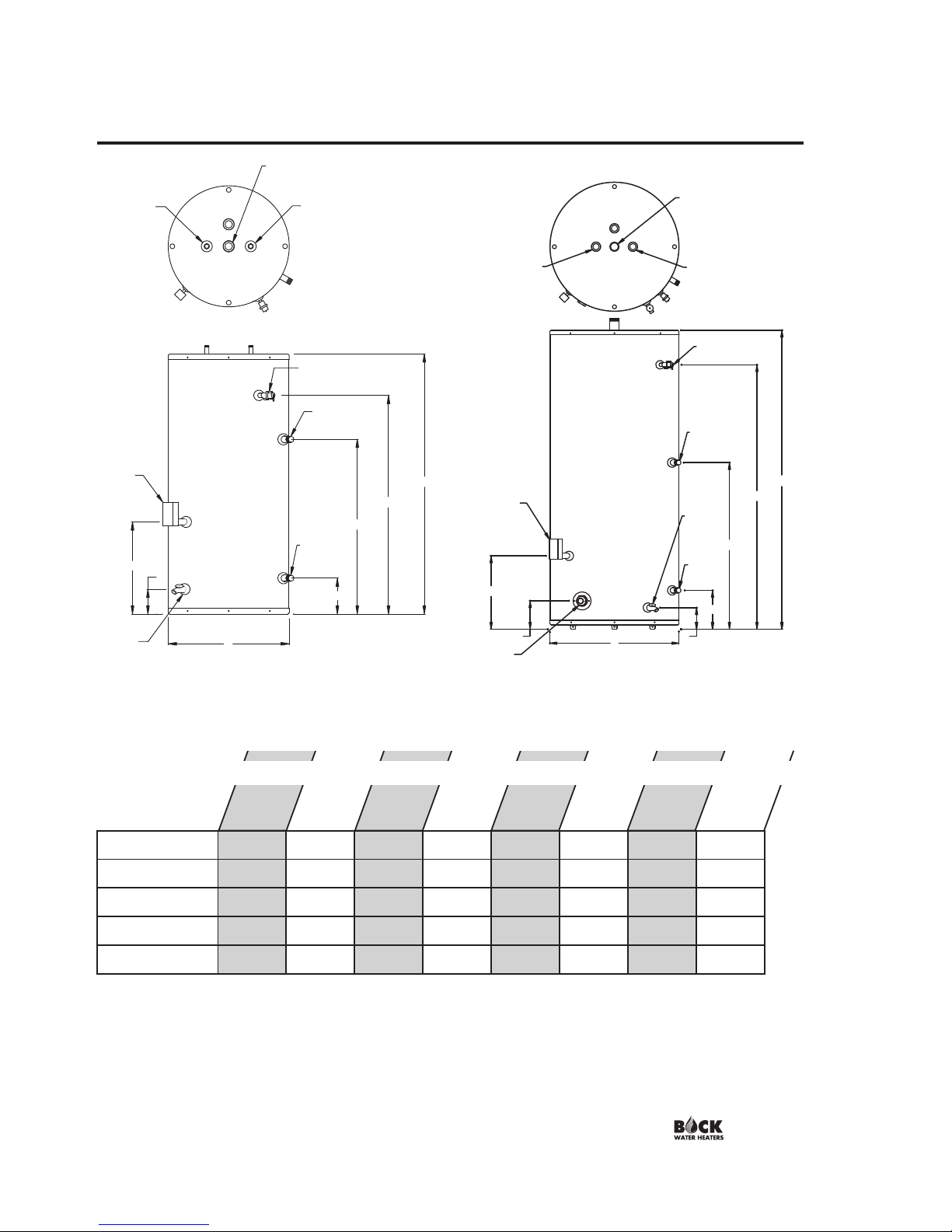
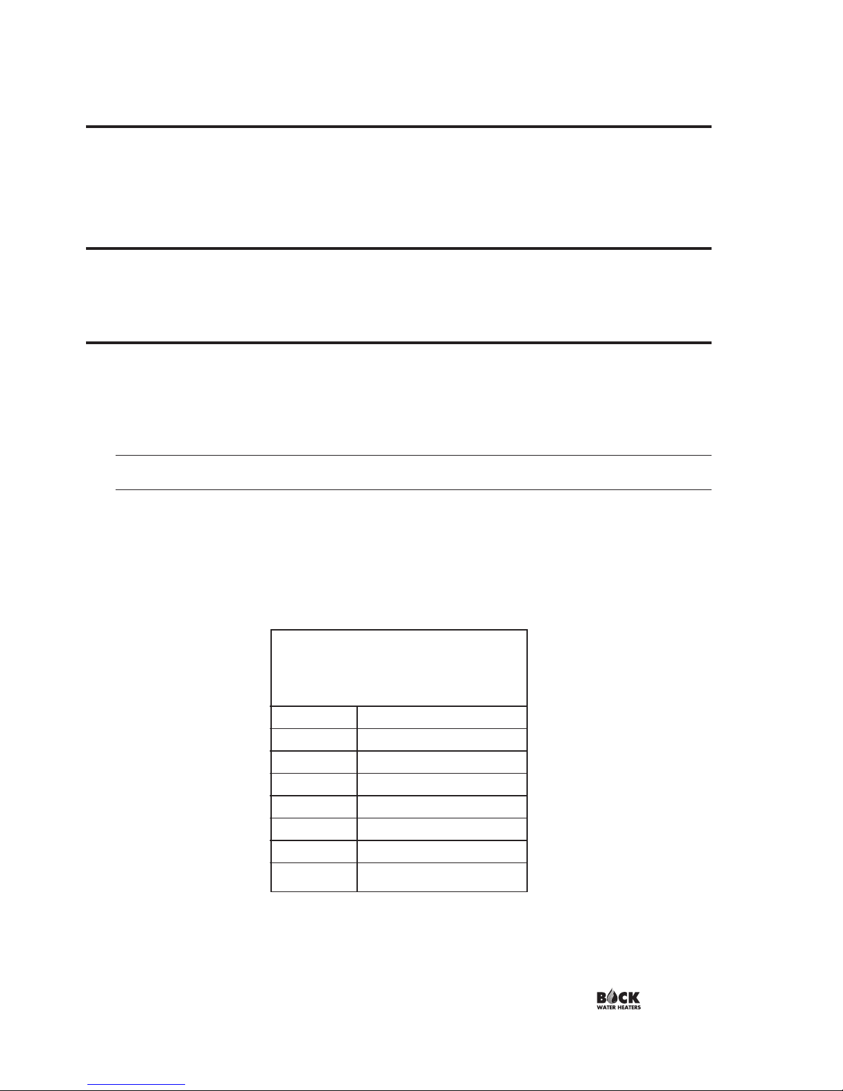
SECTION I: SPECIFICATIONS
Foam insulation standard on Indirect models. Pressures, all: Test pressure, 300 PSI Working pressure, 150 PSI
Standard voltage, all: 120V, 60Hz, 1P. T&P valve installed; nipples supplied for top connection.
WARNING: Installation should be in accordance with all national and/or local codes.
CAUTION: The recommended water temperature setting for normal residential use is 120°F. Bock recommends a tempering
valve or anti-scald valve be installed and used according to the manufacturer's directions to prevent scalding.
30SK
22
35 1⁄4 27 3⁄4 19 1⁄2 11 3⁄4 6 1⁄2 4 1⁄2 n/a
40SK 22 42 1⁄4 34 3⁄4 31 1⁄2 16 3⁄4 6 1⁄2 4 1⁄2 n/a
50SK 22 48 1⁄4 39 3⁄4 31 1⁄2 16 3⁄4 6 1⁄2 4 1⁄2 n/a
80SK 24 64 57 1⁄8 33 19 1⁄4 8 5 5
119SK 28 65 57 3⁄4 33 3⁄4 16 1⁄4 8 3⁄4 5 6 1⁄2
Model
A
B
C
D
E
F
G
H
Table 1: Dimensions
G
H
A
E
F
D
C
B
Cold Inlet,
1 1/2" NPT
Hot Outlet,
1 1/2" NPT
Anode
Rod
Anode
Rod
T&P Relief
Valve
From Boiler
Supply, 1" NPT
To Boiler
Return,
1"NPT
Drain
Valve
Aquastat
Figure 2: 80SK, 119SK
D i m e n s i o n s
Figure 1: 30SK, 40SK, 50SK
Page 4
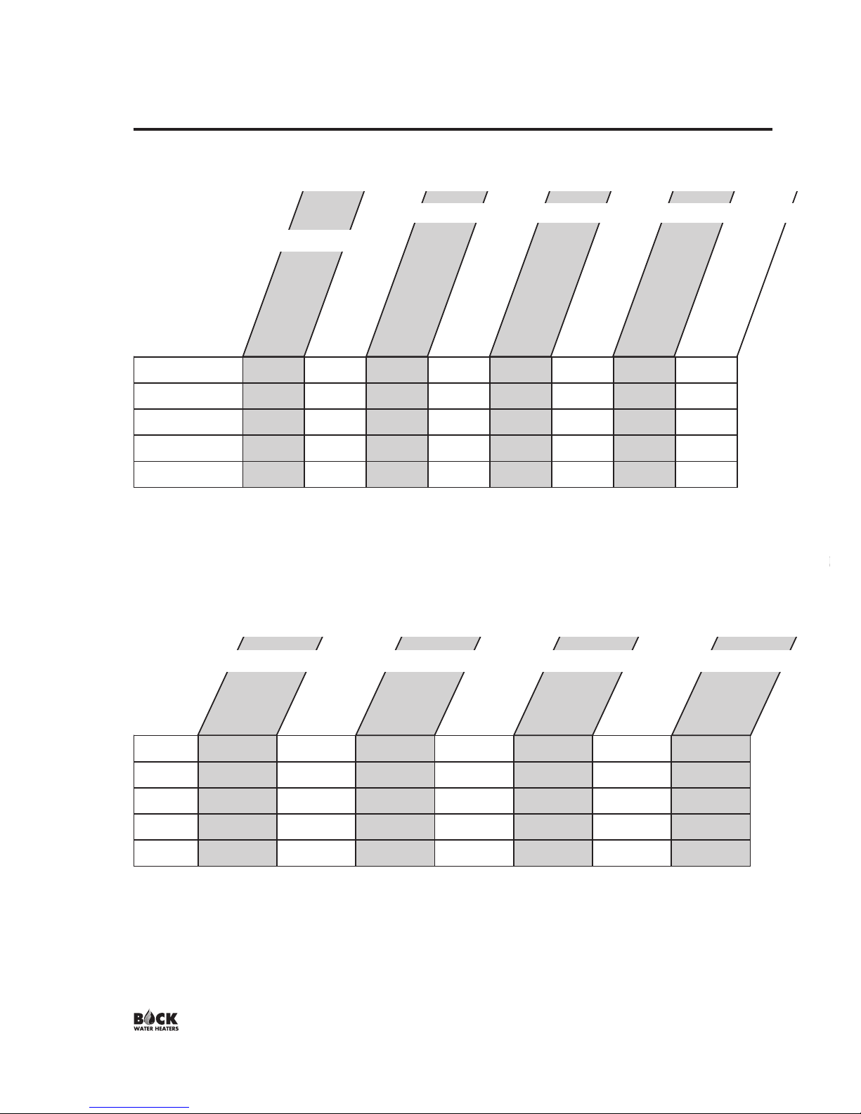
SECTION I: SPECIFICATIONS (cont.)
30SK 30 1.4 119 92 27 59,000 1.5 2.3
40SK 38 2.3 198 165 33 105,000 1.5 3.4
50SK 45 2.3 205 165 40 105,000 1.1 3.4
80SK 75 2.8 259 189 70 120,000 0.8 3.5
119SK 110 2.8 291 189 102 120,000 1.2 3.5
Model
Actual Tank
Volume (gal)
Coil Volume
(gal)
First Hour
Rating (gal)*
Continuous Draw
Rating (GPH)*
First Draw
Rating (gal)*
Minimum Coil
Output (BTU/Hr)**
Standby Loss
Rating (°F/hr)
Heat Source Friction
Loss (ft. w.c.)
Table 2: Capacity & Performance
Capacities
P e r f o r m a n c e
30SK
115 @ 56,000 117 @ 57,000 118 @ 58,000 138 @ 71,000 144 @ 75,000 149 @ 78,000 154 @ 81,000
40SK
173 @ 89,000 183 @ 96,000 191 @ 101,000 214 @ 115,000 226 @ 123,000 235 @ 129,000 243 @134,000
50SK
180 @ 89,000 190 @ 96,000 198 @ 101,000 221 @ 115,000 233 @ 123,000 242 @ 129,000 250 @134,000
80SK
233 @ 104,000 245 @ 111,000 254 @ 117,000 277 @ 132,000 292 @141,000 304 @ 149,000 314 @155,000
119SK
265 @ 104,000 277 @ 111,000 286 @ 117,000 309 @ 132,000 324 @ 141,000 336 @149,000 346 @155,000
Model
180°F
8 GPM*
180°F
10 GPM*
200°F
8 GPM*
200°F
12 GPM*
FIRST HOUR RATING (gal) @ Coil Output (Btu/hr)
Table 3: Performance (cont.)
NOTES:
* Based on 77°F rise with 58°F potable water inlet temperature at 14 GPM heat source flow rate. Heat source temperature was 180°F.
** Minimum Coil output based on continuous boiler operation over 30 minutes. See Section III for additional considerations.
All data obtained through testing in accordance with GAMA INDIRECT-FIRED WATER HEATER TESTING STANDARD IWH-TS-1_MARCH 2003
200°F
14 GPM*
200°F
10 GPM*
180°F
12 GPM*
NOTES:
First Hour Rating = First Draw + Continuous Draw
* Coil Input (temperature, flow rate). Ratings based on 77°F rise with 58°F inlet potable water.
All data obtained through testing in accordance with GAMA INDIRECT-FIRED WATER HEATER TESTING STANDARD IWH-TS-1_MARCH 2003
Page 5
SECTION II: GENERAL INFORMATION
LOCATION
The indirect water heater should be located in a central location to the piping system, as
close as practical to the boiler and in an area not subject to freezing temperatures. Leave
sufficient space for servicing and maintaining the heater.
Note: Long heating supply runs can lengthen recovery times.
WATER TREATMENT/FILTRATION
In areas where poor water conditions are suspected (i.e. lime, iron, and other minerals), it is
essential that the water be tested and appropriate action taken to prevent damage to the
indirect heater and ensure the quality of the water.
TEMPERATURE CONTROL
Water temperature from the heat source / boiler to the indirect water heater is controlled by
an immersion aquastat. This control operates the circulator, and provides limited control for
domestic hot water temperature. The proper temperature setting for domestic hot water use is
120°F/49°C. If hotter water is required a tempering device or anti-scald device must be
installed at the domestic hot water outlet of the heater or at the point of use.
CAUTION: Hot water in excess of 120°F
can cause scalding!
Bock recommends a tempering valve or anti-scald valve be installed and used according to
the manufacturer’s directions to prevent scalding. Many state and local codes now require
installation of these devices. The tempering valve or anti-scald valve will ensure potable
water temperatures at the desired set point with a higher degree of accuracy.
APPROXIMATE
TEMPERATURE/TIME
RELATIONSHIPS TO
SCALDING
120°F More than 5 minutes
125°F 1
1
⁄2 to 2 minutes
130°F About 30 seconds
135°F About 10 seconds
140°F Less than 5 seconds
145°F Less than 3 seconds
150°F About 1
1
⁄2 seconds
155°F About 1 second

Page 6
SECTION II: GENERAL INFORMATION (cont.)
ANODE RODS
The anode rod is used as a sacrificial element within the volume of the storage tank. The
purpose of the magnesium anode rod is to protect the inside of the tank against corrosion.
Anode rods should be inspected twice in the first year and at least yearly once a time interval
for inspection has been developed. Water conditions can influence the consumption rate of
the anode rods. Please see the Maintenance section of this manual for instructions on how to
change the anode rods in your Bock water heater.
CAUTION: Hydrogen gas is produced in a hot water system served by this heater that has not been used for
a long period of time (2 weeks or more). Hydrogen gas is extremely flammable. To reduce the risk of injury
under these conditions, it is recommended that the hot water faucet be opened for several minutes at the
kitchen sink before using any electrical appliance connected to the hot water system. When hydrogen is
present, there will probably be an unusual sound such as air escaping through the pipe as the water begins to
flow. There should be no smoking or open flame near the faucet at the time it is open (UL 174).
TEMPERATURE AND PRESSURE RELIEF VALVE (T&P)
The T&P valve is factory installed. A discharge drain tube must be installed (responsibility of
the installer) and shall terminate plain, not threaded, 6 inches above the floor drain. The
drain tube material must be approved for temperatures of 120°F or greater, and a pressure of
150 PSI or greater.
BACK-FLOW PREVENTER (CLOSED LOOP SYSTEM)
Some local municipal codes and ordinances require the use of these devices on potable
(domestic) water lines. Where back-flow preventers are required, it will be necessary to
install a thermal expansion tank (designed for used with potable water) in order to prevent
pressure build up in the indirect heater and associated piping, which could cause the T&P
valve to discharge. Follow the expansion tank manufacturer’s recommendations when
selecting a tank for your hot water system.
Note: Working pressure of the water heater is 150 PSI. Do not exceed 150 PSI.

Page 7
SECTION III: PRE-INSTALLATION
BOILER AND CIRCULATOR SIZING
The ratings published in this manual for your Bock indirect water heater can be obtained
through proper selection of boiler output and circulator capacity. As noted, the ratings in
Table 2 are based on a 77°F rise with 58°F potable water inlet temperature at a circulator
pump flow rate of 14 GPM. The boiler was set at 180°F. See Table 3 for additional first hour
ratings at pump flow rates of 8, 10, 12 and 14 GPM with 180°F and 200°F boiler water.
To determine the appropriate circulator for your system, follow these three steps:
1) Calculate the pressure drop of all straight pipe and fittings on the supply and return at the
desired flow rate.
2) Add the pressure drop from Step 1 to the pressure drop through the indirect coil tank
water heater coil (see Table 2 for friction loss) to obtain a total pressure drop.
3) Select a circulator pump that will provide adequate flow at the total pressure drop.
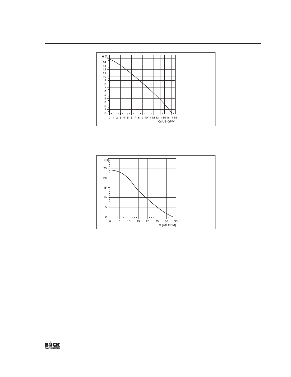
A pump performance curve should accompany every circulator pump. Figures 3-5 contain
performance curves for Taco and Grundfos circulator pumps, recommended by Bock.
Figure 3: Taco 00 Series performance curves
Page 8
UP 15-42F/FR
Closed Systems, 60 Hz
UP 26-64F
Closed Systems, 60 Hz
SECTION III: PRE-INSTALLATION (cont.)
Figure 4: GRUNDFOS UP 15-42F performance curve
Figure 5: GRUNDFOS UP 26-64F performance curve
Note: Zone valves on the heat source supply to the indirect heater are not recommended
and will drastically reduce performance.
System performance can also vary based on the heating capacity of the boiler. If the
minimum coil output (assume coil output = boiler output) listed in Tables 2 and 3 is not met,
the output (first hour rating) of the water heater will not be met at the selected flow rate.
To approximate the reduction in first hour rating as a result of low boiler capacity, use the
following formula:
New first hour rating = (First hour rating) * (Actual boiler output)/(Minimum coil output)
For example, the first hour rating of a 50SK at a 77°F rise with an 14 GPM heat source flow
rate using a boiler having a DOE heating capacity (output) of 60,000 BTU/Hr would be:
New first hour rating = (205 gal) * (60,000 BTU/Hr)/(94,000 BTU/Hr) = 131 gal

Page 9
BOILER
SUPPLY
SYSTEM
DOMESTIC
3/4"
HOT OUT
INDIRECT
WATER HEATER
BOILER
TO
BOILER
FROM
COLD
INLET
3/4"
VALVE
CHECK
PUMP
CIRCULATOR
RETURN
SYSTEM
BOILER
BOILER
1" NPT
1" NPT
BOILER
SYSTEM
SUPPLY
CIRCULATOR
PUMP
BOILER
SYSTEM
RETURN
BOILER
COLD
1 1/2"
INLET
WATER HEATER
INDIRECT
HOT OUT
DOMESTIC
1 1/2"
BOILER
FROM
TO
BOILER
CHECK
VALVE
1" NPT
1
1" NPT
1" NPT
Figure 7: 80SK, 119SK water connections
SECTION IV: INSTALLATION
WATER CONNECTIONS
All piping between the boiler and the indirect heater should be new copper with a
minimum size of 3/4” ID for models 30SK, 40SK, and 50SK. Use 1” minimum copper for
models 80SK and 119SK. Elbows should be minimized. A flow check valve must be
installed on the return line.
All piping to the inlet (cold) and outlet (hot) domestic water connections should be new
copper with a minimum size of 1/2” ID for models 30SK, 40SK, and 50SK. Use 3/4” ID
minimum for models 80SK and 119SK.
All piping should conform to local codes and ordinances. At a minimum, refer to IHLR 84
code if local codes are not in place. It is recommended that all piping be adequately
insulated with approved material to ensure minimum heat loss. If a re-circulation line is
used for domestic water, be certain that all lines are well insulated and the circulator is
temperature controlled. Install isolation valves to permit proper servicing. It is also
recommended to install a union on the domestic outlet to facilitate replacement of the hot
outlet / anode nipple on models 30SK, 40SK, and 50SK.
See Figures 6 and 7 for proper water connection installation.
Note: Indirect may be connected to a steam
boiler provided that all piping to and from
the boiler are below the water line of the boiler.
Boiler must also be protected by a low water
cut off safety device.
Figure 6: 30SK, 40SK, 50SK water connections
Page 10
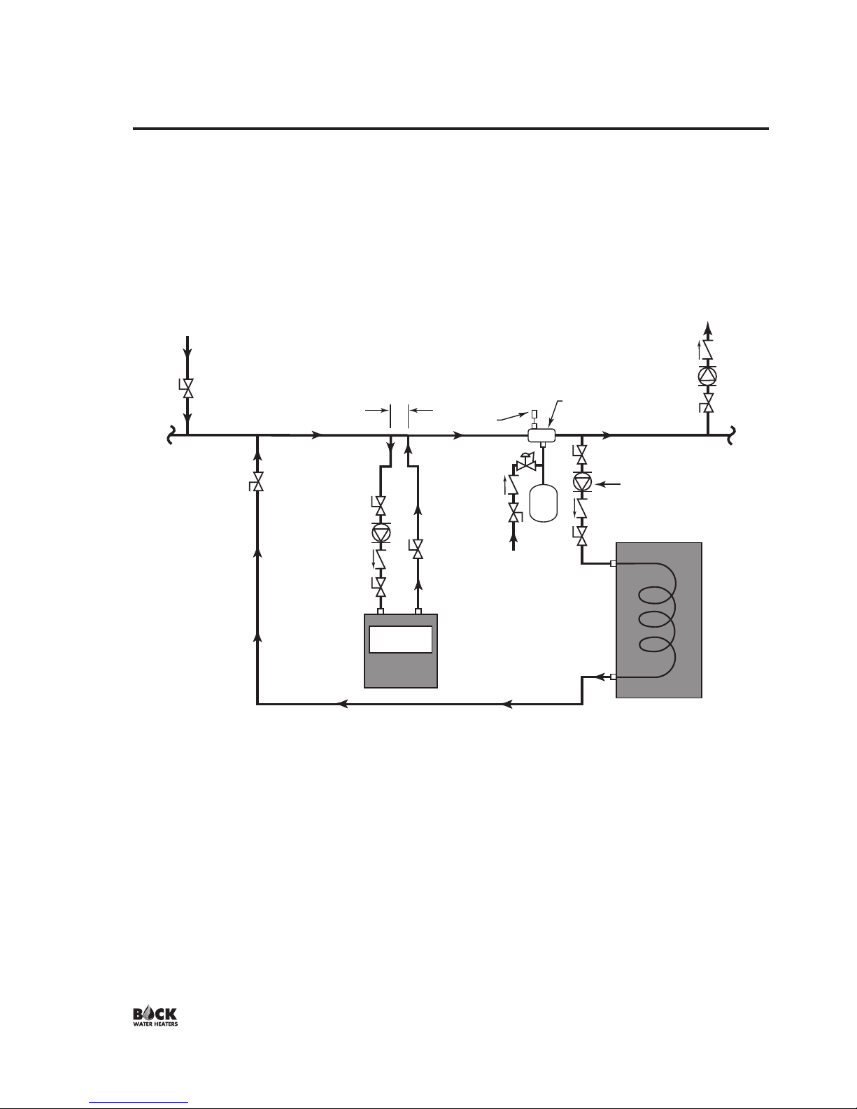
See Figure 8 for piping your Bock indirect water heater to a low-mass boiler (diagram
recommended by boiler manufacturer).
SECTION IV: INSTALLATION (cont.)
CHECK
VALVES
ZONE
CIRCULATORS
ISOLATION
VALVES
ADDITIONAL
ZONES
INDIRECT
CIRCULATOR
INDIRECT WATER
HEATER
TO
HEATING
ZONE
AIR
SEPARATOR
AIR VENT
EXPANSION
TANK
COLD
WATER
INLET
BOILER
CIRCULATOR
LESS THAN (4)
PIPE DIAMETERS
BOILER
FROM
HEATING
ZONE
ISOLATION
VALVES
ADDITIONAL
ZONES
Figure 8: Bock Indirect with Low-Mass Boiler
 Loading...