

Bob Long Victory User Manual

1/01/10
BOB LONG TECHNOLOGIES techsupport@boblongdirect.com
Mokelumne Hill, CA www.boblongdirect.com

CAUTION: READ ALL WARNINGS BEFORE USING OR ATTEMPTING ANY WORK ON YOUR
VICTORY. SHOULD YOU BE UNSURE AT ANY POINT, STOP AND SEEK PROFESSIONAL
SUPPORT.
CONTENTS
Contents ................................................................................................................................................................ 2
Warning ................................................................................................................................................................. 3
Warranty ................................................................................................................................................................ 3
Quick Start ............................................................................................................................................................. 4
Powering On Marker .......................................................................................................................................... 4
Installing Air Tank ............................................................................................................................................... 4
Turning Eyes On/Off ........................................................................................................................................... 4
Adjusting Velocity ............................................................................................................................................... 4
Adjusting the Trigger .............................................................................................................................................. 5
Removing/Replacing Trigger ............................................................................................................................... 5
Maintenance .......................................................................................................................................................... 6
Maintaining the Eyes and Detents....................................................................................................................... 7
Maintaining the HPR (In-Line-Regulator) ............................................................................................................. 8
Maintaining the LPR ........................................................................................................................................... 9
Setting HPR Pressure........................................................................................... Error! Bookmark not defined.
Setting Initial LPR Pressure ............................................................................................................................ 10
Setting Pressures if No Pressure Tester is Available ........................................................................................... 10
Setting Pressures Using the Pressure Tester ...................................................................................................... 11
Maintaining the Engine ..................................................................................................................................... 12
Removal of the ASA .......................................................................................................................................... 13
O-Rings and Fasteners .......................................................................................................................................... 14
O-Rin gs ............................................................................................................................................................. 15
O-Rin gs ............................................................................................................................................................. 16
Fasteners.......................................................................................................................................................... 17
Q & A ................................................................................................................................................................... 18

CAUTION: READ ALL WARNINGS BEFORE USING OR ATTEMPTING ANY WORK ON YOUR
VICTORY. SHOULD YOU BE UNSURE AT ANY POINT, STOP AND SEEK PROFESSIONAL
SUPPORT.
Troubleshooting Guide ......................................................................................................................................... 20
WARNING
This Paintball Marker is not a toy. Misuse may cause serious injury or
death. Eye protection designed specifically for Paintball must be worn by
user and any other persons within 200 yards (183 meters) of this Marker.
Must be at least 18 years old to purchase, at least 14 years old to use or
operate under adult supervision, 10 years of age or older to use or operate
on insured Paintball fields meeting ASTM-standard F1777-97. Read
owner’s manual prior to using or operating this Paintball Marker. .
WARRANTY
Bob Long Technologies warrants our paintball markers to be free from defect in materials and workmanship for a
period of 1 year from purchase date. This warranty will only be honored for the initial retail purchaser and is nontransferable. Wear items such as batteries and seals are not covered under warranty. Main PCB, electropneumatic solenoid, eye PCB’s and wire harnesses will be covered under warranty for a period of 6 Months from
purchase date.
This warranty does not cover:
> Any system failure resulting from the use of a non-authorized propellant. The only authorized propellants are
nitrogen or compressed air.
> Damage to electro-p ne u m a ti c s o l e n oi d resulting from external air source regulation failure. The use of an
external regulated air source is your choice, so research well and choose wisely.
> Damage to electro-pneumatic solenoid from foreign objects, specifically Teflon® tape.
> Surface damage such as scratches, nicks, or dings.
> Improper disassembly or re-assembly.
> Improper lubrication. The only authorized grease for maintaining a Bob Long marker is Molykote® 55 made by
the Dow Corning Corporation (Dow 55). Authorized oil is limited to Tri-flow® or any other synthetic oil made
specifically for maintaining a paintball marker.
> Modification or any other alteration of a marker or its parts. Dremels, acid, most things involving a show on the
Bravo network or HGTV fit in this category.
> M i su se of any conceivable kind. Basically if it involves law enforcement officers, the phrase “I hope we don’t get
caught!”, use as a pry bar, or other things that would have made it into an episode of the show Jackass.
This warranty is limited to repair or replacement of defective items with the initial retail purchaser to pay shipping
costs. The initial retail purchaser must enclose a copy of the original sales receipt with the marker to be repaired
for this warranty to be honored.
CAUTION: READ ALL WARNINGS BEFORE USING OR ATTEMPTING ANY WORK ON YOUR
VICTORY. SHOULD YOU BE UNSURE AT ANY POINT, STOP AND SEEK PROFESSIONAL
SUPPORT.
Quick Start
Installing Air Tank
Much like any other tournament marker, the Victor y requires the use of compressed air or nitrogen only. Use of a
low pressure compressed air system is recommended with each Bob Long marker. If using an adjustable-output air
system, set the system’s output to between 450 and 550 psi . Make sure the ASA (Air Source Adapter) is in the off
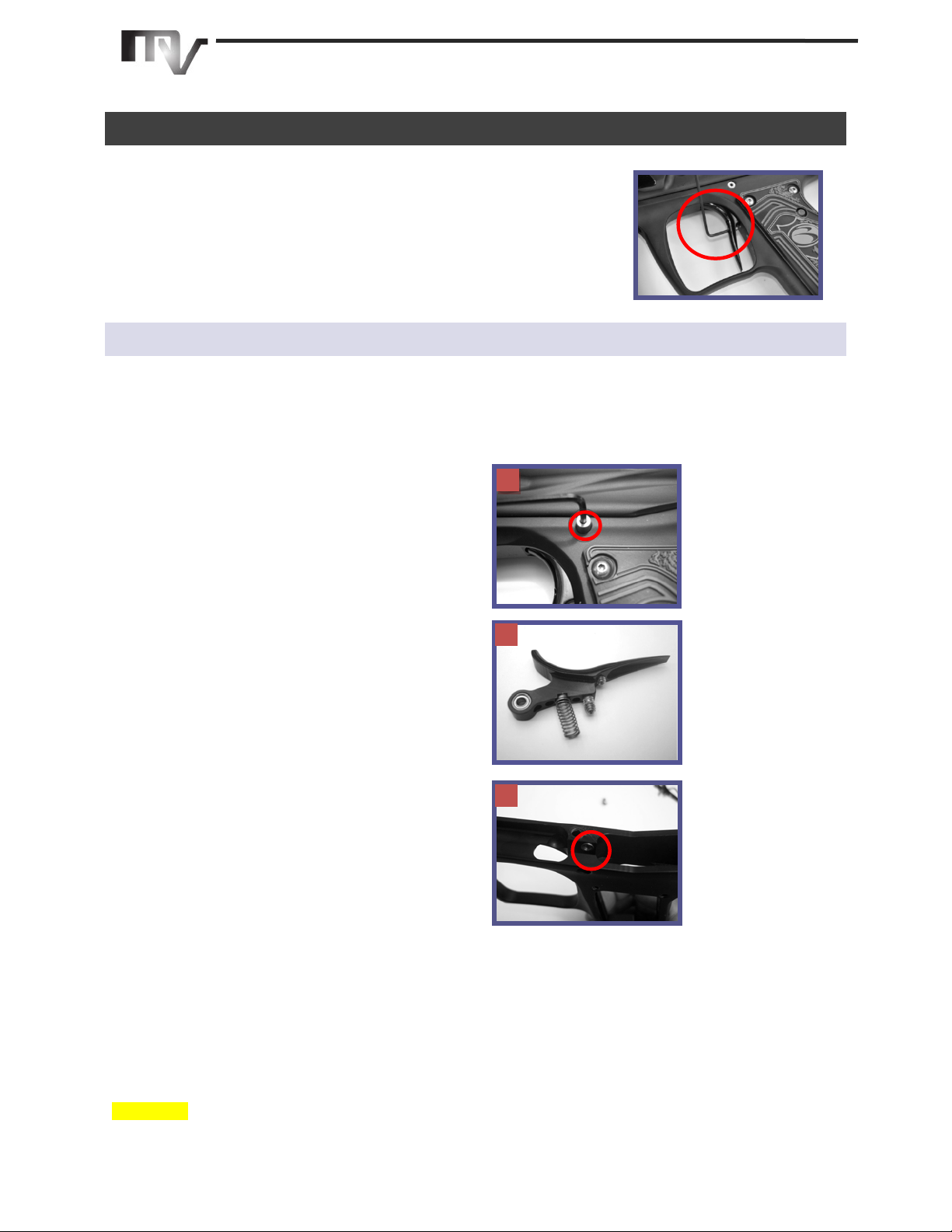
position by turning the chrome cam drive knob on the bottom of the ASA. Attach your compressed air tank by
screwing it into the ASA. When you are ready to chrono your marker turn the cam drive knob clockwise until it
completes turning – this is shortly after you hear air pressurizing the marker.
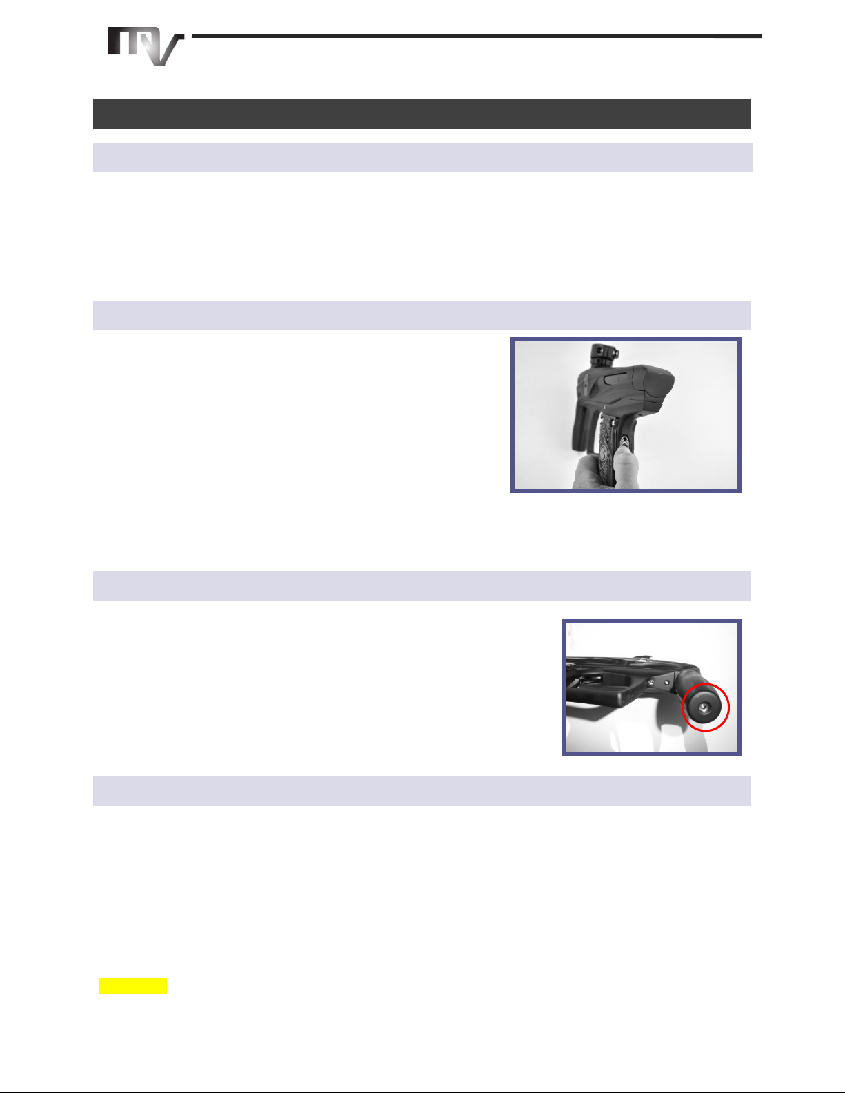
Powering On Marker
Press and release the power button on the back of the grip frame to
turn the marker on. T h e startup sequence has a battery indicator
w h i c h will show the current power level of your ba t t e r y w i t h a
flickering red, yellow, or green LED li g h t as the marker powers up. If
the LED is showing Red on startup replace the battery before using
your marker.
A ft er t he startup battery indication the LED will display a solid or
blinking blue light.
To power off marker: Press and hold the power button for 1.5 seconds, until the LED turns off, then release. Every
time the marker is turned on, the eyes are enabled. The marker can be turned off regardless of the state of the
eyes.
Adjusting Velocity
Both the High Pressure and Low Pressure regulators on the Victory come preset
from the factory. Prior to play you may need to adjust them to account for
paint to bore match, a t m o sp h e r i c d i f f e r en c e s , an d y o u r f i e l d ’s m a x i mu m
chronograph limit. The velocity of your marker is controlled through the H PR,
which is adjusted with a 1\8” hex w r e n ch .
Turning the screw clockwise (or inward) will increase your velocity; turning the
screw counterclockwise will decrease your velocity. Only turn the wrench 1/8th
-1/16th of a turn with each adjustment.
Turning Eyes On/Off
Each time the marker is turned on the eyes are enabled regardless of status when the marker was shut off. To
disable the eyes briefly press and release the power button when the marker is turned on. Briefly press it a second
time to re-enable the eyes.
CAUTION: READ ALL WARNINGS BEFORE USING OR ATTEMPTING ANY WORK ON YOUR
VICTORY. SHOULD YOU BE UNSURE AT ANY POINT, STOP AND SEEK PROFESSIONAL
SUPPORT.
Adjusting the Trigger
The Vic tory trigger has two adjustment screws. The bottom screw is for trigger
post-t ra v el and the top screw adjusts the activation point (where the marker
fires). To adjust the screws insert a hex key and turn the screw. The screws
have Loctite to prevent the adjustment from slipping, so a firm steady pressure
is needed for the adjustment.
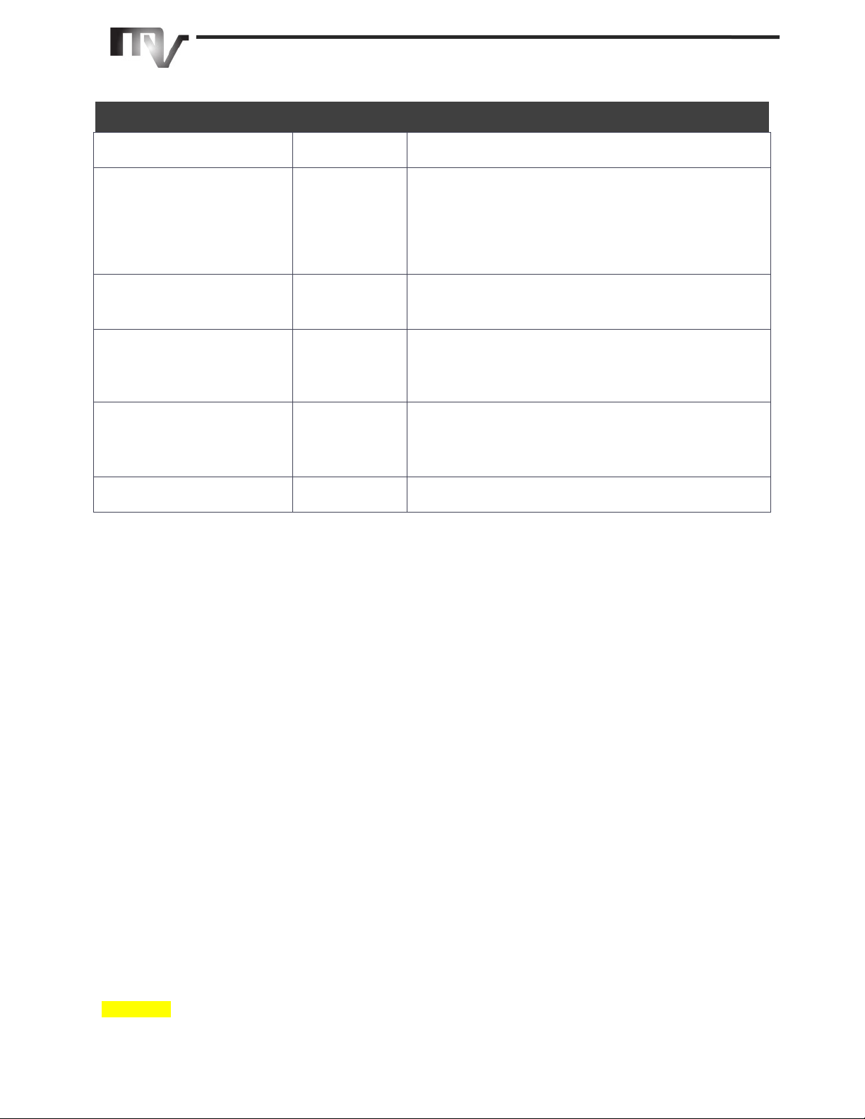
Removing/Replacing Trigger
For most operation and maintenance the t r i g ge r d o es n o t ne e d r em o v a l . If an aftermarket trigger is being
installed or debris enters the trigger area removal and cleaning may be necessary.
1. In order to remove the trigger us e a 5/64” hex
wrench to remove the trigger mounting screw.
The trigger will slide towards the front of the grip
frame when the mounting screw is removed. I f
you have any problems removing the trigger from
the front remove the grip frame then r em o ve t h e
trigger f r om t h e t o p.
2. The Victory trigger is a new design and is not
backwards compatible with Generation 1 Marqs.
The major difference with the new trigger is the
offset geometry to accommodate the grip frame’s
internal air channel.
3. Ensure that the bearing spacer is in the right side
of the grip frame when installing a trigger. T h e
picture to the right shows the position of the
spacer with the grip frame removed.
1
3
2
CAUTION: READ ALL WARNINGS BEFORE USING OR ATTEMPTING ANY WORK ON YOUR
VICTORY. SHOULD YOU BE UNSURE AT ANY POINT, STOP AND SEEK PROFESSIONAL
SUPPORT.
Maintenance
Amount of Time
Estimated Cases
of paint
R e c o m m e n d e d U p k e e p
While talking smack with your
friends in between games
• R e m ov i n g t he e n g i ne and barrel
• Run a c l e a n swab through the firing chamber i f
there is broken paint or debris in the chamber
• Put a drop of oil on the bolt o-rings if your friends
are still flapping their g u m s
• Reinstall engine
After a day of play
1-2 Cases
• Repeat above steps
• Wipe down marker outside
• Clean and lube bolt
After a Weekend
2-4 Cases
• Repeat above steps
• Clean and g re as e o u t s id e o f en g i n e
• Inspect o-r ings for damage
• Clean debris and old grease f r o m engine area
A Month
10 Cases
• Repeat above steps
• Clean, inspect, and g re as e HPR P i st o n o-ring
• Disassemble, clean, inspect, and gre ase a l l e ng i n e
o-rings
6 months or when consistency
issues appear
20+ Cases
• Clean, inspect, and g re as e LPR Piston and o-rings

CAUTION: READ ALL WARNINGS BEFORE USING OR ATTEMPTING ANY WORK ON YOUR
VICTORY. SHOULD YOU BE UNSURE AT ANY POINT, STOP AND SEEK PROFESSIONAL
SUPPORT.
Maintaining the Eyes and Detents
In the event of a chopped ball or debris in the breach, your Victory eyes may need cleaning.
1. Remove the eye cover screw using a 5/64” h e x
wr en ch, and remove the eye cover.
2. Remove the detent and spring by pressing on the
detent from inside the chamber.
3. Carefully unscrew the PCB retaining screw. (Phillips
head)
4. G e n tl y t i l t the eye PCB away from the body of the
m a r k e r.
5. Use a clean cotton swab to clean the surface of the
eye, the eye holes, detent and detent hole. Da m p e n
the swab with alcohol if necessary.
6. If removing the eyes from the wiring harness unplug
the harness from the eye PCB by pulling on the white
plug and not the wires. Pu l l i ng o n t he w i r e s c o u l d
potentially damage your harness.
7. Af ter th e e ye , detent, and mounting area h a v e been
sufficiently cleaned, reinstall the PCB and reinstall
the PCB retaining screw and eye cover.
• The 4C eye system will allow for higher rates of
fire through quicker cycling times.
• To determine whether the 4C eyes are installed
refer to the picture at the bottom left. Th e 4 C
eyes have more components as well as the
number 4 silk screened onto the PCB.
• The standard Delrin detents can be replaced
with t h e S u pe r D s - a n u pg r a d e d Ty p e I II
anodized detent. If the Super D s are used the
sides of the detents must be greased slightly.
Also, the S u pe r D s must be rotated slightly each
time the eyes are cleaned in order to ensure
even wear.
1
2
3
4
5
6
 Loading...