


 Loading...
Intimidator |
Long Technologies |
G6R |
|
Bob |
|
|
|
|
Bob Long Technologies 209-293-4440 www.boblongdirect.com
CAUTION: READ ALL WARNINGS BEFORE USING OR ATTEMPTING ANY WORK ON YOUR MARKER. SHOULD YOU BE UNSURE AT ANY POINT, STOP AND SEEK PROFESSIONAL SUPPORT.

|
2 |
Table of Contents |
|
Warning .................................................................................................................................................................................................. |
3 |
Warranty ................................................................................................................................................................................................ |
3 |
Introducing the G6R ......................................................................................................................................................................... |
4 |
Ready for the Field.................................................................................................................................................................. |
4 |
Trigger Adjustment and Maintenance.................................................................................................................................... |
5 |
Maintaining the Eyes and Detents ............................................................................................................................................ |
6 |
Maintaining the HPR (In-Line-Regulator)............................................................................................................................. |
7 |
Maintaining the LPR......................................................................................................................................................................... |
8 |
Setting Pressures Using the Pressure Tester ...................................................................................................................... |
9 |
Maintaining the bolt ...................................................................................................................................................................... |
10 |
Maintaining the Ram..................................................................................................................................................................... |
10 |
Maintaining the Poppet Valve .................................................................................................................................................. |
11 |
Accessing the Poppet............................................................................................................................................................... |
11 |
Cleaning the Poppet and Reassembly ............................................................................................................................. |
12 |
Grip Frame Removal ..................................................................................................................................................................... |
13 |
O-Rings and Fasteners ................................................................................................................................................................. |
14 |
O-rings............................................................................................................................................................................................. |
14 |
Fasteners........................................................................................................................................................................................ |
15 |
O-Ring Size Table....................................................................................................................................................................... |
16 |
Q&A........................................................................................................................................................................................................ |
17 |
Troubleshooting Guide ................................................................................................................................................................ |
19 |
CAUTION: READ ALL WARNINGS BEFORE USING OR ATTEMPTING ANY WORK ON YOUR MARKER. SHOULD YOU BE UNSURE AT ANY POINT, STOP AND SEEK PROFESSIONAL SUPPORT.

3
Warning
This paintball marker is not a toy. Misuse or mishandling can result in serious injury or death. Every person within range of a loaded paintball gun must wear eye protection specifically designed for paintball. It is recommended at least 18 years of age to purchase, 14 years old to use with adult supervision or 10 years old to use on paintball fields meeting ASTM standards F1777-97. Ensure you read the entire instruction manual before operating your marker.
BobWarrantyLong Technologies warrants our paintball markers to be free from defect in materials and workmanship for a period of 1 year from purchase date. This warranty will only be honored for the initial retail purchaser and is non-transferable. Wear items such as batteries and seals are not covered under warranty. Main PCB, electro-pneumatic solenoid, eye PCB’s and wire harnesses will be covered under warranty for a period of 6 Months from purchase date.
This warranty does not cover:
> Any system failure resulting from the use of a non-authorized propellant. The only authorized propellants are nitrogen or compressed air.
> Damage to electro-pneumatic solenoid resulting from external air source regulation failure. The use of an external regulated air source is your choice, so research well and choose wisely.
> Damage to electro-pneumatic solenoid from foreign objects, specifically Teflon® tape. > Surface damage such as scratches, nicks, or dings.
> Improper disassembly or re-assembly.
> Improper lubrication. The only authorized grease for maintaining a Bob Long marker is Molykote® 55 made by the Dow Corning Corporation (Dow 55). Authorized oil is limited to Triflow® or any other synthetic oil made specifically for maintaining a paintball marker.
> Modification or any other alteration of a marker or its parts. Dremels, acid, most things involving a show on the Bravo network or HGTV fit in this category.
> Misuse of any conceivable kind. Yes, letting a hipster use your marker may damage your warranty.
This warranty is limited to repair or replacement of defective items with the initial retail purchaser to pay shipping costs. The initial retail purchaser must enclose a copy of the original sales receipt with the marker to be repaired for this warranty to be honored.
CAUTION: READ ALL WARNINGS BEFORE USING OR ATTEMPTING ANY WORK ON YOUR MARKER. SHOULD YOU BE UNSURE AT ANY POINT, STOP AND SEEK PROFESSIONAL SUPPORT.

4
TheIntroducingsixth generationthe G6RIntimidator platform, G6R, brings new advances to the stacked tube poppet valve marker. These advances include the front/rear split body and internally routed, macroline free air channels. The front/rear split enables more choices in milling, internal air routing, and weight reduction than standard one piece designs. Internally routed air channels prevent the failures possible in macroline systems and allow more hand positioning options for YOU when switching hands. The G6R is designed, machined, and built in the USA.
WhileReady thefor theG6RFiseldtournament ready out of the box, certain components may be upgraded for increased performance.
|
Stock |
Available Upgrade |
Feedneck
Control Board
Eyes
Bolt
Amount of Time |
Estimated |
|
Recommended Upkeep |
|
Cases of paint |
|
|
your friends in between |
|
• |
Run a clean swab through the firing chamber |
|
•• |
||
games |
|
|
|
|
|
|
Put a drop of oil on the bolt o-rings if your |
|
|
• |
friends are still failing to get on the field |
|
|
• |
Reinstall bolt |
|
|
•• |
Wipe down marker outside |
|
|
• |
Clean and oil bolt |
|
|
•• |
Remove the Ram Cap and Ram |
|
|
|
Clean debris and old grease from ram |
|
|
• |
interior |
|
|
• |
Inspect o-rings for damage |
|
|
• |
Clean and grease ram |
consistency issues appear |
|
• |
Clean, inspect, and grease HPR Piston o-ring |
|
• |
||
|
• |
Clean, inspect, and grease poppet shaft o- |
|
|
|
|
ring |
CAUTION: READ ALL WARNINGS BEFORE USING OR ATTEMPTING ANY WORK ON YOUR MARKER. SHOULD YOU BE UNSURE AT ANY POINT, STOP AND SEEK PROFESSIONAL SUPPORT.

5
TheriggerG6R comesAdjustmentwith a rollerandbearingMaintenancetrigger which you can adjust for the feel which is most comfortable with your style of play. To simplify maintenance the trigger can be removed from the marker without requiring the removal of the grip frame.
1.The G6R has two adjustment screws. The bottom screw is for trigger posttravel and the top screw adjusts the activation point (where the marker fires). To adjust the screws insert a hex key and turn the screw. The screws have Loctite to prevent the adjustment from slipping so a firm, steady pressure is needed for the initial adjustment.
2.To remove the trigger begin by removing the trigger pivot pin
3.If the trigger spring encounters resistance when partially removed it may be catching on the micro switch of the control board. Simply push up on the spring with a hex key and it will slide free.
4.Use swabs dipped in alcohol to clean any residual paint or grime from the trigger area. If necessary open the grip panels and clean inside the frame as well.
5.When reinstalling the trigger press up on the spring slightly to prevent snagging the microswitch.
CAUTION: READ ALL WARNINGS BEFORE USING OR ATTEMPTING ANY WORK ON YOUR MARKER. SHOULD YOU BE UNSURE AT ANY POINT, STOP AND SEEK PROFESSIONAL SUPPORT.

6
In the event of a chopped ball or debris in the breach, the eyes in your G6R may need cleaning. The |
||||||||||||
Maintai ing the Eyes nd D tents |
||||||||||||
most common ways for debris to enter the ball chamber is through the hopper when using a rapid/ |
||||||||||||
speed feed type system. Tournament grade balls may break in the stack if the loader applies too |
||||||||||||
much pressure. |
||||||||||||
1. Remove the eye cover screw using a 5/64” |
|
|
|
|
|
|
|
|
|
|
||
hex wrench, then remove the eye cover. |
|
|
|
|
|
|
|
|
|
|
||
|
|
|
|
|
|
|
|
|
|
|||
2. Remove the detent and spring by pressing on |
|
|
|
|
|
|
|
|
|
|
||
the detent from inside the chamber. |
|
|
|
|
|
|
|
|
|
|
||
3. Carefully unscrew the PCB retaining screw. |
|
|
|
|
|
|
|
|
|
|
||
(Phillips head) |
|
|
|
|
|
|
|
|
|
|
||
4. Gently tilt the eye PCB away from the body of |
|
|
|
|
|
|
|
|
|
|
||
the marker. |
|
|
|
|
|
|
|
|
|
|
||
|
|
|
|
|
|
|
|
|
|
|||
5. Use a cotton swab to clean the surface of the |
|
|
|
|
|
|
|
|
|
|
||
|
|
|
|
|
|
|
|
|
|
|||
eye, the eye holes, detent and detent hole. |
|
|
|
|
|
|
|
|
|
|
||
Dampen the swab with alcohol if necessary. |
|
|
|
|
|
|
|
|
|
|
||
NOTE: If removing the eyes from the wiring |
|
|
|
|
|
|
|
|
|
|
||
harness unplug the harness from the eye PCB |
|
|
|
|
|
|
|
|
|
|
||
|
|
|
|
|
|
|
|
|
|
|||
|
|
|
|
|
|
|
|
|
|
|||
by pulling on the white plug and not the |
|
|
|
|
|
|||||||
wires. Pulling on the wires could potentially |
|
|
|
|
|
|||||||
|
||||||||||||
damage your harness. |
|
|
|
|
|
|||||||
6. After the eye, detent, and mounting area have |
|
|
|
|
|
|||||||
been sufficiently cleaned, reinstall the PCB |
|
|
|
|
|
|||||||
and reinstall the PCB retaining screw and eye |
|
|
|
|
|
|||||||
cover. |
|
|
|
|
|
|||||||
• |
The 4C eye system will allow for higher rates |
|
|
|
|
|
|
|
|
|
|
|
|
|
|
|
|
|
|
|
|
|
|
||
• |
of fire through quicker cycling times. |
|
|
|
|
|
|
|
|
|
|
|
|
To determine whether the 4C eyes are |
|
|
|
|
|
|
|
|
|
|
|
|
installed refer to the picture to the right. The |
|
|
|
|
|
|
|
|
|
|
|
|
4C eyes have more components as well as the |
|
|
|
|
|
|
|
|
|
|
|
• |
number 4 silk screened onto the PCB. |
|
|
|
|
|
|
|
|
|
|
|
|
The standard Delrin detents can be replaced |
|
|
|
|
|
|
|
|
|
|
|
|
with Super Ds - an upgraded Type III |
|
|
|
|
|
|
|
|
|
|
|
|
anodized detent set. If Super Ds are used, the |
|
|
|
|
|
|
|
|
|
|
|
|
sides of the detents must be greased lightly. |
|
|
|
|
|
|
|
|
|
|
|
|
Also, Super Ds must be rotated slightly each |
|
|
|
|
|
|
|
|
|
|
|
|
time the eyes are cleaned in order to ensure |
|
|
|
|
|
|
|
|
|
|
|
|
even wear. |
|
|
|
|
|
|
|
|
|
|
|
|
|
|
|
|
|
|
|
|
|
|
|
|
CAUTION: READ ALL WARNINGS BEFORE USING OR ATTEMPTING ANY WORK ON YOUR MARKER. SHOULD YOU BE UNSURE AT ANY POINT, STOP AND SEEK PROFESSIONAL SUPPORT.
7
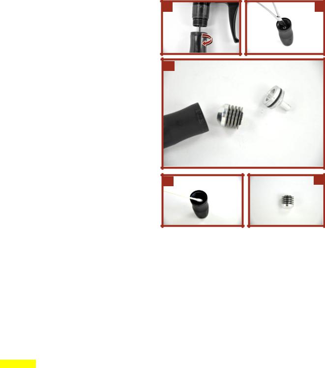
YourMaintainingG6R comestheequippedHPR (Inwith-Linethe-bestRegulator)regulators on the market. To ensure the highest consistency and the maximum flow possible, we recommend that you clean and lubricate them according to the maintenance schedule or whenever you encounter inconsistency. The regulators typically perform flawlessly for many cases of paint before requiring any maintenance.
1. Degas the marker and ensure that there are no paintballs in the breech or barrel of the marker.
2. Unscrew the bottom half of the regulator from the marker. Note that the top half is factory tightened and should not be removed.
3. Reach into the regulator base with tweezers or needle nose pliers to remove the regulator piston.
4. After the piston is removed turn the regulator base upside down and tap the spring stack and spring follower into your hand. The picture to the right shows the regulator body, spring stack, and piston.
5. The main valve located in the top portion of the regulator which is still connected to the marker does not need to be removed from the marker body or serviced. Never replace or attempt to service a working main valve.
6. Inspect the surface of the piston and piston o-ring for excessive wear or nicks and replace as necessary.
7. Inspect the interior walls of the regulator base. Use a swab on the interior of the regulator base to clean debris and old grease.
8. When reassembling the spring follower (spring stack assembly) make sure that the top and bottom spring washers curve to the outside. A close up of the spring assembly with the retaining o-ring is shown to the right. The retaining o-ring does not require lubrication
If in doubt – just stack the spring washers like this:
)()()()(
CAUTION: READ ALL WARNINGS BEFORE USING OR ATTEMPTING ANY WORK ON YOUR MARKER. SHOULD YOU BE UNSURE AT ANY POINT, STOP AND SEEK PROFESSIONAL SUPPORT.
Loading...