


Bob Long Intimidator
2002 . Dragon . Ripper
Owners Manual |
August 2002 |
TABLE OF CONTENTS |
|
Section |
Page |
Safety .............................................................................................................. |
2 |
Warranty ......................................................................................................... |
3 |
History (theory of operation)....................................................................... |
3 |
General Description...................................................................................... |
4 |
Specifications................................................................................................ |
4 |
Operation......................................................................................................... |
8 |
Gas Configurations....................................................................................... |
8 |
CO2 ............................................................................................................................................ |
8 |
Preset HPA/Nitrogen ............................................................................................................... |
8 |
Adjustable HPA/Nitrogen ........................................................................................................ |
8 |
Ammunition Aspects.................................................................................... |
8 |
Hopper ....................................................................................................................................... |
8 |
Paint............................................................................................................................................ |
8 |
Regulators...................................................................................................... |
9 |
Low Pressure Regulator.......................................................................................................... |
9 |
High Pressure Regulator ......................................................................................................... |
9 |
Optional Expansion Attachment............................................................... |
10 |
Electronics................................................................................................... |
10 |
Battery Information................................................................................................................. |
10 |
Anti Chop Eye ......................................................................................................................... |
10 |
Light Emitting Diode (LED)/Liquid Crystal Display (LCD)................................................ |
11 |
Mode Selection ....................................................................................................................... |
11 |
DIP Switch Settings ............................................................................................................... |
15 |
Disassembly/Assembly.............................................................................. |
16 |
Trigger Disassembly .............................................................................................................. |
16 |
Regulator Disassembly ......................................................................................................... |
19 |
Body Disassembly.................................................................................................................. |
21 |
Maintenance................................................................................................. |
24 |
General .................................................................................................................................... |
24 |
Regulator ................................................................................................................................. |
24 |
Consumables .......................................................................................................................... |
24 |
Troubleshooting.......................................................................................... |
25 |
BOB LONG GZ INTIMIDATOR – PAGE 1

Congratulations on your purchase of the Intimidator paintball marker. The Intimidator represents the latest in paintball marker technology at a very affordable price. Before operating your Intimidator, please read the entire manual carefully.
WARNING
This paintball marker is not a toy. Misuse or mishandling can result in serious injury or death. Every person within range of a loaded paintball gun must wear eye protection specifically designed for paintball. Recommended at least 18 years of age to purchase, 14 years old to use with adult supervision or 10 years old to use on paintball fields meeting ASTM standards F1777-97. Ensure you read entire instruction manual before operating your Intimidator.
SAFETY
Please follow all local, state, and federal laws concerning the operation and use of
paintball markers. By purchasing this paintball marker you assume all liability.
B.L.A.S.T. assumes no liability for injury or death due to misuse or mishandling of this
marker.
qNever point a paintball marker at anyone not wearing paintball-approved goggles. Even at the lowest possible operating velocity, a paintball will cause serious injury should it hit someone in the eye area.
qNever look down the barrel of your marker with or without wearing paintball approved goggles.
qBefore performing any maintenance on the marker, ensure air source is disconnected and marker has been dry fired.
qLeave the ON/OFF switch in the OFF position whenever marker is not operational.
qAlways insert barrel plug in barrel when marker is not operational. Remove only in designated operational areas.
qOnly play at commercial playing fields that have a chronograph, referees, and clearly marked safe areas. Chronograph your marker before each game to ensure marker is operating at a safe velocity. Safe velocity is considered to be 280 feet per second (fps).
BOB LONG GZ INTIMIDATOR – PAGE 2

WARNING
Make sure marker is not shooting at a dangerous velocity. Ensure all participants are wearing the proper paintball safety equipment. You will be held liable if someone is hurt by a paintball fired from your marker regardless of fault.
WARRANTY
B.L.A.S.T. warrantees the Intimidator against damages in manufacturing and defects. Electrical components are warranted for a period of 90 days. Wire harnesses located within the grip frame will only be warranted against manufacturing defects. When utilizing aftermarket Drop-Forwards ensure attachment bolts DO NOT protrude into internal grip assembly. When utilizing aftermarket Grips ensure attachment bolts DO NOT protrude into internal grip assembly. Failure to do this will result in void of warranty.
For questions concerning your Intimidator manual please call (925) 625-7929.
HISTORY (THEORY OF OPERATION)
The Intimidator marker is a solenoid controlled open-bolt design, very similar to the popular open-bolt blowback design found in the Spyder. The primary difference is that instead of a blowback re-cocking on a spring-loaded striker, the bolt is locked into a dual pressurized machined slider. The back of the chamber is pressurized to move the bolt forward, and the front is pressurized to move the bolt backward. This allows for very
low cycling pressure, as well as much less cocking recoil. An electronic 4-way valve controls this slider.
BOB LONG GZ INTIMIDATOR – PAGE 3

GENERAL DESCRIPTION
The marker includes dual regulators. Both regulators are mounted on the front of the
Intimidator body assembly, with standard 3/8-in. hex key velocity adjustments. The high-pressure regulator is mounted at the top front of the regulator base and maintains the firing rate of the Intimidator. The low-pressure regulator, which is mounted directly below the regulator base, maintains the cycling rate. All functions are electronically controlled via a circuit board and 4-way air valve. Settings are changed via a 2-button, internally lit Liquid Crystal Display (LCD) screen. Rates of fire are variable from 8.1 to 14 balls per second (bps), firing modes are from semi auto, full auto, 3 shot burst, 6 shot burst, turbo, reactive, and test. Located within the marker body is a pair of infrared anti chop eyes. The anti chop eye consists of a set of sensors mounted in the bottom of the breach to restrict firing until the ball has completely loaded in the breach. The trigger is fully adjustable with adjustments for spring tension; pull restriction, and firing pull. The gun will perform on CO2 or HPA/Nitro (factory recommended). The Intimidator comes stock with a two-piece Bob Long barrel.
SPECIFICATIONS
Model............................................................................................................................... |
Intimidator |
Caliber.......................................................................................................................................... |
68 |
Action................................................................................................................. |
Electro-Pneumatic |
Power (air) ................................................. |
CO2 or Compressed Air/Nitrogen (recommended) |
Power (electronics) ................................................................................................. |
9-Volt Battery |
Cycle Rate .................................................................................... |
up to 14 paintballs per second |
Effective Range .............................................................................................................. |
150+ feet |
Weight ........................................................................................................... |
2 pounds, 10 ounces |
Length ...................................................................................................... |
(14” barrel) 22.5 inches |
|
(10” barrel) 19 inches |
Height ............................................................................................................................ |
10.5 inches |
BOB LONG GZ INTIMIDATOR – PAGE 4
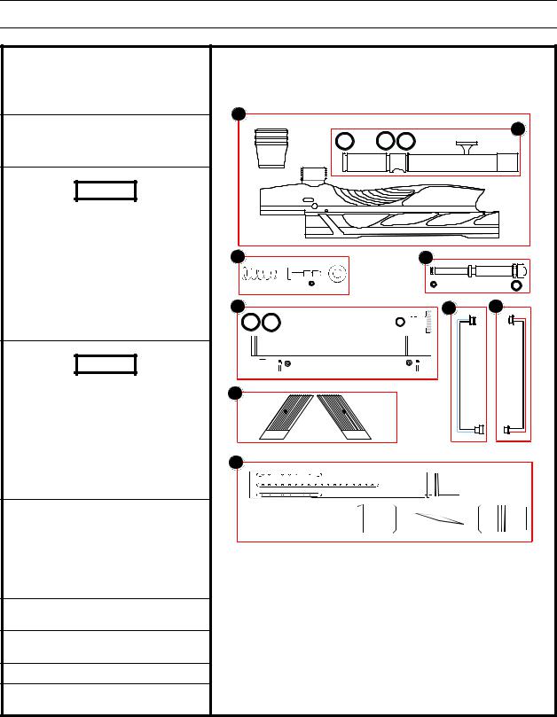
MARKER COMPONENTS
1.Body Assembly
qFeed Tube (attached w/black max)
qBody
qDecoration Block
2. Bolt Assembly
qBolt
q3 x 015 O-Rings
WARNING
Grease Poppet Assembly every 2000 to 3000 rounds fired. Doing this will reduce cup seal wear. DO NOT use lightweight oil as lubricant.
3. Poppet Assembly
qCone Shaped Spring
qPoppet
q1 x 004 O-Ring
qCup Seal
WARNING
Grease Ram Assembly every 2000 to 3000 rounds fired. Doing this will reduce O-ring wear. DO NOT use lightweight oil as lubricant.
4. Ram Assembly
q1 x 006 O-Ring
q1 x 011 O-Ring
qRam
5. Ram Sleeve
q2 x 015 O-Ring
q1 x 011 O-Ring
qSleeve Cap
q2 x Barbs w/fiber washers
qRetaining Allen
6.Left Eye Sensor Harness w/female connector
7.Right Eye Sensor Harness w/male connector
8.Left/Right Eye Covers
9.Barrel Assembly (2 piece J&J)
Body Assembly
1
2
015
3 |
4 |
|
004 |
006 |
011 |
5 |
6 |
7 |
015 |
011 |
|
8
9
BOB LONG GZ INTIMIDATOR – PAGE 5
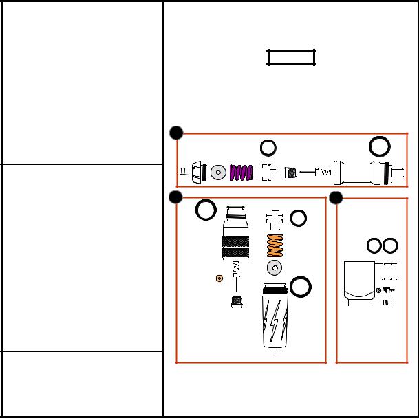
1.High Pressure Regulator
q3/16 Allen (velocity adjustment)
qRegulator Housing
q1 x 016 O-Ring
qSpring Base (washer)
qSpring (orange)
q1 x 113 O-Ring
qPiston
q1 x 010 O-Ring
qPin Valve Base (brass)
q1 x 006 Teflon O-Ring
qPin Valve
qPin Valve Spring
2.Low Pressure Regulator
q3/16 Allen (velocity adjustment)
qBottom Regulator Housing
q1 x 016 O-Ring
qSpring Base (washer)
qSpring (Orange)
qPiston
q1 x 113 O-Ring
q1 x 016 O-Ring
qTop Regulator Housing
qPin Valve Spring
qPin Valve
q1 x 006 Teflon O-Ring
q1 x 010 O-Ring
qPin Valve Base (brass)
3. Regulator Base
q2 x 015 O-Ring
q1 x Barb w/fiber washer
qBase
qBase Retaining Allen
Regulator Assembly
WARNING
Grease Regulator Piston every 2000 to 3000 rounds fired. Failure to do this will result in excessive Regulator Housing wear.
1 |
113 |
016 |
 010
010  006 Teflon
2 |
016
006 Teflon
010 
3 |
113
015
016
BOB LONG GZ INTIMIDATOR – PAGE 6

1.Trigger Frames
qRight Side Trigger Frame
qNameplate Cover (Backside of pictured)
qTrigger Guard
qTrigger
qTrigger Adjusters and Spring
qLeft Side Trigger Frame
qLCD Cover w/Push Buttons
qGrip
2.LCD Screen
WARNING
DO NOT use lightweight oil on marker. Oil will destroy internals of Air Valve.
3.Air Valve
qAir Valve w/male Connector (green/black wires)
4.12 Point Harness
qRight Eye Sensor w/female Connector
qLeft Eye Sensor w/male Connector
qLCD Screen Selection Membrane Male Connector
5.14 Point Harness
qConnection to 9-Volt Battery
qConnection to ON/OFF Switch
qConnection to Indicator Light
qConnection to Trigger Solenoid
qAir Valve Female Connector
6.Circuit Board
WARNING
Ensure gun air is disconnected and gun is discharged before making any mechanical adjustments to marker internals or electronics.
|
Trigger Assembly |
1 |
2 |
|
3 |
4 |
|
5 |
|
6 |
|
BOB LONG GZ INTIMIDATOR – PAGE 7

OPERATION
GAS CONFIGURATIONS
CO2
When operating the Intimidator on CO2 it is strongly recommended to use a form of the following:
qHigh Flow Expansion Chamber
qCO2 specific Regulator
qBottom Line w/tilt
qAnti-Siphon Tank
qRemote with Harness Mounted Tank
Preset HPA/Nitrogen
When utilizing a preset HPA/Nitrogen system it is best to use the optional expansion attachment (reference expansion attachment Conversion). Failure to do this will result in the over pressurization of the o-rings. Factory recommendations are 500 psi to the regulators. As most presets are around 800 to 850 psi output pressure, therefore the use of an external regulator is recommended. This transforms the highpressure regulator into an expansion chamber. Now the main high-pressure regulation falls on the vertical regulator.
Adjustable HPA/Nitrogen
This is the factory recommended means of airflow for markers not utilizing optional expansion attachment. By setting the output pressure to 500 psi satisfies the air requirement for the marker and does not allow over pressurizing of the o-rings.
AMMUNITION ASPECTS
Hopper
The Intimidator requires a high flow of paintballs to make full use of its features. To satisfy this the use of the motorized loaders are recommended.
Paint
Using top grade paint ensures the utmost in performance and accuracy.
BOB LONG GZ INTIMIDATOR – PAGE 8
 Loading...