

Page 1
Aftersales Training Product Information.
E92 M3 Complete vehicle.
BMW Service
www.Bimmerfest.com
Page 2

The information contained in the Product Information and the Workbook form an integral part of
the training literature of BMW Aftersales Training.
Refer to the latest relevant BMW Service information for any changes/supplements to the
Technical Data.
Information status: 07/2007
conceptinfo@bmw.de
© 2007 BMW Group
München, Germany. Reprints of this publication or its parts require the written
approval of
BMW Group, München.
VS-12 Aftersales Training
www.Bimmerfest.com
Page 3
Product Information.
E92 M3 Complete vehicle.
The 4th Generation M3
The integrated overall M concept
The S65B40 engine with 8 cylinders and
exceptional high engine-speed concept
www.Bimmerfest.com
Page 4

Notes on this product information
Symbols used
The following symbols are used in this product information to facilitate
better comprehension and to draw attention to important information.
3 Contains information to facilitate better understanding of the
described systems and their function.
1 Identifies the end of a note.
Information status and national variants
BMW vehicles conform to the highest safety and quality standards.
Changes in terms of environmental protection, customer benefits and
design render necessary continuous development of systems and
components.Consequently, this may result in deviations between this
product information and the vehicles available in the training course.
This document describes only EURO variants of left-hand drive vehicles.
Some controls or components may be arranged differently in right-hand
drive vehicles from the way shown on the graphics in the product
information. Further differences may arise as the result of the equipment
variants used in specific markets or countries.
Additional sources of information
Further information on the individual subjects can be found in the
following:
- Owner's Handbook
- BMW diagnostic system
- Workshop systems documentation
- SBT BMW Service Technology.
www.Bimmerfest.com
Page 5
Contents.
E92 M3 Complete vehicle.
Models
M3 Models 1
Introduction 3
Foreword 3
History 4
M3 concept 6
Competitor comparison 15
System overview 17
Vehicle electrical system/terminal status 17
MDrive 20
System components 25
Body/Interior trim and equipment: 25
S65B40O0 Engine 41
MSS60 Engine Control System 63
Drive train 73
Chassis and suspension 82
1
Service information 99
M3 concept 99
S65B40O0 Engine 100
MSS60 Engine control system 101
Drive train 102
Chassis and suspension 103
www.Bimmerfest.com
Page 6

www.Bimmerfest.com
Page 7

5
Models.
E92 M3 Complete vehicle.
M3 Models
Four Generations of the M3
EU Models E30 E36 E46 E92
M3 Coupé
2.3
(Evo. I)
Year 86-91 1990 92-95 1995 95-00 01-06 2003 07-
4 cyl.
Engine model
S14B23
Coupé
2.5
Evo. III
4 cyl.
S14B25
Coupé
3.0
6 cyl.
S50B30
Coupé
3.0
GT
6 cyl.
S50B30
Coupé
3.2
6 cyl.
S50B32
Coupé
3.2
6 cyl.
S54B32O0
Coupé
3.2
CSL
6 cyl.
S54B32T0V8S65B40O0
Coupé
4.0
Cylinder capacity
3
]
[cm
Power
[hp/kW] 200/147 238/175 286/210 295/217 321/236 343/252 360/265 420/309
At engine speed
[rpm]
max.
Power [hp/kW]
per litre 87/64 96/70 96/70 99/73 100/74 105/77,3 111/ 82 105/77.3
Torque [Nm]
At engine speed
[rpm] 4750 4750 3600 3900 3250 4900 4900 3900
EU weight*
[kg]
DIN power to
weight ratio
[kg per hp/kW] 6.0/8.2 5.0/6.9 5.1/7.0 4.9/6.7 4.5/6.2 4.4/5.9 3.9/5.2 3.8/5.1
Accel.
0-100 km/h [s]
1000 m** [s] 27.2 26.7 25.6 25.5 24.7 24.2 23.5 23.3
V
[km/h] 235 248 250*** 250*** 250*** 250*** 250***
max
2302 2467 2990 2990 3201 3246 3246 3999
6750
>7000
240 240 320 323 350 365 370 400
1275 1275 1535 1535 1535 1570 1460 1655
6.7 6.5 6.0 5.9 5.5 5.2 4.9 4.8
7000
> 7000
7000
7280
7000
7280
7400
7600
7900
8000
7900
8000
(280)
8300
8400
250*** (280)
* unladen weighton-the-road, with 75kg load,
fuel tank 90 % full, no optional equipment
** standing start
www.Bimmerfest.com
*** electronically controlled down/limited
(in brackets: increase in option V
max
)
1
Page 8

5
Comparison with E46 M3 and E92 335i
EU Models E92 M3 E46 M3 E92 335i
Coupé Coupé Coupé
Year 07- 01-06 07Engine model V8
S65B40O0
Cylinder capacity [cm3] 3999 3246 2979
Power [hp/kW] 420/309 343/252 306/225
At maximum
speed [rpm]
8300
8400
6 cyl.
S54B32O0
7900
8000
6 cyl. series
N54B30U0
5800
7000
Power [bhp/kW] per litre 105/77.3 105/77.3 102.7/75.5
Torque [Nm] 400 365 400
At engine speed [rpm] 3900 4900 1300-5000
EU weight*[kg] 1655 1570 1600
DIN power to weight ratio
[kg per hp/kW] 3.8/5.1 4.4/5.9 5.0/6.8
Acceleration
0-100 km/h [s]
1000 m** 23.3 24.2 24.5
V
[km/h] *** 250 (280) 250 250
max
* unladen weighton-the-road, with 75kg load,
fuel tank 90 % full, no optional equipment
** standing start
*** electronically controlled down/limited
(in brackets: increase in option V
4.8 5.2 5.5
).
max
2
www.Bimmerfest.com
Page 9
6
Introduction.
E92 M3 Complete vehicle.
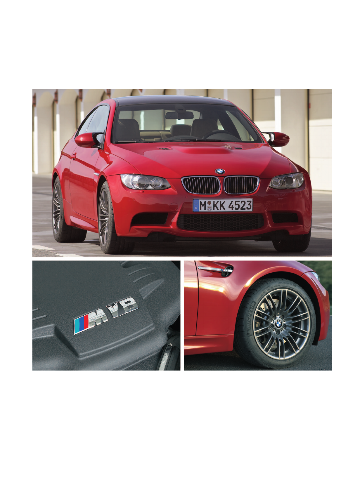
Foreword
A new addition to the ’M’ family has just
arrived. The new BMW M3.
A simple letter andnumbercombinationwhich
has become synonymous with an extremely
powerful and dynamic performance car.
The M3 is now in its fourth generation with a
history of success in the world of motor sport,
winning races across the globe since its
beginning back in 1985. Not only has the race
version of the M3 gained a successful motor
sports heritage, its on road credentials live up
to the expectations and demands of today’s
M3 drivers. The E92 M3 will be launched in
the middle of 2007.
This preciselybalanced sportscar will set new
benchmarks in driving dynamics for sport
coupes. As with its predecessor the focus has
been on optimizing the power to weight ratio
whilst maintaining the high engine speed
concept. This combination ensures that both
power and driving agility are exceptional,
placing the M3 in an even higher level of sport
car competition.
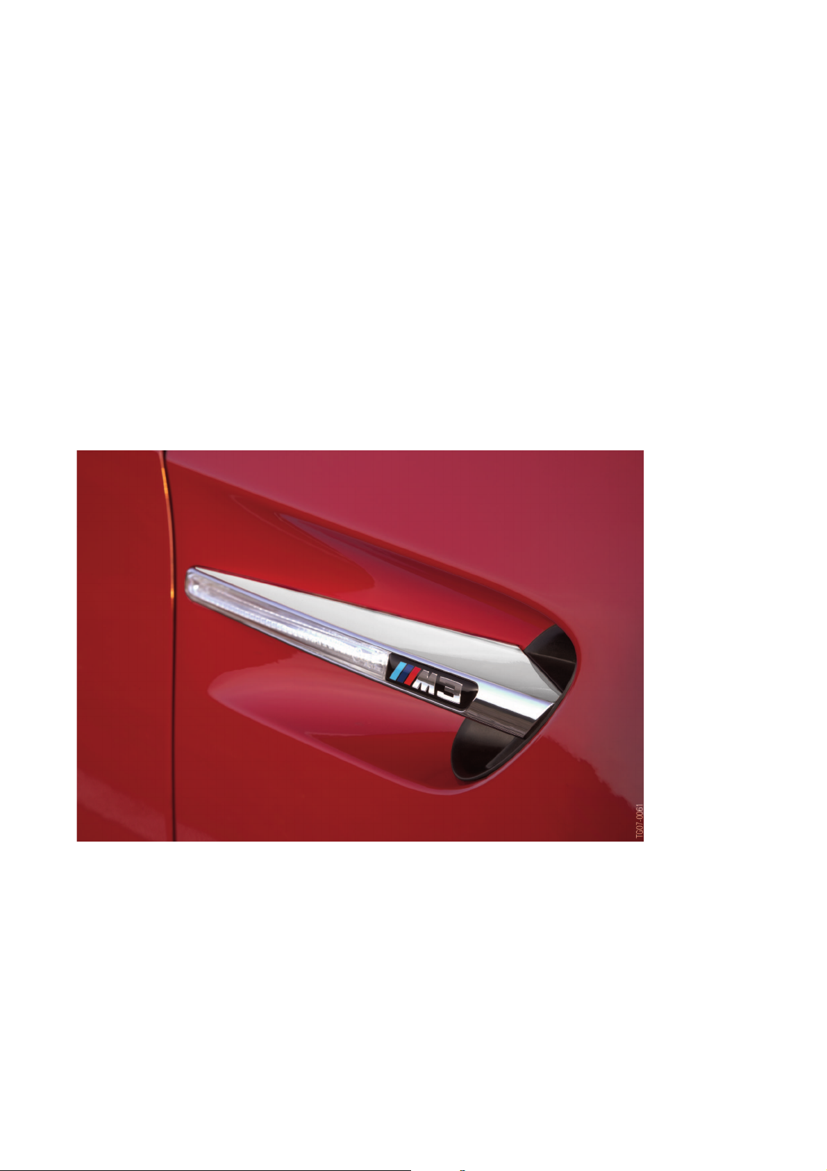
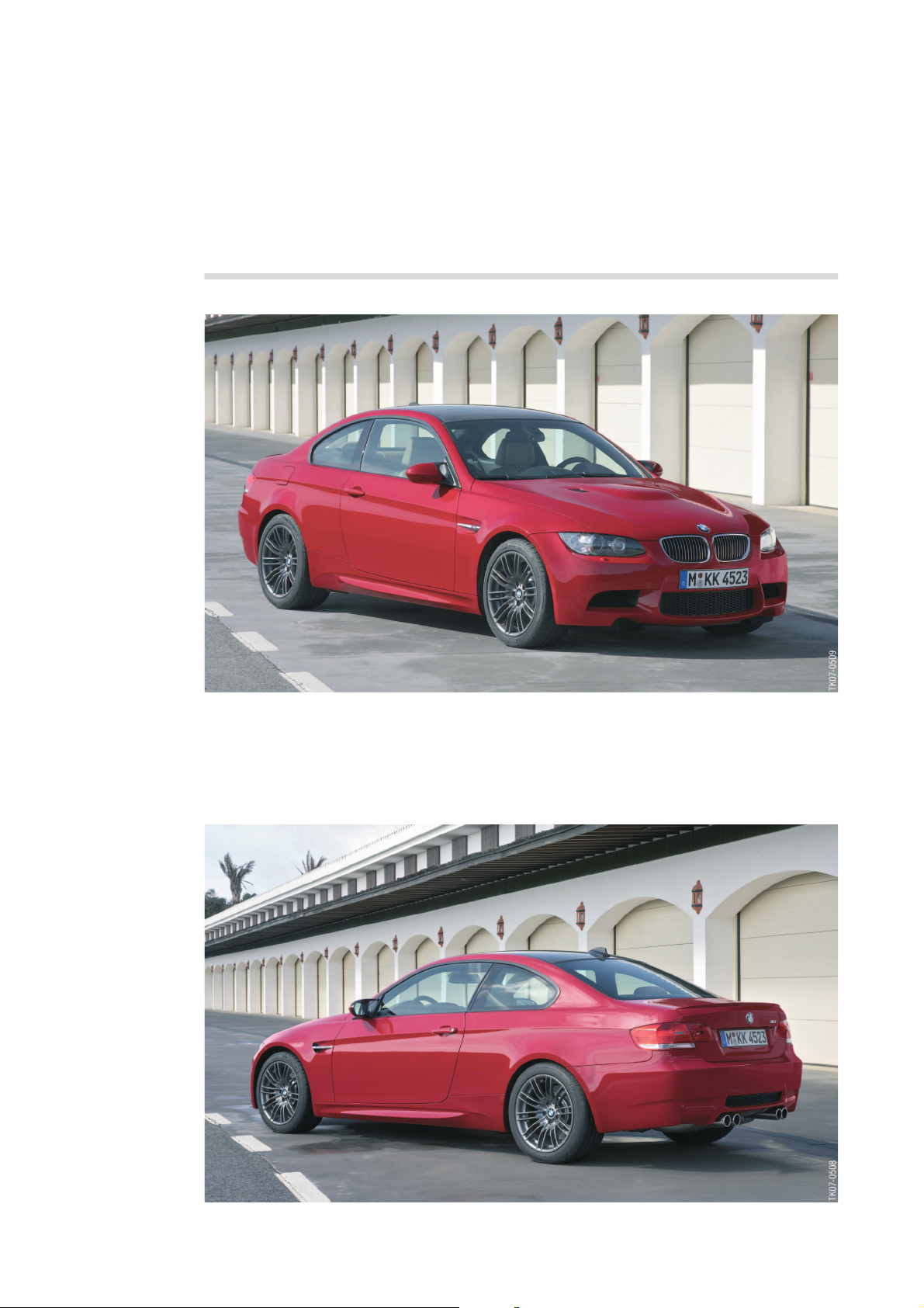
1 - E92 M3 side panel
3
www.Bimmerfest.com
Page 10
6
History
E30 M3
Approx. 18,000 vehicles delivered,
Coupé and Convertible. Two engines
worldwide.
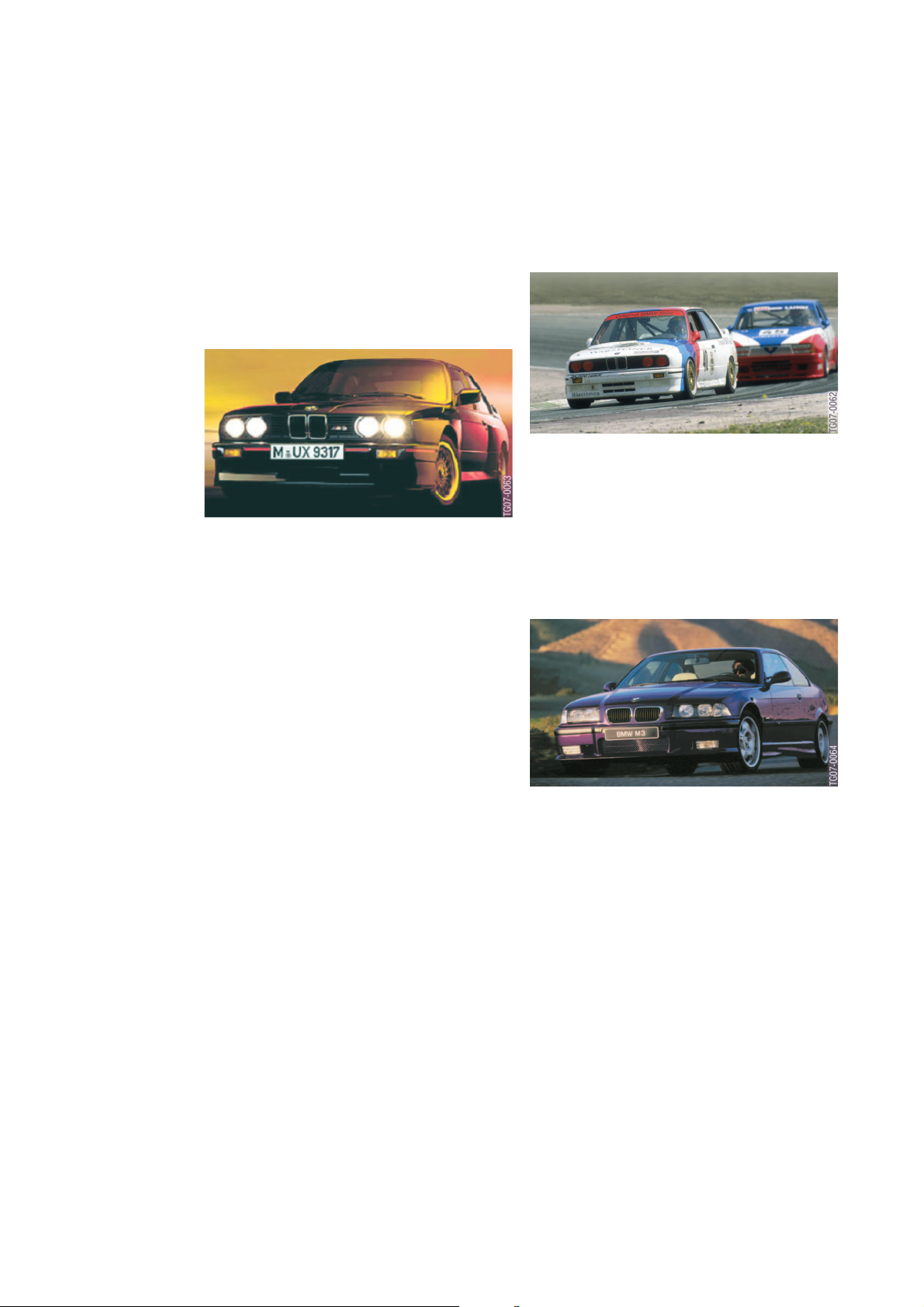
3 - The E30 M3 Cecotto takes part in the German Touring Car
Championships.
2 - E30 M3
1986
The E30 M3 celebrates its launch with a 4cylinder engine (S14B23) and 194/200 hp,
with/without catalytic converter.
1987
The M3 dominates touring car racing on the
world’s race tracks. Roberto Ravaglia brings
the World Championship title back to Munich.
The limited edition Evo I with 200 hp
(S14B23) arrives.
1988
The sought-after Evo II now features 220 hp
(S14B23).
Those who prefer ’open-top’ driving can
choose the M3 Convertible.
1989
The M3 wins 16 national and European titles,
including the European mountain
championship for touring cars.
The special edition Cecotto with 215 hp
(S14B23) makes its debut.
1990
The M3 is awarded 15 international and
national titles.
The limited number of Evo IIIs with catalytic
converter and 238 hp (S14B25) are quickly
snapped up.
E36 M3
Over 70,000 vehicles; Coupé,
Convertible and Saloons are produced,
not including the Z3 M Roadster and Z3
M Coupé. The M3 is available with two
different engines and vehicle
configurations; one for the EU, and
another for US release.
4 - E36 M3
1992
The second M3 generation, the E36 M3 with
6-cylinder engine and 286 hp (S50B30/US
S52B30 with 240 hp) causes a stir, the
individual version makes its worldwide debut
at the Geneva Motor Show. The highpressure VANOS variable camshaft control
(single VANOS) is used for the first time in an
M engine.
1993
The E36 M3 is now also available as a
Convertible.
1994
Steve Soper, Joachim Winkelhock and
Johnny Cecotto win the touring car world
championship.
A 4-door saloon model of the E36 M3 is
offered for the first time.
The homologation series of the M3 GT
(Coupé only) develops 295 hp (S50B30).
4
www.Bimmerfest.com
Page 11
6
1995
The E36 M3 European model is completely
upgraded. For example, it now features, a
compound brake with brake discs made from
compound materials, and high-pressure
double VANOS, enabling the engine
(S50B32) to reach 321 hp (US release
S52B32 still has 240 hp). The model remains
available only as a Coupé and a Convertible.
1996
The E36 M3 is made available with sequential
M transmission (SMG I).
E46 M3 Over
80,000 vehicles delivered, Coupé and
Convertible. One worldwide engine.
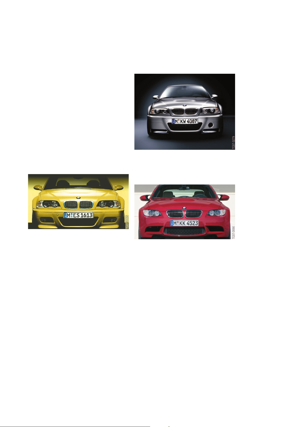
5 - E46 M3
2000
The third generation, the E46 M3 has a 6cylinder engine with a high engine speed
concept and 343 hp (S54B32). This first M
"high engine speed concept" engine
impresses the automotive experts and earns
the "Engine of the Year" award. The M3
becomes the first M vehicle to be delivered
with fully variableM limited slipdifferential with
up to 100 percent lock effect as a standard
feature.
2001
The M3 Convertible combines the fascination
of M power with the fun of open-top driving.
The 2nd generation sequential M
transmission (SMG II) is available.
2002
With the M3 CSL which produces 360 hp
(S54B32HP), the BMW M shows how a highperformance vehicle can be optimized still
further through the use of lightweight
construction materials in an intelligent
lightweight design. The M track mode (now
known as M dynamic mode), SMG Launch
Control (automatic upshift in S mode shortly
before maximum speed), and an electronic
ATF level are all used for the first time.
6 - E46 M3 CSL
E92 M3
The Coupé era begins. One worldwide
engine.
7 - E92 M3
2007
The fourth generation of the M3 arrives
featuring the S65B40 high-speed 8-cylinder
engine.
www.Bimmerfest.com
5
Page 12
6
M3 concept
8 - E92 M3 (Diagonal view from front)
• Body
In addition to the sporty and dynamic
appearance in both the external design and
the interior, the main features were weight
optimization and a reinforced bodyshell for
improved dynamic handling.
A further outstandingfeature of the E92M3
is also once again the sophisticated
aerodynamics typical of the M series.
9 - E92 M3 (Diagonal view from rear)
6
www.Bimmerfest.com
Page 13

6
• M-specific equipment
Exterior:
Front zone with generous air inlets,
"Powerdome" engine hood with air inlet,
carbon roof, side gills, outside mirrors, sill,
wheel rim design, extended wheel arches,
and the boot with spoiler and four exhaust
tailpipes all combine to provide the initial
impression.
Interior:
Sill trim strips, seats, steering wheel,
instrument cluster, switches in the centre
console and the gear lever design all
increase the anticipation.
• Engine
Under the engine hood, the 8-cylinder
power pack is the high-speed S65B40.
With individual throttle butterflies, a
generous intake air and exhaust manifold,
and many more refined M-specific features
such as the MSS60 engine control, the
S65B40 is once again an outstanding
highlight of the M series.
• Drive
Double-disc clutch, 6-gear manual
transmission and the fully variable M
limited-slip differential ensure the forward
momentum.
• Chassis and suspension
Front and rear axles with new suspension
geometry and M-specific suspension
settings with 18" tyres.
Specific objectives of the development
were weight optimization, and in particular,
control of the longitudinal and lateral
acceleration/power that is generated when
enjoying the pleasure of driving the M3.
The M3 brake with compound brake discs,
new high-performance brake pads and
standard M series ABS/DSC guarantee
optimum braking efficiency and active
safety.
• Electrical system
The electrical equipment and bus structure
of the M3 are based on the E92.
The optional MDrive menu can be used to
preset/configure the standard Servotronic
and the M engine dynamics control
(enhanced with "Sport Plus"), the optional
electronic damper control EDC-K (in the
E9x series only available in the M3) and the
DSC M dynamic mode.
In the E9x series, the BMW Individual High
End audio system isofferedfor the first time
in the M3.
www.Bimmerfest.com
7
Page 14
6
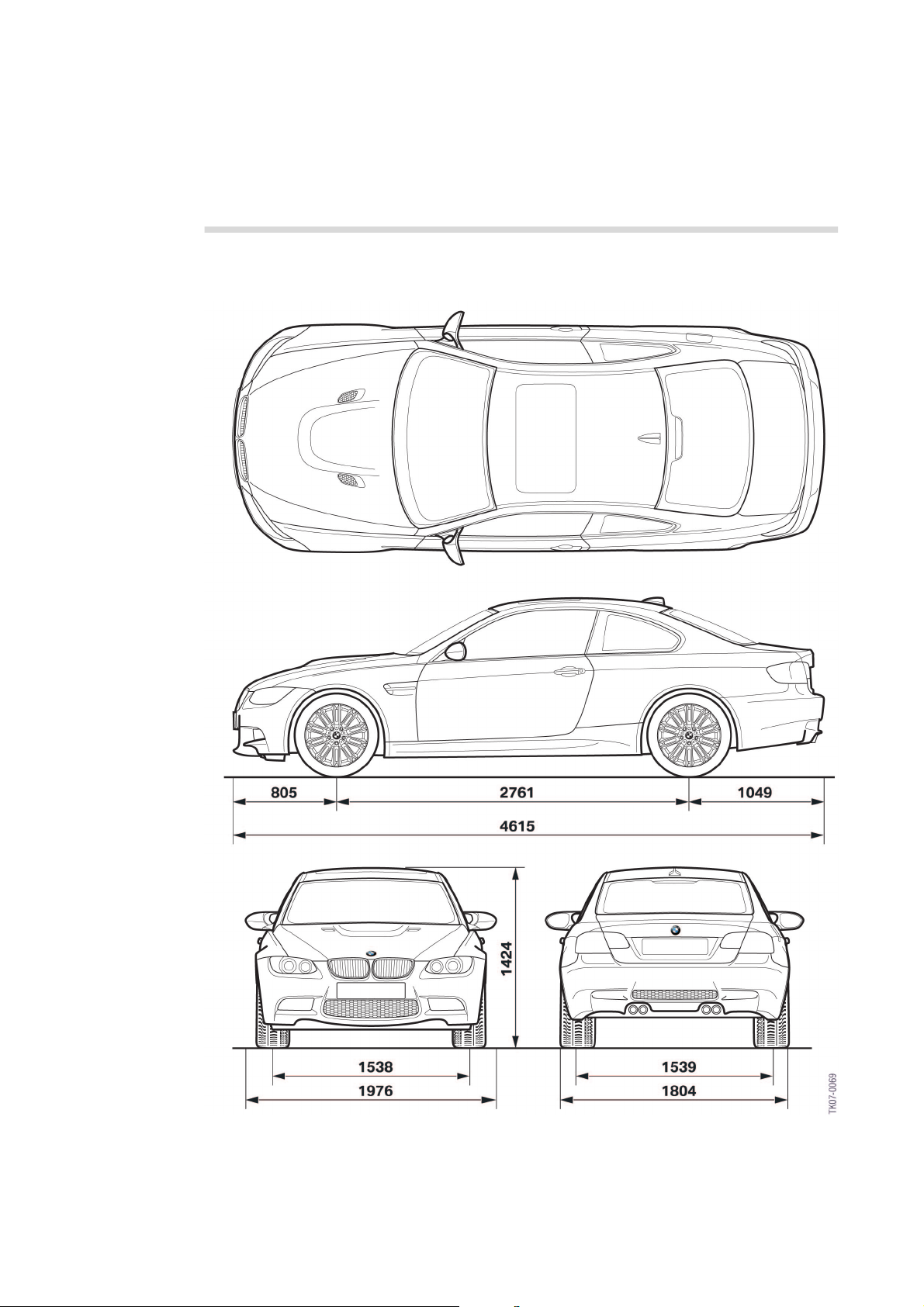
Dimensions and Vehicle Data
Garage dimensions
10 - Dimensions of the E92 M3
8
www.Bimmerfest.com
Page 15

Vehicle data comparison
6
Designation/Unit of
Measurement
Seats 4 5 4
Length [mm] 4615 4492 4580
Body width [mm] 1804 1780 1782
Width above mirror [mm] 1976 1924 1985
Height [mm] 1424 1383 1375
EU unladen weight [kg] 1655 1570 1600
Load volume [litres] 430 410 430
CwxA 0.68 0.66 0.62
Wheelbase [mm] 2761 2731 2760
Track width, front [mm] 1538 1508 1500
Track width, rear [mm] 1539 1525 1507
Steering
Average overall ratio
Manual transmission
gear ratio
Gear 1/2/3/4/5/6/R
Rear-axle finaldrive gearratio
[:1] fully
variable M limited slip
differential
E92 M3 E46 M3 Coupé E92 335i
Rack
12.5
GS6-53BZ (M)
4.055/2.396/1.582/1.192/
1/0.872/3.678
3.85
Yes
Rack
15.4
S6S420G
4.227/2.528/1.669/1.226/
1/0.828/3.746
3.62
Yes
Rack
16.0
GS6-53BZ
4.055/2.396/1.582/1.192/
1/0.872/3.678
3.08
No
Tyre type/Wheel rim type/
Front rim offset [mm]
Tyre type/Wheel rim type/
Rear rim offset [mm]
Brake disc front/rear
Diameter x thickness [mm]
Type of fuel [RON] 98 (min. 95) 98 (min. 95) 98 (min. 91)
Tank capacity/Reserve [litres] 63/8 63/8 63/8
EU consumption/distance
total [litres/km] 12.4/510 11.9/530 9.5/665
EU-CO2 emission [g/km] 295 287 228
Permitted emission limits Europe: EU4/E-OBD-EU4;
245-40 ZR 18/8.5Jx18/
IS29
265-40 ZR 18/9.5Jx18 /
IS23
(M Compound)
360x30/350x24
USA: US-LEV/US-OBDLEV 2, EVAP-LEV 2;
Japan: Japan LEV 200/
Japan OBD (same as EOBD)
225-45 ZR 18/8Jx18/
IS47
255-40 ZR 18/9Jx18 /
IS26
(M Compound)
325x28/328x20
EU3 EU4 (as for E92 M3)
225-45 WR 17 RSC/8Jx17/
IS34
255-40 WR 17 RSC/8.5Jx17/
IS37
(Compound)
348x30/336x22
www.Bimmerfest.com
9
Page 16
6
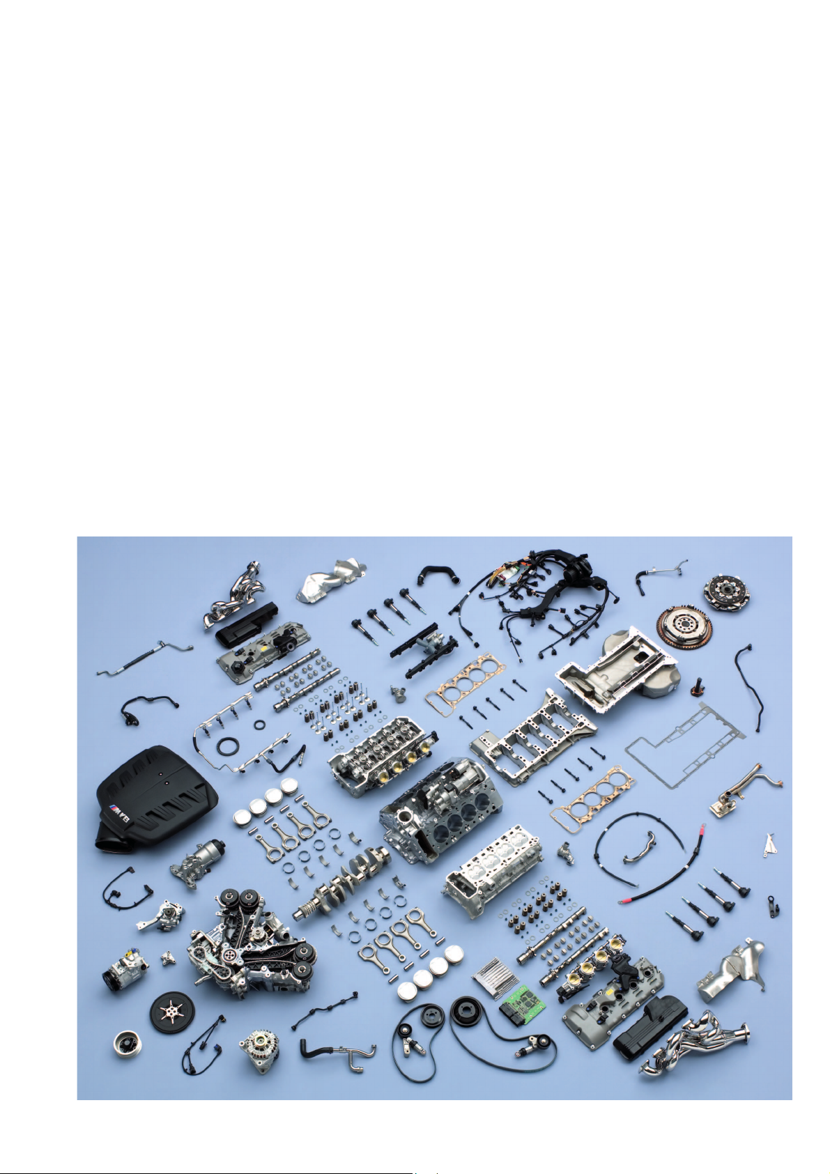
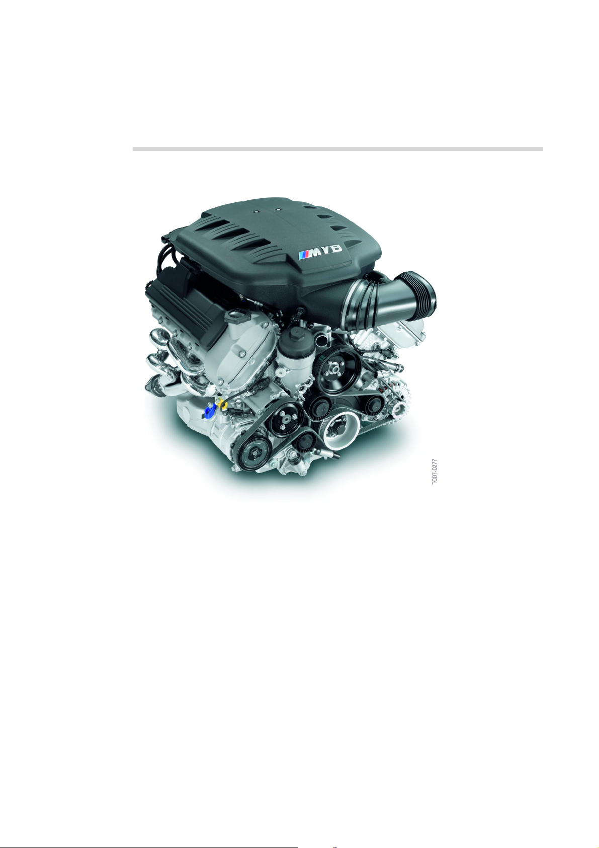
Engine and technical data
V8 with high engine speed concept
It will be the first time that a V8 engine has
been fitted in a series production M3. The
main concept behind this high-revving, high
performance enginewith a sportysound is the
extremely light, rigid and robust construction
which is capable of reaching extreme engine
speeds of up to 8,400 rpm. The engine
achieves an impressive 420 hp (over 100 hp
per litre).
The S65B40 is derived from its big brother,
the S85B50. The main changes can be seen
11 - S65B40 front view
in the engine oil system, VANOS valve gear
system and air intake system. Special
consideration has also been given to engine
weight optimization.
The engine with all its assemblies is built inthe
special engine production area of the Munich
BMW plant.
One standard engine is used throughout the
world and adapted to suit specific market
requirements.
10
www.Bimmerfest.com
Page 17
6
A new dimension to the high engine
speed concept
The M engineers consider the high engine
speed concept to be the most intelligent
strategy of obtainingthe maximum thrustfrom
a vehicle.
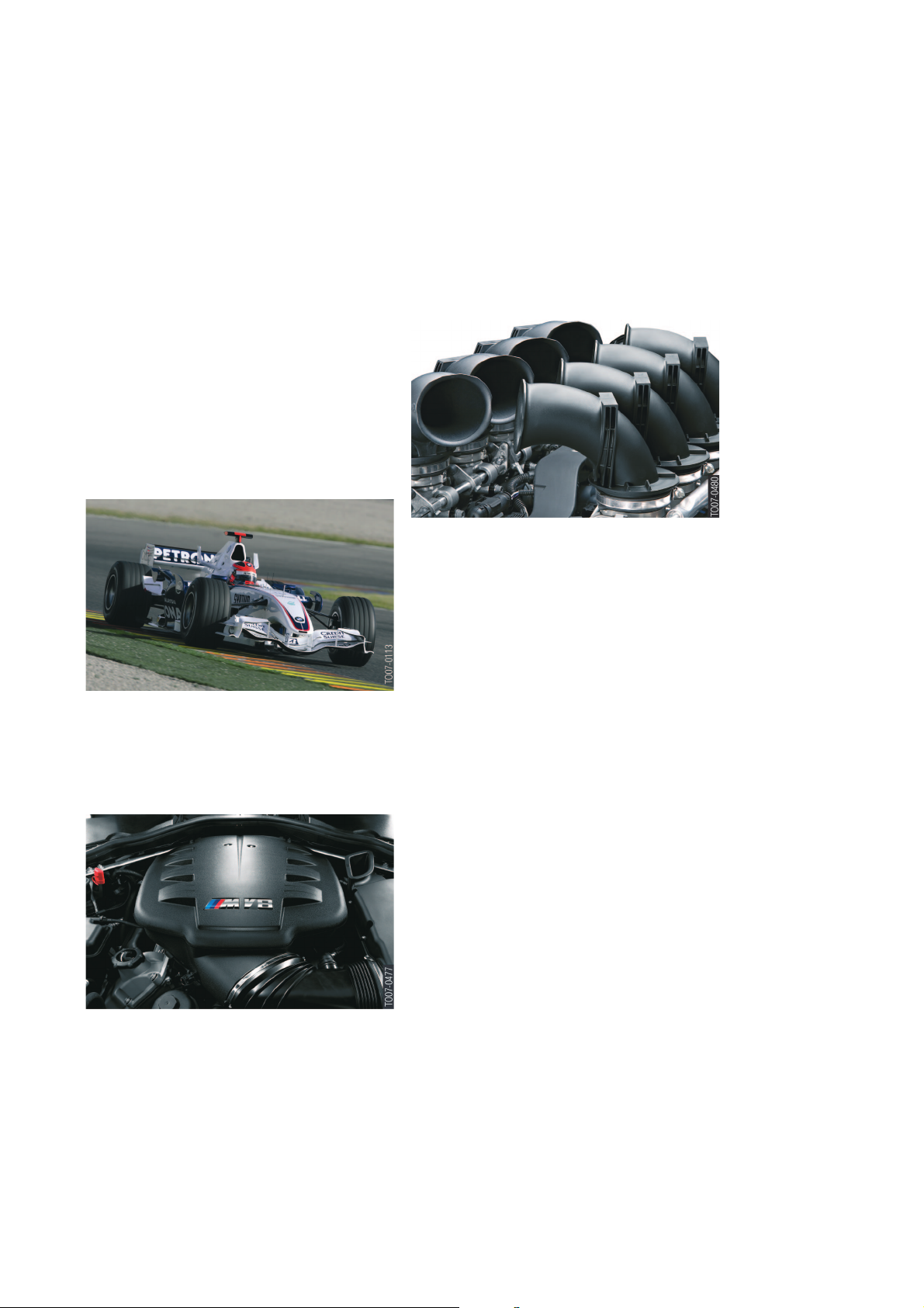
For example, in a modern formula 1 engine,
the crankshaft works at up to 19,000 rpm
(resulting in piston speeds of over 25 metres
per second).
The actual thrust at the driven wheels is the
decisive factor for car acceleration. This thrust
is achieved by the engine speed, the torque
and the short gear ratio.
12 - Formula 1 example
This concept has beenadopted forvehicles in
the 'M' range from motor sport. The fully
variable M limited-slip differential means that
the thrust is optimally distributed to the live
axle.
Furthermore, the S65B40 also includes the
established M-specific features such as
double VANOS, individual throttle butterflies
and high-performance engine electronics
(MSS60 control unit).
14 - S65B40 Notional view without the intake manifold
Technical workarounds by increasing the
cylinder capacity or boosting become
superfluous, thus avoiding the increased
engine weight and consumption often
associated with these methods.
The high engine speed concept helps to
achieve dynamically agile handling and the
maximum in sports driving performance
characteristics.
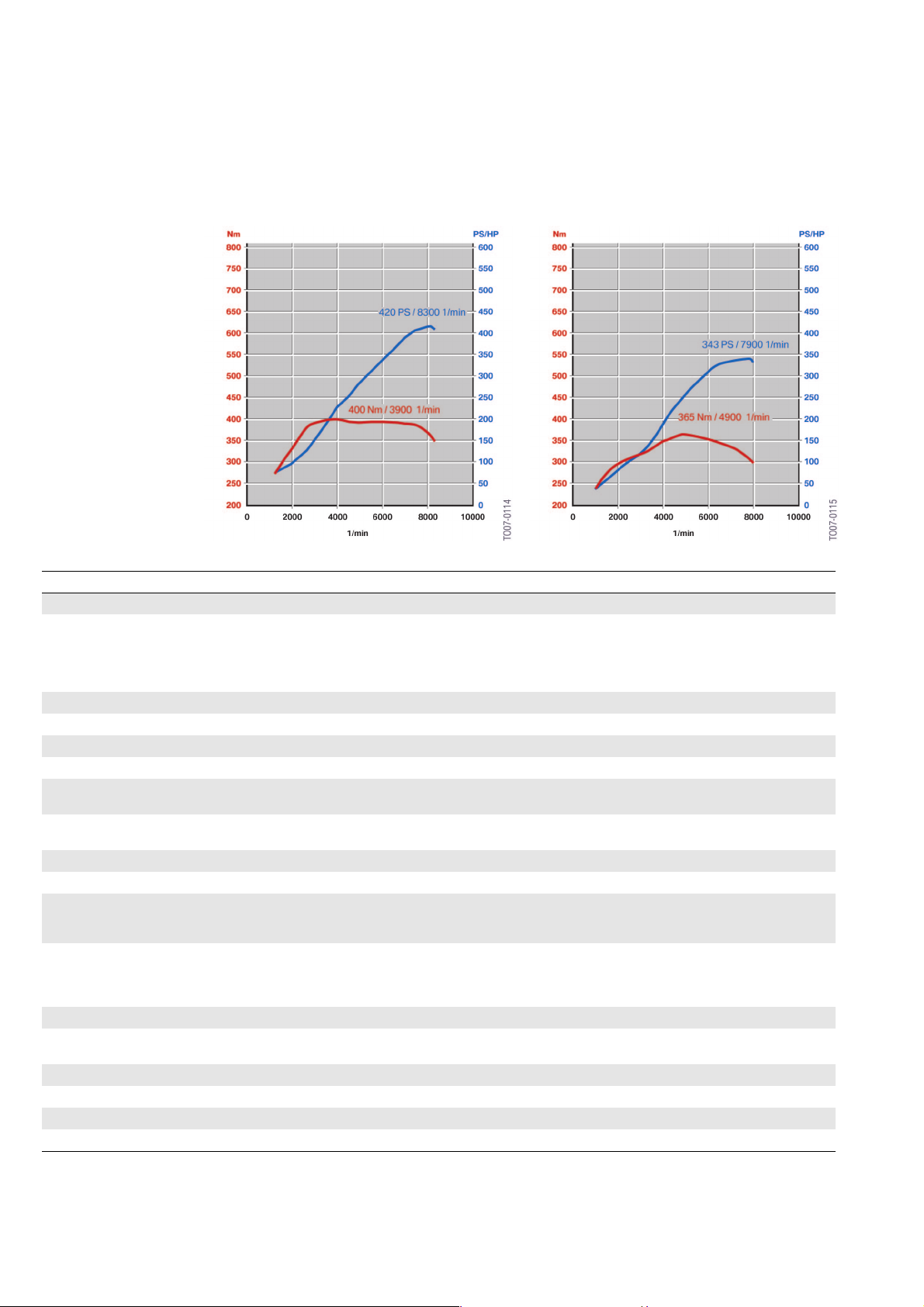
A maximum torque of 400 Newton meters at
3,900 rpm is reached. Approx. 85 percent
(340 Nm) can be utilized beyond the
enormous engine speed range of 6,500 rpm.
The S65B40 attains 8,400 rpm, and therefore
a value that was previously only reserved for
racing car engines or exotic custom vehicles.
3 For safety reasons, due to the engine
dynamics when the vehicle is stationary (i.e.
without a road-speed signal), it is already
down-controlled at 7,000 rpm to prevent the
engine speed from increasing into an
impermissible range. 1
13 - S65B40 View of the intake manifold
11
www.Bimmerfest.com
Page 18
6
15 - E92 M3: S65B40O0 Power and Torque Curve 16 - E46 M3: S54B32O0 Power and Torque Curve
Technical Data E92 M3 E46 M3 E6x M5/M6
Engine identifier S65B40O0 S54B32O0 S85B50O0
Engine type
firing order
firing interval [° KW]
Cylinder capacity [cm3] 3999 3246 4999
Bore [mm] 92 87 92
Stroke [mm] 75.2 91 75.2
Space between cylinders [mm] 98 91 98
Power [hp/kW]
at speed [rpm]
Torque [Nm]
at speed [rpm]
Breakaway speed [rpm] 8400 8000 8250
Compression ratio 12:1 11.5:1 12:1
Engine control
Combustion monitoring
Fuel delivery
Fuel delivery pressure [bar]
Camshaft drive 2x double-roller chain Double-roller chain 2x single-roller chain
Variable camshaft control
(VANOS)
Adjustment range E/A [°KW] 72-130/81-129 70-130/83-128 79-145/91-128
Kingpin inclination E/A [°KW] 58/48 60/45 66/37
Response time E/A [°KW] 256/256 260/260 268/260
Engine weight [kg] 202 217 240
V8 engine with 90° engine block and 17
mm cylinder bank offset
4 valves per cylinder.
1-5-4-8-7-2-6-3
90
420/309
8300
400
3900
MSS60
Ion current monitoring
DME => Electric fuel pump control (LolCAN) => three-phase flow pump
3-6
2x double (engine oil pressure)
oscillating rotor VANOS
6 in-line engine/
4 valves per cylinder
1-5-3-6-2-4
120
343/252
7900
365
4900
MSS54
Standard misfiring and
knock identification
DME
=> DC pump
5
Double
high-pressure VANOS
V10 engine (design as S65)
1-6-5-10-2-7-3-8-4-9
90/54
507/373
7750
520
6100
MSS65
Ion current monitoring
DME => Electric fuel pump
control (PWM) => Double
pump system
3-6
2x double
high-pressure VANOS
12
www.Bimmerfest.com
Page 19
6
Overview of Special Features
Body:
• M3 Front and rear apron
• Carbon fibre roof in matching colour, if no
optional sliding/tilt sunroof
• Gills in front side panels
• M3 outside mirrors
• Aluminium hood with "Power Dome" and
air inlet
• M dome braces, thrust panel and
underbody V-brace
• Weight-optimized bumper brackets, front
and rear
• Optimized heat isolation package
• Optimized noise isolation package
• Optimized underbody panelling, front and
rear.
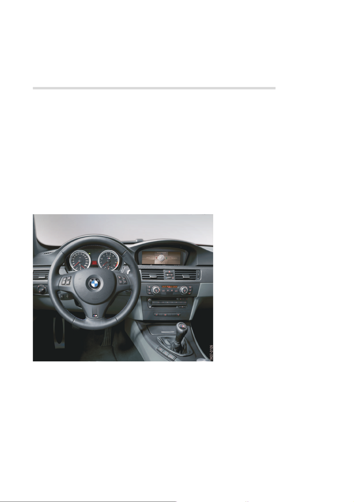
Interior:
• M3 steering wheel
• M gear lever
• M driver foot supports
• M3 seats
• Lighter floor trim (carpet)
• Lightweight design through-loading in rear
Electrics:
• M3 Instrument cluster
• M-specific switches for gear lever in the
centre console
• Buttons for the tyre pressure system
between centre air conditioning outlets
• Intelligent generator control (IGR)
• AGM battery.
www.Bimmerfest.com
17 - E92 M3 cockpit
Engine:
• New high-engine-speed concept V8
engine S65B40 with MSS60 engine
control system
• M3 Air intake guide
• M Individual throttle butterflies
• M Ion-flow combustion monitoring
• M VANOS
• M3 Exhaust system
13
Page 20

6
Drive:
• Dual-disc clutch used in an M3 for the first
time
• M 6-gear manual transmission
• Fully variable M differential with locking
action
Chassis:
• M3 Rims, tyres
• M3 Compound brake system
• Adapted front axle carrier, M front axle
components
• Servotronic hydraulic steering, M steeringgear ratio
• Adapted rear axle carrier,
M rear axle components
M-specific options:
• MDrive menu
• EDC-K
• 19" M3 rims, tyres
• Seat back width adjustment (passive)
• Enhanced leather interior
• High speed down-control option 7ME "M
Driver’s Package" (280 km/h).
Individualization options:
• BMW Individual High End audio system
• Individual highly-polished shadow line
• Individual interior trim
• Individual paint finishes.
14
www.Bimmerfest.com
Page 21

Competitor comparison
6
Designation/Unit of
Measurement
Engine configuration/no.
of cylinders/Valves per
cylinder
Cylinder capacity [cm3] 3999 3596 4163 6208
Bore/Stroke [mm] 92/75.2 96.0/82.8 84.5/92.8 102.2/94.6
Power [hp/kW]
at speed [rpm]
Torque [Nm]
at speed [rpm]
Compression ratio, Type
of fuel [RON]
Power [hp] per litre 105.0 90.4 100.9 77.5
EU unladen weight [kg] 1655 1470 1725 1755
EU power to weight ratio
[kg per PS] 3.94 4.52 4.11 3.65
Acceleration
0-100 km/h [s]
V
[km/h] *
max
electronically limited
Drive type Rear axle Rear axle All-wheel Rear axle
Transmission 6-gear 6-gear 6-gear 7-gear automatic
Type of tyres, front/rear 245/265-40 ZR 18 235/265-40 ZR 18 4x255-40 ZR 18 255-40/35 R18
EU consumption, total
[litres/km] 12.4 11.0 13.4 14.2
Tank capacity [litres] 63 64 63 62
EU-CO
emission [g/km] 295 266 322 338
Permitted emissions
limits
Length/width/height
[mm]
CwxA 0.68 0.56 0.67 NA
Wheelbase/turning circle
[mm/m] 2761/11.7 2350/10.9 2648/11.3 2715/10.76
Track width front/rear
[mm]
EU payload [kg] 500 340 482 420
Load volume [litres]
2
E92 M3 Porsche 911
Carrera
V8 / 4 Boxter 6/4 V8 / 4 V8 / 4
420/309
8300
400
3900
12.0:1
98
4.8 5.0 4.8 4.7
250*
(280)
EU 4 EU 4 EU 4 EU 4
4615/1804/1418 4427/1808/1310 4586/1816/1415 4652/1740/1413
1538/1539 1486/1534 1559/1569 1493/1474
430 135 460 435
325/239
6800
370
4250
11.3:1
98
285 250* 250*
Audi RS4 MB CLK 63
AMG
420/309
7800
430
5500
12.5:1
98
481/354
6800
630
5000
11.3:1
98
www.Bimmerfest.com
15
Page 22

6
16
www.Bimmerfest.com
Page 23

7
System overview.
E92 M3 Complete vehicle.
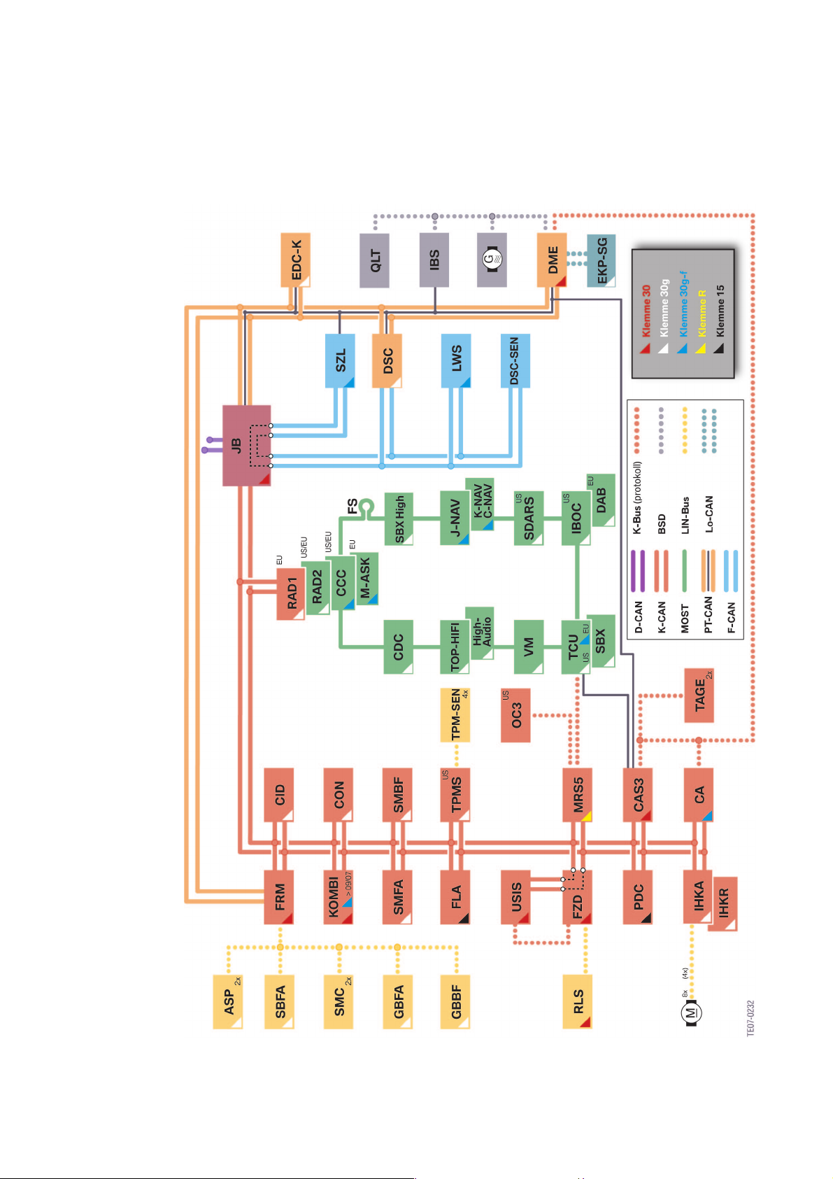
Vehicle electrical system/terminal status
The vehicle electrical system is based on the
E92 series production vehicle system and has
been adapted for the M3.
www.Bimmerfest.com
17
Page 24
7
18
1 - E92 M3 vehicle electrical system overview and terminal status
www.Bimmerfest.com
Page 25

7
Index Explanation Index Explanation
ASP Outside mirrors IHKR Integrated heating/air conditioning
system
CA Comfort Access JB Junction box
CAS Car Access System KOMBI Instrument cluster
CCC Car Communication Computer LWS Steering angle sensor
CDC (Compact) CD changer M-ASK Multi-audio system controller
CID Central information display MRS5 Multiple restraint system, 5th
generation
CON Controller OC3 Seat occupancy detector mat (US)
DAB Digital Audio Broadcast PDC Park distance control
DME Digital motor electronics QLT Quality, level, temperature oil
sensor
DSC Dynamic Stability Control RAD Radio1 or Radio2
DSC-SEN DSC sensor RLS Rain light sensor
DWA Anti-theft alarm system SBFA Switch block, driver's door
EDC-K Continuous Electronic Damping
Control
EKP Electric fuel pump control unit SBX High Interface box High
FLA High beam assistant SDARS Satellite tuner (US only)
FRM Footwell module SMBF Passenger's seat module
FS MOST direct access SMC Stepper motor controller
FZD Roof function centre SMFA Driver's seat module
GBBF Seat beltextendercontroller,front
passenger
GBFA Seat belt extender controller,
driver
HighAudio
IBOC In Band On Channel (Digital
IBS Intelligent battery sensor USIS Ultrasonic passenger-
IHKA Integrated automatic heating/air
BMW Individual High End
Audiosystem
Radio)
conditioning system
SBX Interface box (ULF functionality)
(Bluetooth telephony, voice input
and USB/audio interface)
SZL Steering column switch cluster
TAGE Outside door handle electronics
TCU Telematics Control Unit
TOP-HiFi Top-HiFi amplifier
compartment sensor
VM Videomodule (only for US)
www.Bimmerfest.com
19
Page 26
7
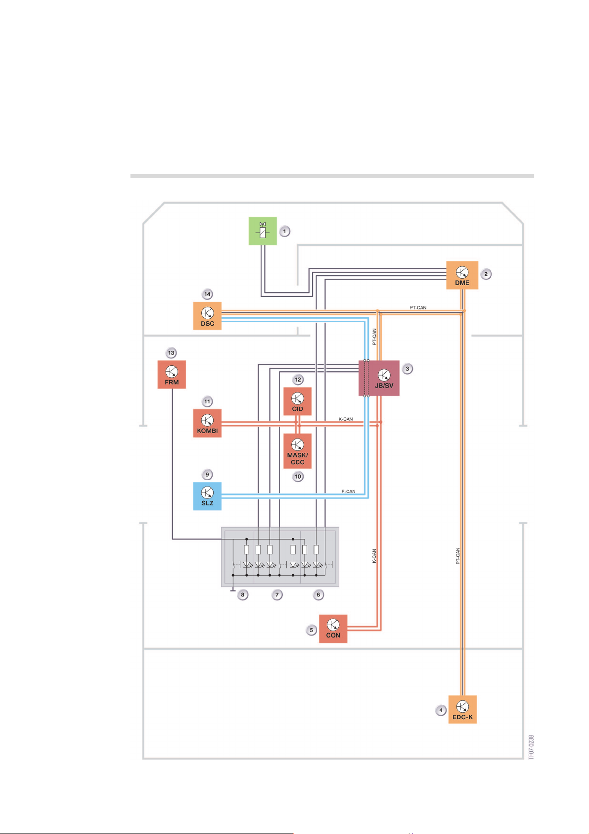
MDrive
MDrive system circuit diagram
20
2 - E92 M3 MDrive system circuit diagram
www.Bimmerfest.com
Page 27

7
Index Explanation Index
1 Servotronic valve 8 DSC button
2 DME MSS60 9 Steering column switch cluster
3 Junction box distribution box 10 Multi audiosystemcontroller/Car
Communication Computer
4 Electronic Damping Control
controller
5 iDrive controller 12 Instrument cluster
6 POWER button 13 Footwell module
7 EDC button 14 Dynamic Stability Control
11 Central information display
The MDrive option
The MDrive menu known from the M5/M6 is
now also available as an option (SA 2MD) in
the M3.
Starting from the iDrive main menu, the
MDrive menu can be called up by pressing on
the iDrive controller and selecting M settings.
The iDrive controller can be used to configure
the different MDrive settings ready to be
called up.
The overall setting is called up/activated by
pressing on the M button on the steering
wheel. Pressing the M button again or
restarting the vehicle deactivates the settings.
The settingscan, of course, be retrievedagain
using the M button.
The following is a list of menu items with
selection options that are currently
available in the MDrive menu:
• M Engine Dynamics Control (Power)
– "Unchanged"
– "Normal"
– "Sport"
– "Sport Plus"
• DSC
– "Unchanged"
– "OFF"
– "ON"
– "M Dynamic mode"
• Servotronic
– "Normal"
– "Sport"
• EDC-K (only if fitted)
– "Unchanged"
– "Comfort"
– "Normal"
– "Sport".
By selecting "Unchanged", whentheMbutton
is pressed (i.e. the settings in the MDrive
menu are called up), the current settings of
this system are retained.
Example:
The driver has deactivated the Dynamic
Stability Control function using the DSC
button.
MDrive setting: M Engine dynamics control
"Sport Plus"; DSC "Unchanged"; Servotronic
"Sport".
The driver presses the M button on the
steering wheel to call up the M settings.
Only the "Sport Plus" and Servotronic "Sport"
settings for M engine dynamics control are
activated.
DSC remains deactivated.
www.Bimmerfest.com
21
Page 28
7
Information on the menu items
M Engine Dynamics Control (Power)
Apart from"Unchanged", three enginecontrol
programs are available;
"Normal", "Sport" and "Sport Plus".
The options determine how spontaneously
the engine responds to actuation of the
accelerator pedal.
The maximum engine power is not changed.
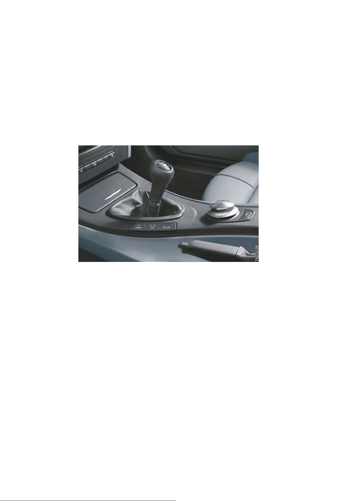
Using the power button in the centre console,
the driver can only choose between "Normal"
and "Sport".
"Sport Plus" is only available in the MDrive
menu.
3 - E92 M3 centre console
with iDrive controller
DSC
Apart from the "Unchanged" setting, in the
DSC submenu, the options "OFF" "ON" and
"M Dynamic mode" can be selected.
If "M DynamicMode" is selected, theDynamic
Stability Control (DSC) permits higher slip
values at the wheels.
The system does not activate the stabilizing
function until very close to the handling limit
range, when itinfluences engine outputand/or
actively engages the brakes.
In "OFF" mode, an experienced sports car
driver can also completelydeactivate the DCS
function.
Using the DSC button in the centre console,
the driver can switch between "OFF" and
"ON" or if "M Dynamic Mode" is active,
between "M Dynamic Mode" and "OFF".
"M Dynamic Mode" is only available in the
MDrive menu.
EDC-K
If option 223 continuous Electronic Damper
Control is fitted together with MDrive, in
addition to "Unchanged", three EDC
programs can be selected in the MDrive
menu: "Comfort", "Normal" and "Sport".
The driver can use the EDC button in the
centre console toswitchsequentially between
the three programs.
22
www.Bimmerfest.com
Page 29

7
Servotronic
The settings that can be selected for the
Servotronic steering function are "Normal"
and "Sport". Depending on the selection, the
appropriate characteristic curve for powerassisted steering is active.
This selection option is only available in the
MDrive menu. Without MDrive, the customer
has nooption, and a fixed programmedspeeddependent characteristic curve is used.
"Key-dependent settings" menu
Under "M settings", the "Key-dependent
settings" menu is also available as well as the
MDrive menu.
This allows key-specific settings for certain
MDrive menu items.
M engine dynamics control and EDC settings
are currently possible, which are assigned to
the specific key used during the configuration
(configuration => ZV closing action =>
memorizing).
Under the M engine dynamics control menu
item, "Normal" or "Sport" can be selected.
In the EDC menu item, the options "Comfort",
"Normal" or "Sport" can be selected.
www.Bimmerfest.com
23
Page 30

7
24
www.Bimmerfest.com
Page 31

8
System components.
E92 M3 Complete vehicle.
Body/Interior trim and equipment:
Bodyshell
Due to changes to the wheel arch and the
carbon roof, the bodyshell components shown
in blue
have a different part number to the seriesmodel E92.
1 - E92 M3 bodyshell components, view from above
2 - E92 M3 bodyshell components, view from below
www.Bimmerfest.com
25
Page 32

8
New body side panels which are 20mm wider
each sideover the flaredrear wheel archesare
typical of the ’M’ design.
To ensure the necessary M3 wheel clearance
at the rear wheel arch, the side frame wheel
arch has been extended by approximately 20
mm, and the 180° joining lip edge inside the
wheel arch has been rolled upwards to further
increase the wheel clearance in the wheel
housing.
3 - E92 M3 Rear weel arc
26
www.Bimmerfest.com
Page 33

Additional reinforcements
8
4 - E92 M3 Overview of additional bolted-on reinforcements
The E92 M3 is equipped with a v-shaped
reinforcement brace in the engine
compartment, known as thedomestrut, which
consists of five separate components. It is
secured to the suspension strut dome and
screwed centrally to the middle of the
bulkhead.
5 - E92 M3 Dome strut
www.Bimmerfest.com
27
Page 34

8
The E92M3, just likethe E46 M3,is equipped
with a reinforcement plate, known as the
thrust panel, made from aluminium alloy.
The thrust panel primarily increases the
torsional strength while also acting as a lower
The V-shaped braces used in the rear
underbody area of the series production E92
have been strengthened and adapted, and in
the M3are permanently welded to the tension
strut and screwed to the body with the
transmission tunnel bridge (in the series E92
motor cover and oil pan protection. The thrust
panel is fitted to the axle carrier with six bolts
from below, and has two openings for
changing the oil.
6 - E92 M3 thrust panel
they are screwed to the tension strut and
welded to the bridge).
The bridge has been strengthened and
adapted. In theM3, it isalso used to mountthe
exhaust line.
28
www.Bimmerfest.com
7 - E92 M3 Rear axle braces
and transmission tunnel
bridge
Page 35

Exterior Body
8
8 - E92 M3 View of M3-specific external body components
9 - E92 M3 View of M3-specific external body components
www.Bimmerfest.com
29
Page 36

8
The doors and the tailgate are taken from the
series-model E92. All other external body
components are new.
• New "Powerdome" aluminium hood lid with
air apertures. The aperture on the left when
viewed in the direction of travel is used for
incoming engine air, and the right-hand
aperture offers optical symmetry.
10 - E92 M3 Power Dome
aluminium hood lid
30
www.Bimmerfest.com
Page 37

8
• The roof on the E92 M3 is manufactured
from carbon fibre. This has reduced the
overall vehicle mass on the upper level of
the car by approximately 5 kg, therefore
considerably lowering the centre of gravity.
Unlike the E46 M3 CSL, a roof rack system
can be assembled on the E92 M3 with
carbon fibre roof. The carbon fibre roof of
the E92 M3 has specific inserts for roof
luggage rack brackets.
The repair procedures and
options are similarto or the sameas the M6
(see the service literature for more
information).
If the sunroof option is selected, a steel roof
similar to the series model E92 is fitted.
• An advanced plastic material is used for the
front side panels, which are wider than
those used on the series E92. The side
panels include the model-specific "M side
gills" withintegrated side indicatorsand M3
emblem.
• The side sills are more highly accentuated,
in accordance with the M design criteria.
11 - E92 M3 Carbon roof
12 - E92 M3 Front side panel
13 - E92 M3 Side sill trim
www.Bimmerfest.com
31
Page 38

8
• The ’M’ designedexterior door mirrors have
an optimized air flow design. The mirror
surface area is larger to comply with future
legislation. The mirror base mounting has
been adapted to suit the new mirror unit.
The functions of the outside mirrors are the
same as the series production E92. Driver
and passenger mirrors are electrically
heated and adjusted.
14 - E92 M3 Outside mirrors
on the vehicle
• The cover capof the exteriormirror housing
is painted in the body colour.
15 - E92 M3 Outside mirror (view from the mirror side)
Outside mirrors with memory and folding
functions and/or automatic anti-glare
control are optionally available.
16 - E92 M3 Outside mirror (view from the trim side)
32
www.Bimmerfest.com
Page 39

8
• The tailgate is taken from the series
production E92. Therear spoiler (Gurney)is
attached as a standard feature on the E92
M3. It can optionally be removed.
With the option 7ME "M Driver’s Package"
(high speed limiting), the spoiler is
permanently fixed.
The new M3isfitted with larger wheelhousing
covers that accommodate the larger wheels
and flared wheel arches. The front wheel
housing cover has been adapted specifically
to meet the M3 requirements.
Front wheel housing cover
18 - E92 M3 Front wheel housing cover
17 - E92 M3 Tailgate and
Rear wheel housing cover
19 - E92 M3 Rear wheel housing cover
spoiler (Gurney)
www.Bimmerfest.com
33
Page 40

8
Front End Module
The front end module has a new single piece
M-specific thermoplastic bumper trim and is
fitted to a reinforced lightweight plastic
bracket.
20 - E92 M3 Front end module
Index Explanation Index Explanation
1 Bumper trim 3 Bumper bracket
2 Shock absorber foam
21 - E92 M3 Bumper brackets
34
www.Bimmerfest.com
Page 41

8
22 - E92 M3 Front bumper
trim
The bumper trim is colour coded to the car.
The front M3 bumper has apertures for the
kidney grill, engine air inlet, PDC ultrasonic
sensors (optional), the headlight-cleaning
Headlight cleaning system (SWR)
system and the mounting for the towing eye.
Front bi-xenon headlamp units are identical to
the series E92. The M3 front bumper
overhang is longer than that of the series E92.
The container for the M3 headlight cleaning
system is new. The design has been changed
from the series E92 in order to provide the
necessary spacefor installing the M3 sidegills
with integrated indicators in the M style. The
filler neck and the line for the headlight
cleaning system are new, together with the
fixed washer nozzles on the bumper trim.
www.Bimmerfest.com
23 - E92 M3 Headlight
cleaning system
The wiring harness section for the headlight
cleaning system has been adapted
accordingly.
35
Page 42

8
Rear End Module
24 - E92 M3 Rear end module
Index Explanation Index Explanation
1 Bumper trim 3 Bumper bracket
2 Shock absorber foam
The rear end module also features a new,
single-piece bumper trim in the M style made
from a special thermoplast material. The
bracket is also made from reinforced
lightweight plastic.
The module has apertures for the bumper
grid, PDC ultrasonicsensors (optional) andthe
mounting for the towing eye.
25 - E92 M3 Rear bumper trim
36
www.Bimmerfest.com
Page 43

Sound insulating mat and thermal
insulation
8
New sound insulation and thermal insulation
covers have been installed.
The sound-insulatingmats areattached in the
vehicle interior to the bulkhead and
26 - E92 M3 Sound insulating
mat and thermal insulation
transmission tunnel, and the thermalinsulation
is mounted in the underbody area of the
exhaust system and the engine.
www.Bimmerfest.com
37
Page 44

8
Other underbody panelling
27 - E92 M3 Underbody panelling
The underbody panels have been optimized
to ensure the best possible vehicle
aerodynamics and the maximum possible
cooling capacity for the driveline components.
38
www.Bimmerfest.com
Page 45

Interior Body
8
The M3 floor insert in the luggage
compartment has been modified to
accommodate the M Mobility System.
28 - E92 M3 Implementation of the M Mobility System
29 - E92 M3 Seat structure
Index Explanation Index Explanation
1 Seat upholstery 3 Seat width adjustment
2 Backrest
Two M3 seat versions are available: The
’Speed’ version is a cloth/leather combination
that is included in the standard equipment,
and the ’Novillo’ is a full leather seat option.
The "Novillo" type is also available in an
extended version. In the extended version, the
bottom of the dashboard and the side walls of
the centre console are also covered with
leather in a matching colour.
The versions also differ in their covers and
stitching.
The frame and the foam structure are
identical.
The front head restraints feature the M logo,
as in the E6x M5.
In order to provide an enhanced sporting
character and more hold, the seat cushions
and backrests inEuropean vehicles havebeen
further developed. In US vehicles, only the
front seat backrests have been revised. The
seat upholstery installed in US vehicles is the
same as that used on the E92 series-model
sport seat.
www.Bimmerfest.com
39
Page 46

8
The optional backrest width adjustment is a
further development of the series E93 sport
seat andis available as an optiontogether with
a lumbar support. In the M3, this is manually
operated (passively).
The rear backrest cover is always black.
The ’Speed’seat is currentlyonly available ina
combination of black leather and anthracite
fabric covering.
The leather ’Novillo’is currently available inthe
following finishes:
• Black leather
• Palladium silver leather
• Fox red leather
• Bamboo beige leather
New door trim/side trim panels are used.
The frame with rear seat bench with through-
loading capability has enabled further weight
savings in the E92 M3 (similar to the E46 M3
CSL). This is achieved through the use of
lighter materials, which are processed using a
special method for seat construction in a
sandwich design (1).
30 - E92 M3 "Novillo" seat in palladium silver
31 - E92 M3 Sectional view of the frame of a rear seat back (1)
32 - E92 M3 Rear seat bench
40
www.Bimmerfest.com
Page 47

8
S65B40O0 Engine
Engine block with bedplate construction
33 - S65B40 Engineblock with
bedplate construction
Index Explanation Index Explanation
1 Engine block (upper section) 3 Bedplate construction (lower
section)
2 Grey cast iron inlays
The construction and materials are identical to
the S85; the upper low-pressure die-cast
crankcase is made from an aluminium-silicon
alloy.
The cylinder bores are formed using exposed
hard silicon crystals, rendering the use of
cylinder liners redundant.
The lower crankcase (bedplate) is also
constructed using die-cast aluminium. Due to
the extreme forces, grey cast iron inlays are
used to reinforce the bedplate construction.
These also limit crankshaft bearing clearances
over a greater temperature range and thus
have a positive effect on the oil flow rate.
www.Bimmerfest.com
41
Page 48

8
Crankshaft
The five-bearing crankshaft is forged from a
single piece, including the two double-chain
wheels for driving the valve gear. The gear
wheel for the oil pump drive is flangemounted. The cylinder spacingis 98 mm. The
crankshaft possesses a high level of bend
resistance and high torsional strength at a
relatively low weight. The crank pin offset is
90°. The diameter of the main bearing journal
is 60 mm. The crankshaft end float is
controlled by a thrust bearing located at the
fifth main bearing.
For design reasons, the firing order
1-5-4-8-7-2-6-3 was chosen
for the S65, instead of the firing order
1-5-4-8-6-3-7-2 more commonly employed
in BMW V8 engines.
3 The identification marking of the bearing
shells is engravedonthe crankcase and onthe
first crank web. 1
42
Connecting rods
The weight-optimized, high tensile steel
connecting rods split by fracture separation
and the pistons are the same as those used in
the S85 engine. For weight reduction, the
upper section of the connecting rod has a
trapezium-shaped cross-section.
www.Bimmerfest.com
34 - S65B40 crankshaft with
magnification of theupper
section of the connecting
rod
3 The large connecting rod eye is
asymmetrically groundto reducethe length of
the engine. This means that the installation is
direction-specific.
For the workshop, bearing shells are available
in a repair stage (for more information, see the
service documentation). 1
Page 49

Pistons
8
Index Explanation
1 Pistons
2 Taper-faced ring
3 Gudgeon pin
4 Piston skirt
5 Oil scraper ring (VF system)
6 Compression ring (plain
compression ring with spherical
contact face)
35 - S65B40 Pistons
A piston is manufactured from a cast
aluminium alloy and weighs approximately
480 grams including gudgeon pin and piston
rings. The piston design is the same as the
S85 piston (piston shaft with galvanized iron
coating [Ferrostan] and a running-in layer
containing tin. The installation position is
direction-specific.
www.Bimmerfest.com
43
Page 50

8
Oil Supply
44
36 - S65B40 Hydraulic schematic of oil supply
www.Bimmerfest.com
Page 51

8
Index Explanation Index Explanation
1 Cylinder bank 1 VANOS exhaust
hydraulic motor
2 Cylinder bank 1 VANOS inlet
hydraulic motor
3 Cylinder bank 2 VANOS inlet
hydraulic motor
4 Cylinder bank 2 VANOS exhaust
hydraulic motor
5 Cylinder bank 1 VANOS exhaust
multiway adjustment valve
6 Cylinder bank 1 VANOS sieve filter
(max. 300 µm) before multiway
adjustment valve
7 Cylinder bank 1 VANOS inlet
multiway adjustment valve
8 Cylinder bank 2 VANOS inlet
multiway adjustment valve
9 Cylinder bank 2 VANOS sieve filter
(max. 300 µm) before multiway
adjustment valve
10 Cylinder bank 2 VANOS exhaust
multiway adjustment valve
11 Cylinder bank 1VANOS non-return
valve
12 Cylinder bank 2VANOS non-return
valve
13 Cylinder bank 1 chain tensioner 27 Sump
14 Cylinder bank 1 and 2 non-return
valve from chain lubrication
15 Cylinder bank 2 chain tensioner
16 Main oil channel (lubrication points
engine block and cylinder head)
17 Oil pressure switch
18 Oil filter bypass valve
19 Oil filter
20 Oil filter outlet aperture
21 Non-return valve
22 Pressure limiting valve
23 Piston cooling nozzles
24 Oil pressure regulation line
25 Volume flow-controlled hinged
valve main oil pump
26 Oil return pump
Two oil pumps areinstalled in the S65 engine;
the oil return pump, which is driven via a
gearwheel by a crankshaft, and the volume
flow-controlled mainoil pump, driven via chain
drive by the oil return pump.
www.Bimmerfest.com
In the S85, the VANOS high pressure pump is
installed instead of the S65 oil return pump,
and the S85 oil return pump is contained in a
housing together with the main oil pump
(tandem pump).
45
Page 52

8
37 - S65B40 Oil pumps
Index Explanation Index Explanation
1 Oil intake area ofthe oil return pump 3 Main oil pan
2 Front, smaller section of the oil pan 4 Oil intake area of the main oil pump
Since there is no space to install a tandem
pump in the S65, the oilreturn pump hasbeen
moved from the main oil pump housing and
installed instead of the VANOS high-pressure
pump. This allows the pump drive principle
(crankshaft => gearwheel => pump => chain
=> pump) to be maintained. As in the S85, the
volume flow-controlled main oil pump is a
hinged-valve oil pump with a feed capacity
adjusted to suit the VANOS low-pressure
system.
The duocentric design of the oil return pump
ensures that oil is always available at the inlet
pipe of themain oil pump inthe rear area ofthe
oil pan,
i.e. even when braking sharply from high
speeds.
The electrical oil return pumps installed in the
S85 for scavenging the cylinder heads are no
longer required, which results in a further
weight saving.
This is made possible by the lower number of
cylinders, modification of the oil return routes,
and the large capacity of the oil pan.
The oilpan has acapacity of 8.3 litres (S859.3
litres).
The oil supply is also guaranteed at extreme
longitudinal and lateral accelerations of up to
1.4 times the normalgravitationalacceleration.
The oil filter housing is installed on the engine.
46
www.Bimmerfest.com
Page 53

8
Cylinder Head
The cylinderhead is constructed from a single
piece of aluminium alloy.
To reduce the number of sealing faces, the
secondary air channel has been integrated
back into the cylinder head.
The design of the cylinder head is based on
the S85. Changeshavebeen made in thefront
engine compartment to the VANOS and the
timing chain.
The inlet and exhaust tracts have been further
airflow-optimized. The integrated idle air
channel has been discontinued and replaced
by an idle air bar for each cylinder bank.
As in the S85, the camshafts are
manufactured as a hollow-cast, one-piece
construction with integrated sensor gears.
The weight-optimized valves with a 5 mm
shaft diameter and the spherical bucket
tappets with hydraulic valve clearance
adjustment are also used.
38 - S65B40 Cylinder head
Index Explanation Index Explanation
1 Camshaft 5 Intake passage
2 Bucket tappet with hydraulic valve
clearance adjustment
3 Beehive-shaped valve springs 7 Connection flange of the
4 Cylinder head
6 Valve
integrated secondary air channel
www.Bimmerfest.com
47
Page 54

8
Index Explanation
1 Spherical contact surface
2 Box tappet
3 Guide lug
These bucket tappets with a cylindrical
camshaft contact surface and rotational lock
allow a high level of convexity. This results in
effective valve lift characteristics with the
smallest possible tappet diameter and hence
tappet mass (ideal for high engine speeds).
39 - E92 M3 Bucket tappet
Technical Data E92 M3 E46 M3 E6x M5/M6
Engine identifier S65B40 S54B32 S85B50
Valve operation Bucket tappet Drag arm Bucket tappet
Valve head ∅ E/A [mm]
Valve shaft ∅ [mm]
Valve lift [mm]
autom. compensation for play
35/30.5
5
11.35
Yes
35/30.5
6
12
No
35/30.5
5
11.7 E; 11.5 A
Yes
48
www.Bimmerfest.com
Page 55

8
Camshaft drive
As in theS85,the inlet camshafts are drivenby
chain drive and the exhaust camshafts are
driven by a gearwheel drive. This means that
the inlet and exhaust camshafts always have
an opposite direction of rotation. In contrast to
the S85, which works with two single-roller
chains between the crankshaft and the inlet
crankshafts, in the S65, two double-roller
chains are installed. This is because of the
higher chain drive load in the V8 S65.
40 - S65B40 Drive valve
control
Technical Data E92 M3 E46 M3 E6x M5/M6
Engine identifier S65B40 S54B32 S85B50
Camshaft drive 2x double-roller chain Double-roller chain 2x single-roller chain
The VANOS adjustment units are an integral
component of the valve control and are
mounted on therelevant camshaft bya central
bolt.
3 The central bolts of the inlet and exhaust
side have a CCW thread, please refer to the
repair instructions. 1
www.Bimmerfest.com
49
Page 56

8
VANOS
This has been made possible by the
considerably stronger switching moments at
the camshaft comparedtothe10-cylinder and
6-cylinder engine, particularly in the lower
engine speed range. The low-pressure
system uses these switching moments to
adjust the overall gear ratio.
The oil is directed to the sealed oil chambers
(3 and 4) of the VANOS adjustment unit.
When the chambers are pressurized with oil
pressure, onechamber allows the camshaft to
advance whilst the other chamber allows the
camshaft to retard.
50
41 - S65B40 VANOS hydraulic motor
Index Explanation
1 Optimized hydraulic rotor pressure
surfaces
2 Optimized inlet channel
oil chamber 1
3 Oil chamber 1
4 Oil chamber 2
5 Optimized inlet channel
oil chamber 2
The compact double VANOS system fitted to
the S65 engine operates at normal oil
pressure, unlike the S85 engine (which uses
high oil pressure). The low-pressure system
means that the high-pressure pump and
additional pressure lines and reservoir are
unnecessary. This results in a space saving as
well as a weight reduction of approx. 8.4 kg.
www.Bimmerfest.com
42 - S65B40 VANOS Hydraulic schematic of a cylinder bank
Index Explanation
1 Oil supply from the main oil
gallery
2 Non-return valves
3 Sieve filter upstream from
control valves
4 Hydraulic motor at the inlet and
exhaust camshaft
5 Multiway adjustment valves inlet
and exhaust side
6 Oil return flange to the oil sump
The VANOS oil pressure is supplied by the
engine’s mainoil pump. TheVANOS oil flowis
controlled by one multiway valve for each
camshaft. These VANOS multiway valves are
controlled by the MSS60 and are directly
installed in the cylinder head.
Page 57

43 - S65B40 VANOS hydraulic motor
Index Explanation
1 Locking pin spring
2 Locking pin
3 Spiral-wound spring
8
As with the S85, the VANOS adjustment unit
of the inlet camshaft drives the VANOS
adjustment unit of the exhaust camshaft by
means of a constantly meshed gear.
At zero pressure, a locking pin (2) also holds
the VANOS unit in the normal position or
engine start position.
The spiral-wound spring (3) is also used for
coordinating the adjustmenttimebetween the
advance and retard adjustment.
In contrast to AG petrol engines, the spiralwound spring for the inlet and exhaust sides is
mounted in the opposite working direction,
since the camshafts in the S65 rotate in the
opposite direction.
The principle of action of the hydraulic motor
in this M VANOS is based on the VANOS in
current BMW petrol engines and is optimized
for the S65 in terms of oil supply and drainage
diameters, and in the rotor surface area.
www.Bimmerfest.com
51
Page 58

8
44 - S65B40 Control diagram
Index Explanation
A [mm] Valve lift
B [°] Crankshaft angle
1 Exhaust camshaft
2 Inlet camshaft
The setting angle of the inlet camshaft is 58°
in relation to the crankshaft. The exhaust
camshaft has a setting angle of 48°.Asinthe
S85 engine, this VANOS also reaches an
adjustment rate of 360° camshaft per second.
Technical Data E92 M3 E46 M3 E6x M5/M6
Engine identifier S65B40 S54B32 S85B50
Variable camshaft
control (VANOS)
Adjustment range E/A
[°KW]
Kingpin inclination E/A
[°KW]
Response time E/A
[°KW]
2x double (engine oil
pressure) oscillating rotor
VANOS
72-130/81-129 70-130/83-128 79-145/91-128
58/48 60/45 66/37
256/256 260/260 268/260
3 The service instructions should be
followed exactly. TheVANOS adjustment unit
must not be disassembled. 1
Double
high-pressure
VANOS
2x double
high-pressure
VANOS
52
www.Bimmerfest.com
Page 59

8
Ancillary belt drive
The main belt drive drives the coolant pump
and the generator, while the auxiliary belt drive
drives the airconditioning compressor andthe
power-assisted steering pump.
The generator andthe coolant pump areinthe
same position as in the S85. The coolant
pump is identical to the S85, but has a larger
belt pulley.
45 - S65B40 Belt drive
www.Bimmerfest.com
53
Page 60

8
Air intake guide/Oil separator/Secondary air system
46 - S65B40 Air intake guide
Index Explanation Index Explanation
1 Engine hood air inlet 3 Air inlet in the bumper
2 Air inlet behind the ornamental
grilles of the BMW kidney
The combustion air enterstheenginevia three
flow-optimized air guides. Anairinletislocated
on the left side of the engine hood when
viewed in the direction of travel. To maintain
an optical balance in the appearance of the
engine hood, another intake grill is located on
the right-hand side, but this is blinded and
does not perform any function.
The second air inlet guide is located behind
the kidney grilles of the BMW kidney.
The third air inlet guide is on the left below the
front bumper.
The S65 has a large, single-piece air collector
for the intake air to both cylinder banks.
A cylindrical air filter element (4) with an
enlarged surface area is used.
The filtered air flows into the intake manifold,
from where it flows through eight integrated
4 Air filter element
individual inlet pipes and into the individual
throttle valve assemblies.
To optimize air resistance, no air-mass sensor
is installed in the intake area.
The air flow is determined using a modelbased calculation from the aperture of the
throttle valve assemblies and the idle speed
actuator, the VANOS adjustment position, the
engine speed, the air temperature and the
atmospheric pressure.
For safety reasons, an additional pressure
sensor is mounted in the idle speed system
(see idle speed control).
54
www.Bimmerfest.com
Page 61

8
Oil separators
47 - S65B40 Oil separator connection point to the intake manifold
The oil separators are bolted onto the cylinder
head covers. The connection between the oil
separator and the intake manifold is not
screwed but plugged. This reduces the risk of
incorrect assembly.
As is typical for the M series, no crankcase
pressure control is mounted/integrated.
Secondary air system
The secondary air pump is mounted on the
rear side oftheengine in the "V"ofthe cylinder
banks. The secondary air is guided into the
relevant exhaustchannel via a check valveand
an air channel integrated in the cylinder head.
An upstream secondary air pump hot-film airmass sensormeasures the secondary air flow.
The structure and function are the same as
the system inthe E60 M5andare described in
the PI E60 M5.
www.Bimmerfest.com
55
Page 62

8
Individual throttle butterfly system
56
Index Explanation Index Explanation
1 Double throttle valve sensor
cylinder bank 1 and 2
2 Individual throttle valve assemblies
The design principle of the S65 individual
throttle valve air intake system is the same as
the S85 and consists of eight individual
throttle valve assemblies and two electrical
throttle valve actuators. One electric throttle
valve positioner activates four individual
throttle butterflies of one cylinder bank, which
are mechanically coupled. The throttle valve
position for each cylinder bank is recorded
using a double throttle valve sensor on the
shared throttle body shaft. A signal is sent
directly to the throttle valve actuator
responsible for this cylinder bank. The throttle
3 Electrical throttle-valve actuator
valve actuator can therefore independently
adjust the throttle valve position specified by
the MSS60.
The second signal is sent to the MSS60 for
checking purposes.
For communication with the MSS60, the two
electrical throttle valve actuators use a shared
DK-CAN bus (DK-CAN).
www.Bimmerfest.com
48 - S65B40 Single throttle
valve system
Page 63

Idle control system
8
Index Explanation Index Explanation
1 Pressure sensor on idle air bar,
cylinders 1-4
3 Idle air bar, cylinders 5-8
One common idle speed actuator for both
cylinder banks controls the air supply at idle
speed andat low engine loads. Theidle speed
actuator is located in the V formed by the two
cylinder banks, and controls the idle air supply
using a throttlevalve.The air enters theshared
bar for each cylinder bank via the relevant air
ducts, and from there is guided into each
throttle body below the throttle valve.
The idle speed actuator receives control
instructions from the MSS60 via its own local
CAN bus (LoCAN).
2 Throttle valve
To ensure emergency operation in the event
of the failure of one or both throttle valve
sensors (even without the hot film air-mass
sensor), an additional pressure sensor is
integrated on the idle air bar (as in the
S54B32HP (M3 CSL)). This allows evaluation
of the pressure conditions behind the throttle
valves. This pressure is also used for the
plausibility check of filling and load in normal
operation.
49 - S65B40 Idle speed air
system
www.Bimmerfest.com
57
Page 64

8
Fuel supply system
58
50 - E92 M3 Fuel supply system
Index Explanation Index Explanation
1 Tank filling supports 5 Fuel tank
2 Tank leakage diagnosis unit 6 Left fuel supply unit
3 Activated carbon filter 7 Tank vent line
4 Right fuel supply unit 8 Engine fuel supply line
The fuel tank is based on the series E92 tank,
although the shape has been changed to
accommodate the exhaust system. Both intank units are new. The fuel pump is installed
in the right-hand unit, and the pressure
regulator is installed in the left-hand unit in
front of the fuel filter.
The ventilation lines havebeen adapted,while
all other lines have been taken from the E92
335i. The US release is fitted with a tank
leakage diagnosis unit.
The electrical controls are described in the
MSS60 engine control system.
www.Bimmerfest.com
Page 65

Cooling System
8
Index Explanation Index Explanation
1 Gearbox oil cooler 2 Engine oil cooler
51 - E92 M3 Oil cooler
52 - E92 M3 complete cooler
package
Index Explanation Index Explanation
1 Gearbox oil cooler 3 Engine coolant cooler
2 Engine oil cooler 4 Steering oil cooler
www.Bimmerfest.com
59
Page 66

8
The mechanical coolant pump was takenfrom
the S85.
The water pump belt pulley has been adapted
due to the reduced water flow rate in the S65
compared with the S85 and has a larger
diameter, which has allowed a reduction in
pump speed.
A one-piece crossflow radiator is used to cool
both banks,unlike the S85engine which has a
two-piece radiator, one part for each bank.
The following components have been
adjusted for the M3: The expansion tank for
the coolant, the crossflow radiator, the radiator
hoses, the thermostat and the electric fan.
The gear oil and steering oil coolers are also
installed in the series-model E92.
Index Explanation Index Explanation
1 Engine cooler package 3 Expansion tank
2 Cooler fan
The control of the electric fan is described in
the MSS60 engine control system.
53 - E92 M3 Engine radiator
60
www.Bimmerfest.com
Page 67

8
Exhaust system
The exhaust pipes of the M vehicles are
manufactured using the innovative internal
high pressure forming technology (IHU). The
"IHU" technology was used for the first time in
the worldin 1992 in the BMWM3, since when
it has undergone continual refinement.
Nowadays, it isalso used in AGvehicles. Using
the IHU technology, the seamless stainless
steel exhaust pipes are formed under a
pressure of up to 800 bar. This results in
extremely thin wall thicknesses of between
0.65 and 1.0 millimetres, which means both
the weight of the exhaust system and the
response characteristics of the catalytic
converters can be optimized. At the same
time, the IHU technology enables
unprecedented styling and even more
efficient geometric tolerances. The largest
possible pipe cross-sections are used, thus
minimizing flow resistance. The complete
exhaust system is manufactured in stainless
steel and has a dual flow.
The 4-in-1 exhaust manifold in each cylinder
bank, as used in motor sport, has a length and
cross-section designed to enable optimal use
of dynamics in the exhaust flow and to avoid
unnecessary exhaust backpressure.
54 - E92 M3 Exhaust system
Index Explanation Index Explanation
1 Manifold 4 Front exhaust silencer
2 Catalytic converter close to the
engine
3 Main catalytic converter
The exhaust system has one quickresponding metal catalytic converter close to
the engine per exhaust line, (approx. 20 cm
behind the exhaust manifold), followed by the
5 Final muffler
metal main catalytic converter. The front
silencer and the final muffler shared by both
exhaust lines with a volume of 35 litres are
constructed in an absorption design.
www.Bimmerfest.com
61
Page 68

8
The lambda oxygen sensors are located
before and after both engine-side catalytic
converters. The exhaust temperature sensor
installed in previous M models is no longer
required and is replaced by an internal
calculation model in the control device.
The S65 fulfils the requirements of the
European EU4 standard and the American
LEV 2 classification.
3 At maximum operating temperatures, the
entire exhaust system canexpand in length by
35 mm. 1
62
www.Bimmerfest.com
Page 69

8
MSS60 Engine Control System
The S65 features a revised engine control
system, the MSS60, which is based on the
MSS65 in the S85 engine.
This engine control system is designed for
engine speeds of up to 9,000 rpm.
These engine control unitsbelongto the latest
generation and are characterized by an
55 - E92 M3 Engine control
system MSS60
extremely high data processing capability,
processing millions of calculationsper second.
The main functions are described in the
product information for the E60 M5.
The following is a description of the areas of
the system that differ from the MSS65.
www.Bimmerfest.com
63
Page 70

8
On-board network connection
64
56 - MSS60 On-board network connection
www.Bimmerfest.com
Page 71

8
Index Explanation Index Explanation
1 Electrical cooling fan 13 Safety battery terminal (SBK)
2 Alternator 14 AGM battery.
3 Starter 15 Intelligent battery sensor (IBS)
4 Control valve in the air conditioning
compressor
5 Oil condition sensor 17 IHKR/IHKA control unit
6 Secondary air pump relay 18 Multiple restraint system (MRS5)
7 Injection nozzle supply relay 19 Clutch module (KS)
8 Engine control unit MSS60 20 Brake light switching module
9 OBD2 diagnosis connector (TD
output from MSS60 and D-CAN to
JB)
10 Junction box (JB) and distribution
box (SV)
11 Evacuating pump relay for brake
servo action
12 High-current circuit breaker (250 A)
16 Electric fuel pump control unit
21 Instrument cluster
22 Car Access System (CAS3)
23 Dynamic stability control (DSC)
www.Bimmerfest.com
65
Page 72

8
Ion current combustion monitoring
The ion current combustion monitoring isalso
used in the MSS60 for knock identification
and misfiring identification. In principle, the
method ofaction isidentical to the S85 and its
MSS65.
The S85 has two ion current monitoring
devices, each ofwhich covers awhole cylinder
bank. In the S65, the electronic ion current
system is integrated intoeach ignitioncoil and
the ion current monitoring devices are not
required.
During ignition, the measurement current is
stored in a capacitor integrated in the ignition
coil, and after ignition, is available at the spark
plug electrode. In the S65, the ion current
measurement and evaluation is also
performed exclusively by the MSS60.
The functional range of the ion current
electronics has been further refined. There is
no longer aneed for twomeasurement control
lines, and the ignition current and the ion
current measurement signal have been
combined into a single transmission route
(separate in the S85). For the purposes of
smoothing the voltage and electromagnetic
compatibility, an "ignition suppression
capacitor" is installed in the wiring harness of
each cylinder bank (in the S85 this is in the ion
current control device). This is electrically
connected using terminal 87 and the vehicle
earth.
3 If the ignition suppression capacitor is
defective, this can lead to faults in the
communications and/or audio electronics
when the engine is running. 1
66
57 - MSS60 Simplified basic
layout of ion current
monitoring
Index Explanation Index Explanation
1 Microcontroller ignition 8 Output amplifier of the ion current
measurement signal
2 Output amplifier of the ignition
signal
3 Ion current input amplifier 10 Ignition output stage
4 Digital signal processor for ion
current measurement signal
5 MSS60 Engine control system 12 Zener diode for limiting the
6 Ignition suppression capacitor (one
per cylinder bank for 4 cylinders)
7 Input amplifier for ignition signal 14 Spark plugs
9 Ignition coil with integrated ion
current electronics
11 Capacitor for storing measured flow
measured voltage
13 Primary and secondary coil
www.Bimmerfest.com
Page 73

8
The following diagrams show the ion current
curve (bottom) in relation to the development
of combustion pressure (top). This curve is
used for the evaluation of combustion quality
and the identification of misfiring.
Combustion knock is identified in the ionic
current measurement signal in the form of
oscillations within a defined measuring
window. The measuring window is after
position 3 of the previous diagram.
58 - Combustion curve (top) and ionic current (bottom)
Index Explanation
1 Ionic current maximum by
induction of ignition coil
2 Ionic current maximum due to
ignition (flame front directly in
area of spark plugs)
3 The ionic current progression is
a function of the pressure curve
Depending on the engine load, the level of the
ionic current generatedat the spark pluglies in
the range 50-500 µA and is only measured by
the electronic system in the mA range.
www.Bimmerfest.com
59 - MSS60 Representation of normal combustion and combustion knock
Index Explanation
A Ionic current (mA)
B Section of measuring window
1 Normal combustion (no knocking)
2 Combustion knock
The same spark plugs are used as in the S85
(basic value approx. 60,000 km).
3 For design reasons, the firing order 1-5-
4-8-7-2-6-3 is used in the S65, instead of the
firing order 1-5-4-8-6-3-7-2 more commonly
employed in BMW V8 engines until now. 1
67
Page 74

8
Fuel supply system
68
60 - MSS60 Fuel supply system circuit diagram
www.Bimmerfest.com
Page 75

8
Index Explanation Index
1 Engine control unit MSS60 7 Fuel tank
2 Junction box 8 Multiple restraint system
5th generation (MRS5)
3 Electric fuel pump control unit 9 Car Access System
3rd generation (CAS3)
4 Fuel pump with three-phase
motor
5 Tank fill level sensor, right 11 Fuel pressure sensor
6 Tank fill level sensor, left
10 Instrument cluster
A separate control unit is used for the electric
fuel pump (EKP-SG). The EKP control signals
from theMSS60 are produced via a dedicated
CAN bus (LoCAN) (M5: PWM signal). The
EKP control unit is made ready for operation
by the MSS60 via the input terminal 87. The
load current is controlled via a relay at the
terminal 30g by CAS3.
In the event of a crash that reaches the
relevant threshold value, the MRS5 requests
an interrupt to the fuel supply via the K-CAN
connection to CAS3.
There is now only one fuel pump (the M5 has
two). This has a three-phase motor, which
ensures sufficient torque across the whole
pump speed range. The pump speed is used
to provide the required fuel pressure of 3-6
bar, depending on the engine operating state.
A fuel pressure sensor (in the front wheel arch
on the left) sends its signal to the MSS60.
If the pressure sensor fails or there is a fault in
the CAN bus and in the engine emergency
program, the fuel pump is operated at full
speed. In this process, the pressure is limited
to 6 bar by the mechanical pressure sensor.
The signals fromboth tank fill levelsensorsare
sent to the junction box and are forwarded to
the instrument cluster via the K-CAN, where
they are evaluated and displayed.
www.Bimmerfest.com
69
Page 76

8
Cooling System
70
61 - MSS60 Cooling system circuit diagram
www.Bimmerfest.com
Page 77

8
Index Explanation Index
1 Electric fan (850 W) 7 Junction box
2 Coolant level switch 8 Electric fan relay
3 Coolant temperature sensor 9 High-current circuit breakers
4 Control valve in the air conditioning
compressor
5 Coolant pressure sensor 11 Instrument cluster
6 MSS60 Engine control system
10 Integrated automatic heating/air
conditioning system control (IHKA/
IHKR)
Cooling system function overview
In the E92 M3, an electric fan is installed (as in
the E70), which initially reaches a maximum
output of 850 Watts. The fan is activated by
the MSS60via a pulsewidth-modulated signal
(PWM signal) with a frequency of 100-300 Hz
for fan operation, wake-up function, and
interface diagnosis function.
A frequency of 10 Hz is used for overrun
requests.
The signal voltage is approximately the same
as the on-board supply voltage. The following
cycle ratio specifications (in %) refer to the
"low" proportion of the signal period.
The cooling fan power supply is produced
using a 100 A high-current circuit breaker in
the luggage compartment distributor and a
high-voltage relay near the front passenger
footwell. The relay is control by terminal 30g
(CAS).
The performance of the cooling fan depends
on the coolant temperature, the IHKA/IKHR
request, the intake air temperature, the
calculated exhaust gas temperature
downstream from the catalytic converter, and
the request by the generator (overheating
protection).
The control valve in the air conditioning
compressor and the coolant pressure sensor
are electrically connected to the junction box
(JB). The IHKA/IHKR can use the K-CAN
connection to evaluate the pressure and send
the appropriate control requests for the
control valve in the air conditioning
compressor to the JB. A resulting load torque
for the torque correction and an electric fan
speed request are also sent to the MSS60 via
the K-CAN.
The junction box only activates the control
valve in the air conditioning compressor
following release by the MSS60. The MSS60
adapts the idle speed control accordingly and
activates the electric fan.
The switching state of the coolantlevel switch
is also transmitted to the junction box and
evaluated by the instrument cluster via the KCAN connection. If there is insufficient
coolant, a correspondingwarningissent to the
driver.
Function/control of the electric fan
Fan operation
The adjusted fan speed increases in a linear
fashion as the cycle ratio increases. The rated
speed (n
maximum number of revolutions (2,400 rpm).
The engine speed of the M3 is controlled in a
linear relationship with the cycle ratio (10-91
%), starting with 800 rpm (
2,400 rpm.
) in the M3 is the same as the
Nom
1
/3 of n
Nom
) up to
3 In the E6x M5/M6 (600 W fan), an
additional unregulated increase in engine
speed to at least 2,700 rpm (n
produced, from a 92 % to 95 % cycle ratio. 1
"Wake-up" function
If they are in sleep mode, the fan electronics
can be "woken" by a PWM signal (100-300
Hz) with a cycle ratio of 5-9 %. In the E92 M3,
in normal operation, the waking is triggered by
activation of the terminal 30g with "Ignition
ON".
max
) is
www.Bimmerfest.com
71
Page 78

8
Interface diagnosis function
An interface diagnosis is triggered by the
MSS60 and used to check the interface. The
MSS60 sends a PWM signal (100-300 Hz) for
approx. 1 secondwithacycle ratio of 96-99%.
If the interface is intact, the fan electronics for
confirming the PWM signal cable are set to
"low" for 2.5-3 seconds (M5 fan 1-1.5 s).
Overrun request
If an overrun of the fan is required after
"Ignition OFF", approx. 7 seconds after
"Ignition off", the MSS60 emits a PWM signal
with a frequency of 10 Hz for at least 3
seconds. At the issued cycle ratio, the
electrical fan system detects at which speed
and for what duration the overrun should
occur.
The cycleratio is between15 and 85% in 5%
increments.
It contains the information displayed in the
following graphic:
• Engine speeds of 35, 45 or 50 % of the
rated speed.
• Run-on time of 3-11 minutes in increments
of 2 minutes.
Fan self-diagnosis and fault signal
The electronic fan systemperformsaninternal
diagnosis procedure. If a fault is detected, fan
operation is continued as far as possible, if
necessary at reduced power.
The following faults lead to a diagnosis
message:
• Engine is blocked
• A fault has occurred in the electronic fan
system, which means that fan operation is
permanently restricted or impossible.
In response to the fault message, the
electronic fan system changes the PWM
signal to "low" for at least 5, to a maximum of
7 seconds.
3 A fault message is issued with a delay of
approx. one minute, since the electronic fan
system first executes a triple internal test
cycle. 1
72
62 - MSS60 Display of the overrun control of the cooling fans
Index Explanation
A Percentage of rated speed
B Overrun in minutes
1 Cycle ratio in percent
www.Bimmerfest.com
Page 79

Drive train
8
63 - E92 M3 Drive train
Via the self-adjusting SAC double-disc clutch,
the power flow from the S65B40 engine is
forwarded to the 6-gear manual gearbox
(GS6-53BZ). This gearbox is based on the 6speed transmission used in the US release of
the E60 M5. In contrast to this gearbox,
however, the M3 features electrically
controlled transmission oil cooling.
A further highlight of the M range is located
behind the M3 drive shaft.
This is the fully-variable limited slip differential
transmission, which was first used in the E46
M3, and has now been adapted to the
demands of the E92 M3.
Appropriately adjusted output shafts ensure
the distribution of power flow to the rear
wheels.
The details are described in the following
chapters.
www.Bimmerfest.com
73
Page 80

8
Manual transmission GS6-53BZ
74
64 - E92 M3 Manual transmission system circuit diagram
www.Bimmerfest.com
Page 81

8
Index Explanation Index Explanation
1 Plug-in connection for engine wiring
harness
2 Plug-in connection forvehicle wiring
harness
3 MSS60 Engine control system 9 ATF temperature sensor
4 Junction box/distribution box 10 Reversing light switch
5 Transmission housing 11 Footwell module
6 Electrical transmission oil pump
7 Engine speed sensor,transmission
input
8 Zero gear sensor (selector gate)
The following sensors are fitted on manual
gearbox housings:
• Zero gear sensor (selector gate)
• Engine speed sensor, transmission input
• ATF temperature sensor.
65 - E92 M3 Manual transmission GS6-53BZ
The signals of these sensors are monitored
and evaluated by the MSS60.
When reverse gear is engaged, the reversing
light switch mounted on the gearbox issues an
earth signal to the footwell module (FRM) to
activate the reversing lights.
The transmission oil pumpis controlledby the
MSS60 depending on the transmission oil
temperature.
www.Bimmerfest.com
The activationthreshold is approx. 130 °Cand
the deactivation threshold is approx. 110 °C.
Should the transmission oil temperature rise
above approx. 145 °C due to a fault, the
temperature value is gradually reduced in
accordance with the engine speed in
increments of 150-500 rpm, to a minimum of
5,000
rpm. 5,000 rpm is also the value in the event of
a failure of the ATF temperature sensor.
75
Page 82

8
66 - E92 M3 Manual transmission oil circuit diagram
Index Explanation Index Explanation
1 Gearbox oil pump 2 Screw oil filter
An electrical gear-oil pump is used to pump
gear oil from the gearbox to the gearbox oil
cooler. Ascrew oilfilter is located below the oil
pump.
The transmission housing has been adapted
for the oil cooler connection. The oil pump is
mounted on themanualtransmission housing.
Designation/Unit of
Measurement
Manual transmission
gear ratio
Gear 1/2/3/4/5/6/R
Rear-axle final drive gear ratio
[:1] fully
variable M limited slip
differential
E92 M3 E46 M3 Coupé E92 335i
GS6-53BZ
4.055/2.396/1.582/
1.192/1/0,872/3.678
3.85
Yes
The gear oil is replaced and the screw oil filter
is checked or cleaned during the running-in
inspection, and later according to service
specifications (estimated after every third
engine oil change).
S6S420G
4.227/2.528/
1.669/1.226/1/
0.828/3.746
3.62
Yes
3 For fault symptoms with engine speed
limitation, the gear oiltemperature should also
be considered as a possible cause. 1
GS6-53BZ
4.055/2.396/1.582/
1.192/1/0,872/
3.678
3.08
No
76
www.Bimmerfest.com
Page 83

Clutch
8
67 - Comparison of the S65B40 double-disc clutch and the S85B50 manual clutch
Index Explanation Index Explanation
1 E6X M5/M6
SAC manual transmission clutch
It is the first time that a double drive plate
clutch has been used on an M3.
The clutch and the dual-mass flywheel are
based on the E6x M5/M6 US (manual
gearbox), but their combined weight has been
reduced by 4 kg.
The contactplate and thetransfer plate form a
single unit with the integrated clutch driving
plate.
The following changes have been made
compared to the E6x M5/M6 gearbox clutch:
The weight of the clutch and the dual-mass
flywheel has been reduced.
The transfer plate is hollow cast and shaped,
similar to an internally ventilated brake disc.
This increases heat dissipation and hence the
permissible thermal load of the clutch.
2 E92 M3 SAC clutch
3 The clutch and the dual-mass flywheel
are permanently connected and are balanced
as a single unit. They can only be replaced in a
set. 1
www.Bimmerfest.com
77
Page 84

8
Propeller shaft and output shafts
The flexible clutchofthefront propeller shaft is
taken from the E6x M5/M6.
The front drive shaft is hollow and has a
graduated cross section.
The rear propeller shaft is also a tubular
construction and has an equal cross section
along its entire length. The thickness of the
tubing and the geometry of the front and rear
propeller shaft have been adapted to handle
the increased driving power. Both propeller
shafts are fitted with the same constant
velocity joints that are used on the E60 M5.
70 - E92 M3 Rear propeller shaft
68 - E92 M3 Axle drive
components
69 - E92 M3 Front propeller
shaft with flexible clutch
78
www.Bimmerfest.com
Page 85

8
3 The centre bearing can be mounted in
two directions. It is important that the bearing
is mounted with the word "TOP" facing the
body. 1
Both output shafts are hollow and have a
graduated cross section. The external axle
shaft joint is new. The internal axle shaft joint is
based on thejointused in the E60M5.The left
and right output shafts are different in length.
71 - E92 M3 Axle drive with output shafts
72 - E92 M3 Output shaft centre bearing
www.Bimmerfest.com
79
Page 86

8
Final drive
In principle, the final drive is assembled in the
same way as in the E6x M5/M6. It is, however,
a separate new development.
The bevel gear shaft bearing is a frictionoptimized, double-row, angular-contact ball
bearing. The gear ratiobetweenthebevelgear
and the crown gear has been adapted to the
engine speed and gearbox ratio of the M3.
The final drive ratio is 3.85:1.
The 215 gear set (crown wheel diameter 215
mm) has been temperature and noise
optimized. A friction-reduced gearing is used.
The housing of the final drive has been
adapted to accommodate the double-row
angular-contact ball bearing.
The flanges for the propeller and drive shafts
are the same as those used on the E6x M5
and M6.
73 - E92 M3 Final drive
Index Explanation
1 Propeller flange
2 Front double-row angular-
contact ball bearing
3 Rear double-row angular-
contact ball bearing
4 Bevel gear
5 Crown gear
80
74 - E92 M3 Transmission housing
3 Due to their function, the shafts of the
right and left stub axles in the final drive have
different lengths. In an idle state, this results in
a noticeably differentverticalclearance of both
flanges, which is a feature of the design.
This does not affect the function and is not a
www.Bimmerfest.com
cause for complaint.
This uneven clearance applies for all models
with fully variable M slip differential and may
affect either the right or the left flange,
depending on the version and model. 1
Page 87

8
75 - E92 M3 Final drive end
cover
The transmissionhousing end coverhas been
modified to ensure optimum gear oil cooling
and bevel gear lubrication. The end cover has
more ribs, which improves heat exchange.
The internal stylingoftheend cover is adapted
according to the sizeof the differential and the
final drive ratio.
This M final drive also has three bearings, with
two front bearing and one rear bearing.
Fully variable M differential with locking
action
This unique limited slip differential design is
based on the E46 M3 and the E6x M5/M6
limited slip differential, where it is described in
detail.
The function of the limited slip differential has
been adapted to ensure that the M3 develops
the best traction at different engine speeds
and in every road situation.
www.Bimmerfest.com
81
Page 88

8
Chassis and suspension
76 - E92 M3 Chassis
The chassis of the E92 M3 is based on the
chassis of the series model E92. All
modifications are described in the following
chapters.
82
www.Bimmerfest.com
Page 89

8
Components of the double-jointed spring strut front axle
Index Explanation Index Explanation
1 Rubber mount for tension strut 4 Wheel hub
2 Tension strut 5 Wishbone
3 Swivel bearing 6 Front axle carrier
77 - E92 M3 Complete front
axle
78 - Wheel suspension
components
www.Bimmerfest.com
83
Page 90

8
Front axle data compared to the E92 335i:
Designation E92 M3 Series E92 335i
245-40 ZR 18/8.5Jx18/
Tyre type/Wheel rim type/Rim
offset [mm]
Tyre radius [mm] 305 295
Wheelbase [mm] 2761 2760
Track width [mm] 1538 1500
Total toe 16’ 14’
Toe differential angle 2° 14’ 1° 40’
Camber -1° -18’
Kingpin inclination 15° 2’ 14° 7’
Kingpin offset [mm] 8.4 5.1
Trail [mm] 29.4 20.3
Trail angle 7° 8’ 7° 5’
IS29
225-45 WR 17 RSC/8Jx17/
IS34
Front axle carrier
The front axle carrier is an aluminium alloy
construction. In order to ensure optimum
strength and torsional rigidity, a high-pressure
forming technique has been used to
manufacture certain sections. Aluminium has
been chosen for its lightweight and strength
79 - Front axle carrier
properties. The components of the front axle
are joined together by an aluminium welding
process.
84
www.Bimmerfest.com
Page 91

Swivel bearing
8
80 - E92 M3 Swivel bearing (1)
The ’M’swivel bearing is completely new. The
bearing is made from an aluminium cast alloy,
which reduces the weight by 500 grams.
The followingchanges have beenmade to the
front wheel carrier:
• Adjusted dimensions for the larger 'M'
wheel.
• As described below, the method by which
the spring strut is clamped into the swivel
bearing has been changed.
• The geometric fixing points for the
wishbone, tension strut and steering track
rod have been selected to ensure optimum
sports vehicle kinematics.
• Modified mounting position for the larger
brake calliper.
81 - E92 M3 Swivel bearing (change to point 2)
Index Explanation
1 Clamp connection of the spring
strut support
2 Attachment points for the
tension strut, wishbone and
steering track rod
3 Brake calliper mounting
www.Bimmerfest.com
85
Page 92

8
Spring strut connection to the wheel
carrier
86
82 - E92 M3 Spring strut connection to the wheel carrier compared to the E92 series model
www.Bimmerfest.com
Page 93

8
Index Explanation Index Explanation
A Spring strut support in the E92
series model
1 Vertical force (Z-axis) 1 Vertical force (Z-axis)
2 Upper andlower limit for supporting
lateral and longitudinal force (X and
Y axis)
3 Clampheight 52 mm parallel fit 3 Clamp height 76 mm with parallel
4 Parallel contact face 4 Upper cylindrical and lower conical
B Spring strut support in the E93 M3
2 Upper and lower limit for
supporting lateral and longitudinal
force (X and Y axis)
upper and conical lower fit
contact face
As shown inthe diagram, theclampheight has
been increased on the Z-axis from 52 mm on
the series E92 (left) to 76 mm on the E92 M3
(right).
The front spring strut now has an additional
support. The wheel carrier has also been
modified to compensate for the increased
drive and dynamic forces.
The lower contact face of the spring strut in
the E92 M3 has a cone, which is positioned
firmly in the wheel carrier. In the series E92,
however, the front spring strut has a parallel
construction and is only held in place by the
clamping force.
This design change and the increased clamp
height accommodate the increased reaction
forces of the spring strut and increase the
overall stability of the wheel suspension.
During assembly, the M3 spring strut is pulled
into the lower cone using a new special tool.
3 Follow the new installation and removal
process according to the service repair
manual. 1
www.Bimmerfest.com
87
Page 94

8
Front spring strut
Index Explanation
1 Retaining nut, shock absorberto
support bearing
2 Dowel pin, support bearing to
body
3 Mounting fixture, support
bearing to body
4 Joint seat
5 Support bearing
6 Upper spring seat
7 Support disc
8 Additional damper/spring
9 Gaiter
10 Lower spring seat
11 Spring strut
The front steel suspension spring has a 95
mm compression and100mm rebound travel.
A new spring concept supports lateral chassis
stability. Depending on the vehicle weight
(equipment), modified spring types are used.
88
83 - E92 M3 Front spring strut
www.Bimmerfest.com
Page 95

8
Tension Strut
84 - E92 M3 Tension strut
The tension strut is similar to that used in the
series E92,but features an 'M'-specific harder
rubber mount.
Wishbone
85 - E92 M3 Wishbone
The M control arm is completely new and is
connected to the axle carrier and wheel carrier
by two ball joints. It is manufactured out of
forged aluminium alloy.
Front anti-roll bar
87 - E92 M3 Front anti-roll bar
The weight-optimised front anti-roll bar was
adapted for the M3 and has a special rubber
bearing material formoredirect response. The
hinged bracketsare made outof an aluminium
alloy (series E92 steel).
Wheel bearing unit
86 - E92 M3 Wheel bearing unit
The M3 wheel bearing unit is identical to the
E60 M5 wheel bearing unit. It has three dowel
pins for the brake disc.
www.Bimmerfest.com
89
Page 96

8
Steering
The design of the rack-and-pinion steering
system is the same as the series E92. The
average variable overallratio is 12.5and hence
sports-oriented (16 in the series E92). In the
M3, thesteering force support is controlled by
the MSS60via the Servotronic valve. Aspeeddependent characteristic curve is stored inthe
MSS60 for this purpose. With the MDrive
menu option, a second and even more sportsoriented characteristic curve can be activated
(see the chapter on MDrive).
The steering oil is guided through a steering
oil cooler before it returns to the oil reservoir.
The E92 M3 is not available with active
steering.
90
88 - E92 M3 Steering
Index Explanation Index Explanation
1 Steering oil header tank 4 Steering oil cooler
2 Steering oil hydraulic pump 5 Steering wheel spindle
3 Steering transmission housing
www.Bimmerfest.com
Page 97

Components of the rear axle
8
Rear axle carrier
The rear axle carrier is constructed from steel
sections which are welded together. All
mounting points for the rear axle and
Construction of rear axle
suspension components are formed or
attached to the axle carrier making it an
integral component.
89 - E92 M3 Rear axle carrier
90 - E92 M3 Complete rear axle
Index Explanation Index Explanation
1 Wheel carrier 5 Wishbone
2 Toe struts 6 Shock absorber
3 Connections from control arm to
rear axle carrier
4 Camber struts 8 Traction strut with
7 Rear axle carrier
semi-trailing arm below it
www.Bimmerfest.com
91
Page 98

8
Nearly all components of the rearchassis have
been revised,
the aim is to achieve optimum sports vehicle
kinematics, chassis stability and a more
precise and direct response, with a
simultaneous reduction in weight.
This has been achieved by the careful
selection of materials for the axle components
and bearings, and through a modification of
the axle geometry.
Among other modifications, the attachment
points of the semi-trailing arm onthe back rear
axle carrier have been moved further inwards.
• Wheel carrier
The attachment points for toe, camber,
wishbone, longitudinal and traction struts
have been positionedspecifically for the'M'
model.
Its overall dimensions allow for the larger M
wheel to be fitted. The ’M’ wheel carrier is
fitted with a modified rubber mount
connecting to the semi-trailing arm and a
ball joint for the camber strut.
• Toe struts
The new ’M’ toe strut is forged from
aluminium. It is one-piece and has two
integrated ball joints.
• Camber struts
The ’M’ camber strut is a new lightweight
component forged from aluminium. Its
design reduces the unsprung mass of the
vehicle.
• Wishbone
The new 'M' wishbone is forged from
aluminium and has a modified integrated
ball joint and a rubber mount.
• Control Strut
The semi-trailing arm is the only rear
suspension strut that is taken from the
series E92. It is connected further inwards
on the rear axle carrier, only the rubber
mount is new.
• Traction strut
The geometry of the forged aluminium 'M'
traction strut has been revised. It now has a
new integrated rubber mount for the wheel
carrier. The ball joint for the rear axle carrier
has been taken from the series E92.
91 - E92 M3 Overview of rear axle struts
Index Explanation
1 Wheel carrier
2 Toe strut
3 Camber strut
4 Control strut
5 Wishbone
6 Traction strut
92
www.Bimmerfest.com
Page 99

8
Rear axle data compared to the E92 335i:
Designation E92 M3 Series E92 335i
265-40 ZR 18/9.5Jx18 /
Tyre type/Wheel rim type/Rim
offset [mm]
Tyre radius [mm] 311 295
Wheelbase [mm] 2761 2760
Track width [mm] 1539 1513
Total toe 10’ 18’
Driving axis angle 0° 0°
Camber -1° 45’ -1° 30’
IS23
225-45 WR 17 RSC/8Jx17/
IS34
Rear shock absorbers
New ’M’ specific rear aluminium dampers are
fitted to the M3. Electronic damper control continuous (EDC-K), is available as an option.
Wheels, tyres and brakes
Wheels and tyres
The integrated lower damper rubber mount
has a support sleeve that improves the rigidity
and stability between the damper and the
camber strut.
Wheel/tyre specification
Standard wheel:
Front
Wheel: 8.5 J x 18; IS 29; EH2+
Tyres: 245-40 ZR 18
Rear
Wheel: 9.5 J x 18; IS 23; EH2+
Tyres: 265-40 ZR 18
Optional:
Front
Wheel: 8.5 J x 19; IS 29; EH2
Tyres: 245-35 ZR 19 XL
Rear
Wheel: 9.5 J x 19; IS 23; EH2
Tyres: 265-35 ZR 19 XL
92 - E92 M3 series wheel
In the standard version, the cast 18" 'M'
double spoke wheel (style 260) is available for
the E92 M3, with the forged and polished 19"
'M' double-spoke wheel (style 220) available
as an option. These are weight-optimized M3
light alloy wheels.
The tyres are also specifically selected for the
M3. The Michelin Pilot Sport (PS2*) is
currently fitted.
www.Bimmerfest.com
Winter wheel:
Front and rear
Wheel: 8 J x 18; IS 20; EH2+ (LM)
Tyres: 235-40 R 18 95V XL M+S
Chain type: Rudmatic approved for rear
wheels
93
Page 100

8
Brakes For the E92 M3, the M Compound brake
system with perforated brake discs and three
'M'-typical brake pad wear sensors is used,
with a specifically adapted operating principle
and dimensions.. The diameter of the brake
discs has increased compared to the E46 M3
by 35 mm (M3 CSL 15 mm) at the front, and
by 22 mm at the rear.
Brake system specification
Front brake:
Diameter 360 mm, thickness 30 mm,
direction-specific ventilation,
single-piston floating calliper (lightweight
metal alloy),
brake pad wear sensor right and left.
Rear brake:
Diameter 350 mm, thickness 24 mm,
direction-specific ventilation, internal
handbrake with 185 mm diameter (similar to
E60 M5),
single-piston floating calliper (cast metal alloy),
93 - E92 M3 Front brake disc with brake calliper
brake pad wear sensor on right.
Dynamic Stability Control (DSC) MK60E5
The E92 M3 is equipped with the MK60E5
DSC system made by Continental Teves,
which has been specifically adapted to its
driving dynamics. The "civilian" version is
installed in several models including the 6cylinder series E92 and an M-specific version
is installed in the E6x M5 and M6. The
fundamental difference in both versions is the
replacement of Dynamic Traction Control
(DTC) with M Dynamic Mode (MDM). MDM
has been adapted tosuit sports car dynamism
for experienced sports drivers. The permitted
float angle and longitudinal slip in good
environmental conditions (road, weather, etc.)
are also equally high.
Furthermore, the driving-performance control
(FLR), soft stop and Fading Brake Support
(FBS) functions are not required in the 'M'
version.
The braking readiness, "apply the footbrake
and the handbrake until the discs and drums
are dry" and the gradient assistant functions
have been adapted appropriately.
The structure and the function of the DSC
MK60E5 M application are described in more
detail in the product information for the E60
M5.
94
www.Bimmerfest.com
 Loading...