

Page 1
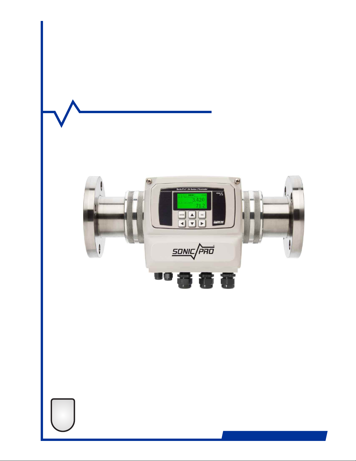
SONIC-PRO
Series S4
d
ProSeries
2
TWO-YEAR
WARRANTY
Ultrasonic Flow Meter
Installation and Operating Manual
ProSeries
by Blue-White Ind.
Industries, Ltd.
Industries, Ltd.
d
Page 2
Page 1
Safety Precautions
Thank you for purchasing the Sonic-Pro series S4 ultrasonic flowmeter.
This instruction manual provides important information regarding the safe installation,
operation and maintenance of the flowmeter. Please read it carefully before attempting to
install or operate the meter. A copy of this manual should be kept by the operator. Extra
copies of this manual are available from your supplier or directly from the manufacturer.
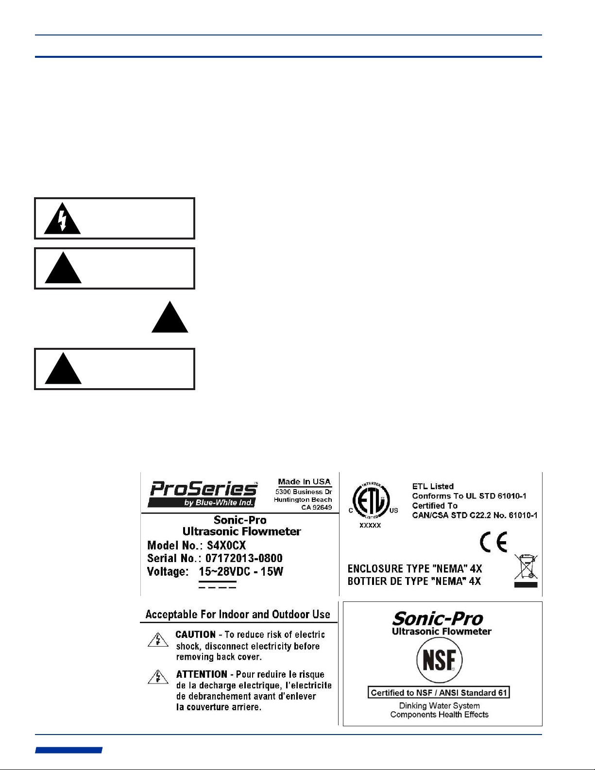
The following important symbols are used throughout this manual and on labeling affixed to
the flowmeter:
CAUTION
risk of electric shock
Sonic-Pro
This symbol identifies a risk of electric shock where the possibility of injury or
death is present.
!
!
CAUTION
risk of danger
CAUTION
risk of danger
QUESTIONS REGARDING THE SAFE USE OF THIS PRODUCT AND OTHER TECHNICAL
ASSISTANCE MAY BE DIRECTED TO:
!
This symbol identifies a risk of injury or death is present.
In all cases, when this symbol is used on labeling affixed to the flowmeter, the
documentation needs to be consulted to find out the nature of the potential
HAZARD and any actions which have to be taken.
If the equipment is used in a manner not specified by this instruction manual,
the protection provided by the equipment may be impaired.
Blue-White Industries
714-893-8529
techsupport @blue-white.com
ProSeries
by Blue-White Ind.
Industries, Ltd.
Industries, Ltd.
d
Page 3
Sonic-Pro
Page 2
1.0 Product Overview
The Sonic-Pro series S4 Ultrasonic Flow Meter can measure fluid flow in water and many
other clean fluids with sound speeds that are similar to water. The meter measures fluid flow
using the Transit Time method. The S4 ultrasonic sound transducers do not touch the
process fluid and there are no moving parts. This method of flow measurement is safe, nonintrusive and requires little to no maintenance.
The fluid being measured must be relatively “clean” to enable the sound waves to complete
their circuit. The maximum amount of particles should not exceed . The 5% (50,000 ppm)
meter cannot measure through air. Air bubbles and excessive turbulence will disrupt the
sound beam.
The angle of the sound beam, as it travels through a material, is effected by the speed that
sound travels through that material. As the sound speed changes, the angle changes. Sound
travels through 68 F clean water at a speed of 1,481 meters per sec. The S4 ultrasonic
sound transducers are factory positioned for a fluid sound speed of 1,500 m/sec +/- 100.
They cannot be adjusted in the field.
Water that contains concentrations of other chemicals, or other chemicals entirely, may be
acceptable provided the chemical does not change the sound speed (SOS) more than
approximately +/- 100 meters per second and provided the fluid allows the sound beam to
pass through unimpeded. Note that the speed that sound travels through the fluid is effected
by changes in the fluid’s density.
O
The S4 includes a 6-button user interface that can be used to configure the meter. The
optimum sound speed setpoint can be adjusted by the user within the range of 1,500 m/sec
+/- 100 m/sec.
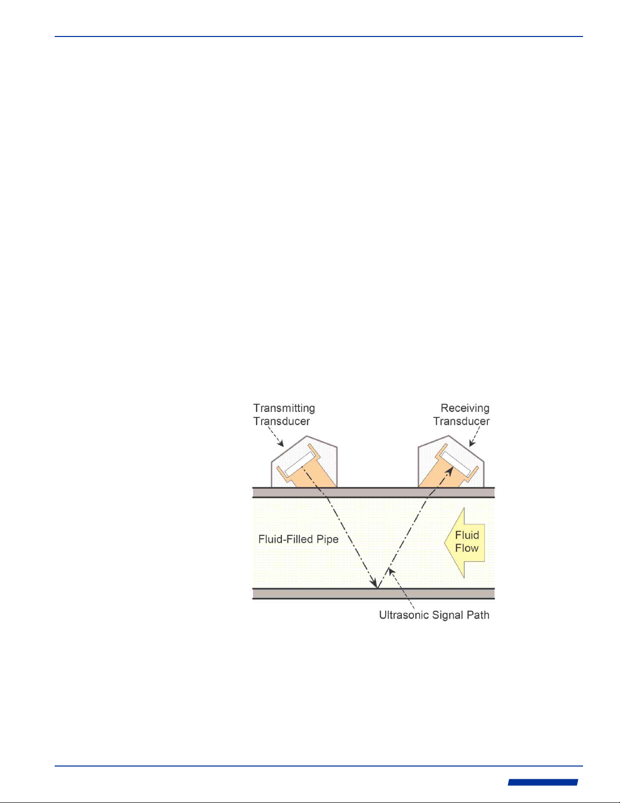
TRANSIT TIME MEASUREMENT PRINCIPLE
During operation in the Transit Time measurement method, a short ultrasonic signal burst
passes first in one direction and then in the other between two transducers separated along
the length of the pipe. When traveling in the same direction as fluid flow, the burst is carried
along by the fluid and arrives earlier as a result. When traveling against fluid flow, the burst is
held back by the fluid and arrives later. The SPU ( measures this Signal Processing Unit)
difference in time-of-flight in the two directions. From this, the actual time-of-flights, the
distance traveled in the fluid and the angle of the ultrasonic signal path, it calculates the fluid
velocity.
ProSeries
by Blue-White Ind.
Industries, Ltd.
Industries, Ltd.
d
Page 4
Page 3
Sonic-Pro
2.0 Flowmeter SPU Installation
2.1
Unpacking
2.2
Mounting
Location
!
risk of danger
The Sonic-Pro Flowmeter is shipped with the following items:
! Sonic-Pro Flowmeter SPU (Signal Processing Unit)
! Sonic-Pro Inline Pipe Fitting
! Enclosure Mounting Hardware (not included in sensor mounted units)
2 mounting plates
4 mounting plate screws (10-32 x .50”)
2 wall mounting screws (#10 x 1.00”)
1 pipe mounting clamp (maximum pipe diameter 10”)
! Instruction Manual
The Sonic-Pro was designed to be installed and operated by qualified personnel only. Do not
attempt to install or operate the meter if you are unsure. Seek qualified assistance. Please
note that warranty coverage does not include damage due to misuse or improper
installation.
If remote mounting the SPU, select a mounting location that is within reach of the transducer
cables and power supply. The transducer cable must not be cut or modified. Note that the
Sonic-Pro can accurately measure flow from either direction.
The SPU can be mounted on a wall or on a horizontal or vertical run of pipe. Although the
Sonic-Pro is designed to withstand outdoor conditions. A cool, dry location, where the unit
can be easily monitored is recommended. Special ventilation is not required.
CAUTION
Do not position the equipment so that it is difficult to disconnect the power
supply cord.
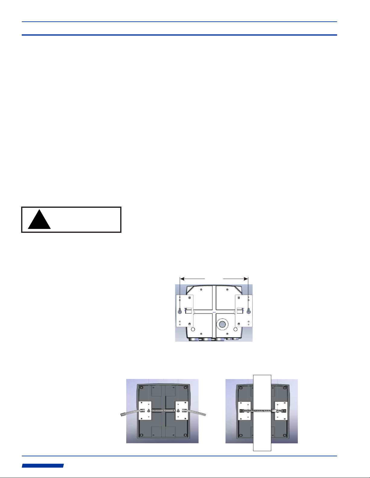
2.3
Wall or Pipe
Mounting
When the SPU is not mounted directly to the Inline Fitting, the SPU must be installed on a
solid, secure surface such as a solid wall, panel, wall studs, etc. DO NOT install the meter
on drywall with anchor bolts.
8.00 in
[20.3 cm]
The SPU can be mounted on horizontal or vertical pipe. The pipe must be secure and of
sufficient strength to support the weight of the SPU.
ProSeries
by Blue-White Ind.
Industries, Ltd.
Industries, Ltd.
d
Page 5
Sonic-Pro
Page 4
3.0 Ultrasonic Transducer Installation
3.1
Pipe Fitting/
Transducer
Installation
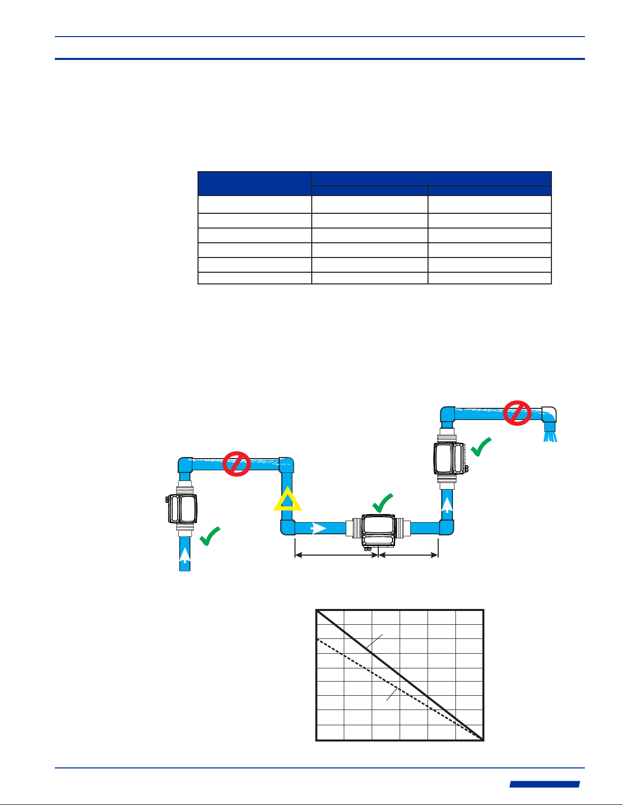
Minimum Straight Pipe Length Requirements
The Sonic-Pro’s sound wave beam is only affected by fluid that actually passes through the
beam and therefore, the meter will not measure with high accuracy if the fluid velocity is not
consistent across the entire pipe diameter. Flow disturbances such as pumps, elbows, tees,
and valves in the flow stream can cause swirl patterns and vortices that will affect the
measurement accuracy or disrupt flow measurement capability. Install the transducers on a
straight run of pipe as far as possible from any disturbances. The distance required for high
accuracy will depend on the type of disturbance.
Type of Disturbance
Flange
Reducer
o
90 Elbow
o
Two 90 Elbows - 1 Direction
o
Two 90 Elbows - 2 Directions
Gate valve or Pump
Upstream from Transducers
5 x Nominal Pipe Size
7 x Nominal Pipe Size 5 x Nominal Pipe Size
10 x Nominal Pipe Size 5 x Nominal Pipe Size
15 x Nominal Pipe Size 5 x Nominal Pipe Size
20 x Nominal Pipe Size 5 x Nominal Pipe Size
25 x Nominal Pipe Size 5 x Nominal Pipe Size
Straight Lengths of Pipe Required
Downstream from Transducers
5 x Nominal Pipe Size
Transducer Mounting Requirements
!
The meter can be mounted on horizontal or vertical runs of pipe.
!
Mounting anywhere around the diameter of vertical pipe is acceptable, however, the pipe
must be completely full of fluid at all times.
!
Back pressure is required on downward flows to ensure a full pipe.
!
See the minimum straight length of pipe requirement chart above.
!
Related piping must be independently supported. The meter should not be allowed to
support the weight of related piping.
NO
Pipe must be full
NO
Air could be trapped
Down flows
must have
back pressure
OK
!
160° F (71° C)
150° F (65° C)
140° F (60° C)
130° F (54° C)
120° F (49° C)
110° F (43° C)
100° F (38° C)
TEMPERATURE F (C)
90° F (32° C)
80° F (27° C)
70° F (21° C)
OK
L >= 5DL >= 10D
See minimum straight length requirements above
INLINE PIPE FITTING
TEMPERATURE VS PRESSURE
HDPE and 316SS Adapters
PVC Adapters
0
50 100
WORKING PRESSURE (PSI/g)
150
200 250
300
OK
ProSeries
by Blue-White Ind.
Industries, Ltd.
Industries, Ltd.
d
Page 6
Page 5
Sonic-Pro
4.0 Wiring Installation
4.1
Electrical
Connections
4.2
Cable Gland
Liquid-Tight
Connections
The meter must be powered by 15 to 28 volts DC. Depending on the model ordered, an
AC/DC plug-in transformer may have been be supplied for this purpose. See the diagram
below for wiring of output signals, communications signals and process control relays.
The transducer cable length is factory fixed. Do not attempt to modify the length of these
cables. Various cable lengths are available from the factory. Contact the factory if you need
assistance.
Shielded cable is recommended for signal output connections.
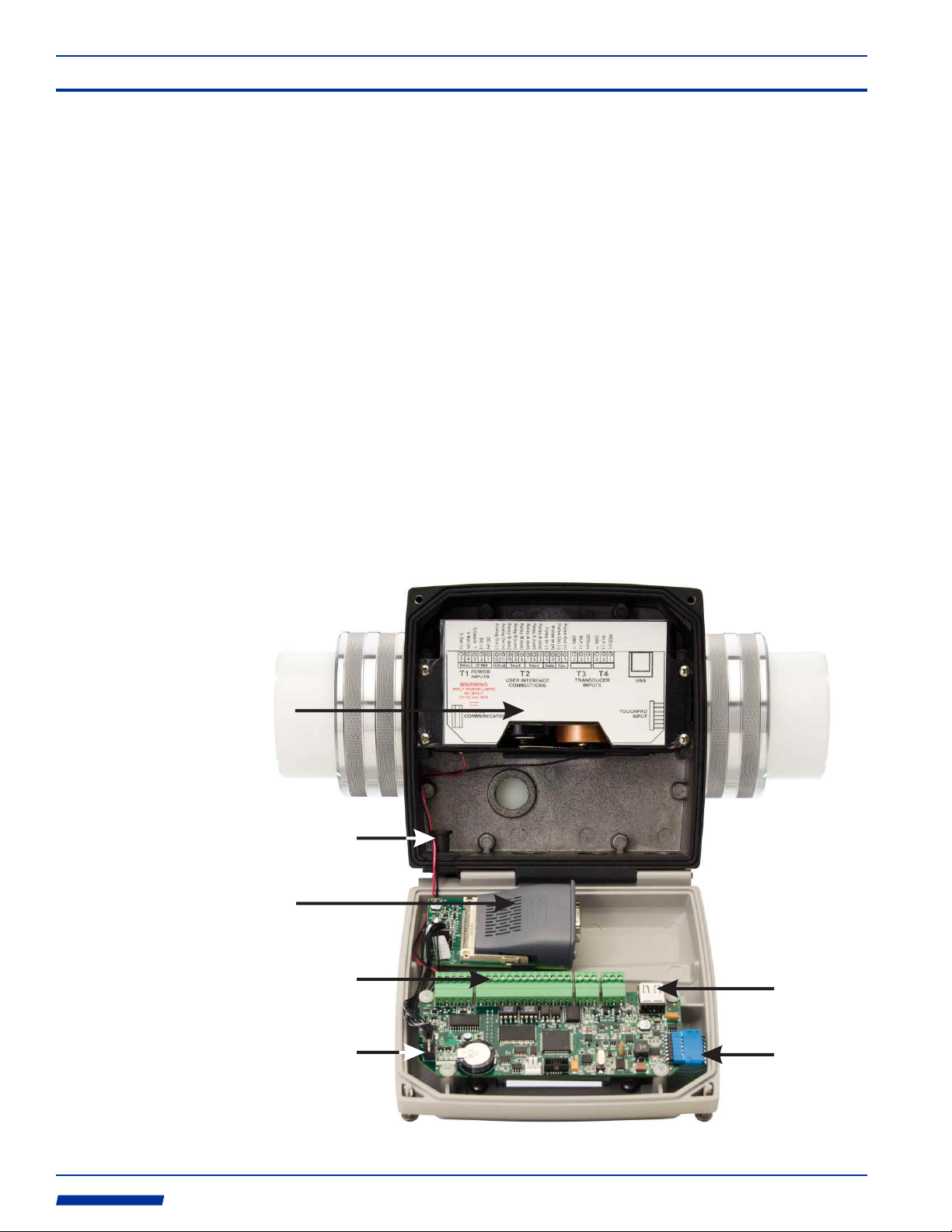
The Sonic-Pro SPU wiring compartment is equipped with:
Ÿ Three liquid-tight cable gland connectors for cable diameter from .200 to .394 inches (5.1
to 10.0 mm).
Ÿ Two liquid-tight cable gland connectors cable for diameters from .118 to .255 inches (3.0 to
6.5 mm).
Ÿ One communications cable liquid-tight cable gland grommet for cable diameters from .190
to .205 inches. It is provided for any one of the following cable types:
Ethernet Cable
RS-232 serial cable
Note that the blank grommet plug should be used when the communications cable grommet
is not required.
4.3
Wiring
Compartment
Back-up
Battery
Compartment
(4 D cells -
not included)
Communications
Cable Grommet
Optional
Communications
Circuitry
Wiring Terminals
Main PCB
Transducer A Transducer B
USB
Connection
ProSeries
by Blue-White Ind.
Industries, Ltd.
Industries, Ltd.
Communications
Circuitry
Input Socket
d
Touchpad
Connection
Page 7
Sonic-Pro
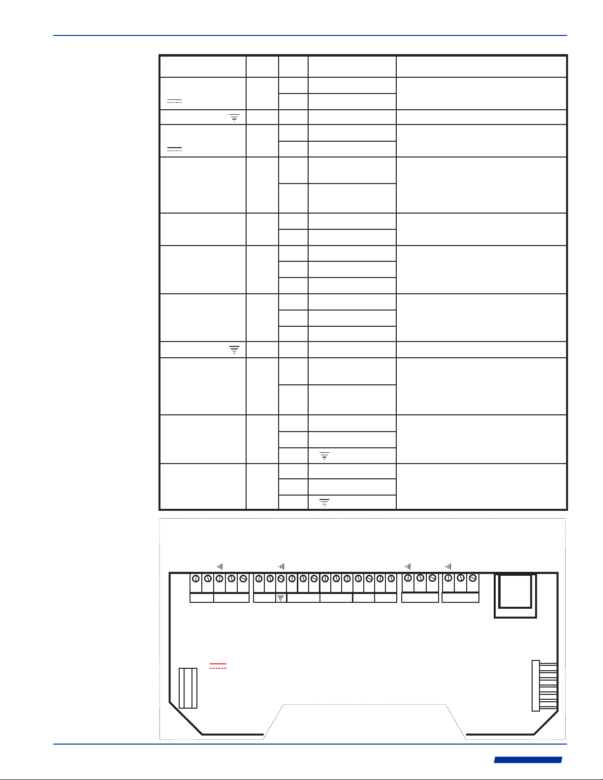
4.4
Wiring
Terminals
The terminal blocks are plug type capable of accepting 14 to 30 AWG wire.
FUNCTION TERM PIN # DESCRIPTION
POWER INPUT:
Primary power
Chassis Ground
POWER INPUT:
Battery Back-up power
PULSE FREQUENCY
OUTPUT:
Open Collector
PADDLEWHEEL
SENSOR INPUT:
AC Sine wave
RELAY ‘A’ OUTPUT
RELAY ‘B’ OUTPUT
Chassis Ground
ANALOG OUTPUT:
4-20 mA
TRANSDUCER
INPUT:
Transducer A
TRANSDUCER
INPUT:
Transducer B
T1
T1
T1
T2
T2
T2
T2
T2
T2
T3
T4
1
2
3
4
5
1
2
3
4
5
6
7
8
9
10
11
12
13
1
2
3
1
2
3
RATING
(+) 15-28 Vdc
(-) 15-28 Vdc
Ground
(+) Positive
(-) Negative
(+) Positive
(-) Negative
(+) Positive
(-) Negative
Normally Open
Common
Normally Closed
Normally Open
Common
Normally Closed
Ground
(+) Positive
(-) Negative
(+) Red
(-) Black
Green or Bare
(+) Red
(-) Black
Green or Bare
15-28Vdc, 400mA max
4 D cell size batteries
(Alkaline batteries only are acceptable)
Type: Open collector w/ internal 1 K pull-up to 5V.
Can be pulled up to 30V @ 10mA (3K pull-up)
Duty Cycle: 50%+/-5%
Frequency Range: 0-1000 Hz
Resolution: 1 Hz
Accuracy: 0.5% F.S.
Blue-White model FC sensor.
100mVp-p, 10 to 350Hz
Type: FORM C
Load capacity: 30V, 100mA max (ext. supplied)
Type: FORM C
Load capacity: 30V, 100mA max (ext. supplied)
Current output: 4-20 mADC, isolated.
Max Load Impedance: 1K ohm
Power: Internal
Resolution: 12 bits
Accuracy: Less than 0.1% F.S.
Update Rate: 1.0 s
Page 6
Analog Out (+)
Chassis
Analog Out (-)
V Bat (+)
V Bat (-)
5 4 3 2 1 10 9 8 7 6 5 4 3 2 1 3 2 13 2 1131211
Battery
T1 T2 T3 T4
WARNING
INPUT POWER LIMITS
DC INPUT
15~28 Vdc-15W
ANYBUS
COMMUNICATIONS
DC (-)
DC PWR
POWER
INPUTS
DC (+)
4-20 mA
Relay B (n/c)
Relay B (n/o)
Relay B (com)
Relay A (n/c)
Relay A (com)
Chassis
Relay B
USER INTERFACE
CONNECTIONS
Relay A
Relay A (n/o)
Pulse In (-)
Paddle
Pulse Out (-)
Pulse Out (+)
Pulse In (+)
Pulse
RED (+)
GRN
BLK (-)
Transducer A
TRANSDUCER
INPUTS
RED (+)
GRN
BLK (-)
Transducer B
USB
TOUCHPAD
INPUT
ProSeries
by Blue-White Ind.
Industries, Ltd.
Industries, Ltd.
d
Page 8
Page 7
Sonic-Pro
5.0 Operation
5.1
Power On
5.1.1
Battery Powered
operation
1. If power is present on Terminal T1 pins 1 & 2, the meter is always powered on.
2. If power is removed from Terminal T1 pins 1 & 2, and 4 D-Cell batteries are installed on
Terminal T1 pins 4 & 5, the meter will stay on (battery back-up). Under these conditions, the
meter can be turned on/off by pressing and holding the front panel ENTER button for three
seconds.
3. If power is only present on the battery Terminal T1 pins 4 & 5, then the meter can be
turned on/off by pressing and holding the front panel ENTER button for three seconds.
Operating time is limited when powered by batteries only.
While the batteries pack is provided primarily as back-up power, the S4 meter can be
operated solely with 4 D-cell batteries (not included). The meter can be configured to sleep
between measurements in order to conserve power. The approximate battery life is .....
Continuous Running
The following meter features are disabled during battery operation:
Ÿ Communications Module
Ÿ Analog output
Ÿ Pulse Frequency Output
10 / 10
128 Hr72 Hr 310 Hr 377 Hr 450 Hr
On / Sleep Time (seconds)
10 / 100 5 / 100 3 / 268
5.2
Run Screen
5.2.1
Fault Screen
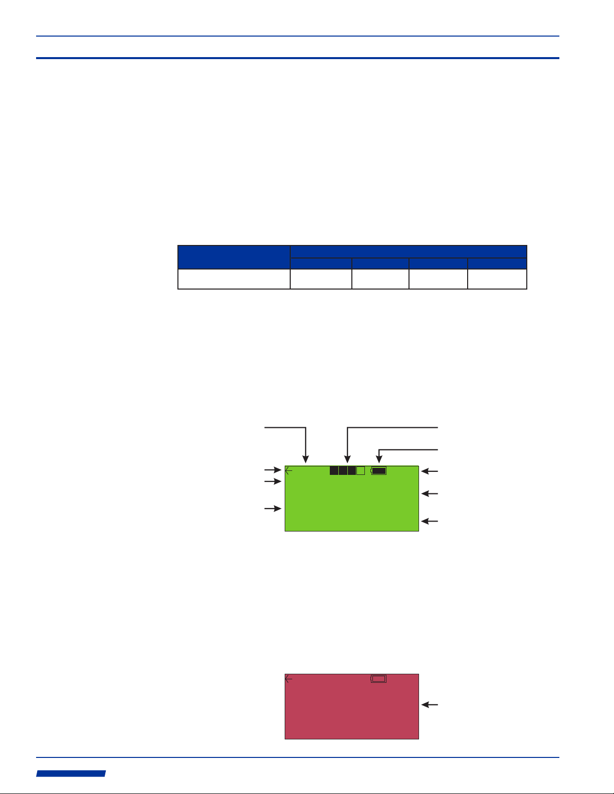
When the S4 is factory ordered with a pipe fitting/transducer, the pipe fitting data and the
default display feature parameters are pre-configured. When power is applied and there is
water in the pipe fitting, the following RUN display screen will be displayed.
Transducer Separation
Distance
Flow Direction
Flow Rate Units
0.28”
U.S Gallons/Min
25
Total Units
Ÿ Press the ENTER button to enter the menu system.
Ÿ Press the ESC button to clear the flow total to zero (if enabled in configuration).
Ÿ Press the up arrow p to toggle the flow rate to linear Feet/Sec., Meters/sec and back to
the configured user units of measure.
There are three possible FAULT indicator screens.
Ÿ FAULT 11 - Transducers are not connected or there is no fluid in the pipe.
Ÿ FAULT 12 - The allowable SOS (Speed Of Sound) error set-point has been exceeded.
Ÿ FAULT 21 - The configuration data is not valid.
U.S Gallons
0.28”
U.S Gallons/Min
XDCR Disc.
U.S Gallons
F-11
105
.
.
0”
1482
05469
Measurement Reliability
Battery Life
Measured Sound Speed
Flow rate
Flow Total
(press and hold ESC to clear)
Error Code
ProSeries
by Blue-White Ind.
Industries, Ltd.
Industries, Ltd.
0
d
Page 9
Sonic-Pro
5.3
Menu
Navigation
Page 8
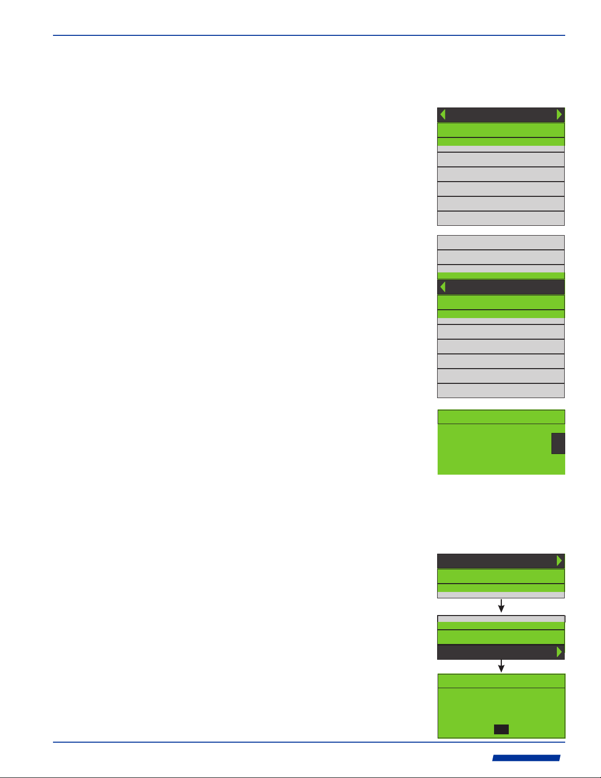
The Configuration Menu
From the RUN mode, press and release the ENTER button to enter the CONFIGURATION
menu. The following menu will be displayed:
5.3.1
Selecting and
Entering Menus
5.3.2
Selecting Optional
Items
Ÿ Press up arrow p or down arrow q to select menu items.
The selected item will be highlighted.
Ÿ Press right arrow u or ENTER to enter the selected menu.
Ÿ Press left arrow t to go back one menu.
Ÿ Notice the gray area. These menu items are hidden from
view. Press the up arrow p or down arrow q to display
hidden menu items.
Ÿ Press up arrow p or down arrow q to select optional
configuration items. The selected item will be highlighted.
Ÿ Press left arrow t or ENTER to choose the selected
optional item and return to the menu heading.
Paddle Wheel
XDCR Settings
Meter Settings
Output Settings
Clock
Calibration
Global Config.
About
U.S. Gallons
Ounces
U.S. Barrels Liq.
U.S. Barrels Oil
Cubic Feet
Acre Feet
Imperial Gallons
Cubic Meters
Liters
Milliliters
FR Custom V/Gal
5.3.3
Inputting Data
5.3.4
Save Configuration
Ÿ Press right arrow u or left arrow t to select a digit to
modify. Pressing the left arrow t will create additional
numbers to the left.
Ÿ Press up arrow p to increase or down arrow q to
decrease the value.
Ÿ Press ENTER to confirm the modifications and return to
the menu heading.
Ÿ Press ESC to cancel the modifications and return to the
menu heading.
Ÿ Press left arrow t to exit to the main menu.
Ÿ Press down arrow q to Highlight Save Config.
Ÿ Press right arrow u or ENTER to save the configuration
changes.
Ÿ Press ENTER to confirm the configuration changes have
been saved.
Ÿ Press up arrow p to RUN.
Ÿ Press right arrow u or ENTER to enter the RUN mode,
Enter Value
9.1000
0
Configuration
XDCR Settings
Save Config.
Configuration
XDCR Settings
Save Config.
Configuration
Configuration Saved!
OK
ProSeries
by Blue-White Ind.
Industries, Ltd.
Industries, Ltd.
d
Page 10
Page 9
Sonic-Pro
6.0 Configuration
The S4’s SPU can be used with a Paddle Wheel type sensor that outputs an AC Sine wave or
an Ultrasonic type sensor.
6.1
Configure the
SPU for a
Paddle Wheel
Sensor
6.2
Configure the
SPU for an
Ultrasonic
Inline Pipe
Fitting
Configuration
Paddle Wheel
When using an AC Sine wave Paddle Wheel type flow sensor and pipe fitting, the installer
must input the pipe fitting K-factor. The K-Factor is the total number of pulses output by the
sensor per gallon of fluid flow for a specific pipe fitting. The K-factor is different for each pipe
fitting. See the paddle wheel sensor’s instruction manual for a list of pipe fitting K-factors.
Configuration
Run
Save Config
Paddle Wheel
K-Factor
Enter Value
0.0000
When using Ultrasonic Transducers (XDCR), if the SPU and the Ultrasonic Inline Pipe
Fitting was shipped from the factory as a single model number, the SPU is pre-configured
with the proper model number and calibration constants shown on the calibration label
attached to the pipe fitting. If the pipe fitting was sold separately, the SPU will need to be
configured with the following data shown on the calibration label:
1. Measurement Units. The default value for all inline fittings is ENGLISH.
2. Model. The default value for all inline fittings is “C”.
3. Mount Method. The default value for all inline fittings is “V”.
4. Cable Length. Enter the length in feet. The available cable lengths are: 1 foot (SPU
mounted directly on the pipe fitting), 10, 25, 50 or 100 feet.
5. Flow Direction -> Direction. The default value for all inline fittings is “A -> B”.
6. Flow Direction -> Settings. Each flow direction has a unique SCALING and ZERO
VALUE number shown on the pipe fitting calibration label. Note that the ZERO number
may be POSITIVE or NEGATIVE.
7. Pipe Outside Diameter. Shown on the pipe fitting calibration label. Do not use your
inlet/outlet pipe size.
8. Pipe Wall Thickness. Shown on the pipe fitting calibration label. Do not use your
nominal pipe size.
9. Pipe Material. Shown on the pipe fitting calibration label. Do not use your inlet/outlet pipe
material.
10. Fluid Type. Select WATER or CUSTOM.
11. Fluid SOS. If WATER is selected, it is not necessary to input a fluid SOS. If “CUSTOM”
fluid type is selected, the Speed of Sound (SOS) for the custom fluid must be entered
manually. Note that the SOS must be within the pipe fitting’s SOS range.
Run
Save Config
ProSeries
by Blue-White Ind.
Industries, Ltd.
Industries, Ltd.
XDCR Settings
d
Meas. Units
Transducer
Pipe
Fluid Fluid Type
ENGLISH
Mount Method
Cable Length(ft)
Flow Direction
Pipe Outside Dia.
Pipe Wall Thick.
Pipe Material
Pipe SOS
Fluid SOS
METRIC
Model
C
I
J
V
W
Enter Value
Direction
Settings
Enter Value
0.0000
Enter Value
0.0000
Enter Value
0.0000
Enter Value
10
0000
A -> B
B -> A
A -> B
B -> A
Custom
HDPE
Custom
Water
Enter Value
0.0000 0.0000
Scaling(A->B)
Zero(A->B)
Scaling(B->A)
Zero(B->A)
Zero Value(B->A)
Sign(B->A)
Positive
Negative
Enter Value
Zero Value(A->B)
Sign(A->B)
Positive
Negative
Enter Value
0.0000
Enter Value
0.0000
Page 11

Sonic-Pro
6.2.1
Measurement
Units
Menu
Page 10
Select ENGLISH when entering the Pipe Outside Diameter and Pipe Wall Thickness
dimensional data in Inches. Select METRIC when entering pipe the Outside Diameter and
Pipe Wall Thickness dimensional data in millimeters.
Note that the factory default units is INCHES. These dimensions are shown on the
Calibration Detail label affixed to the pipe fitting:
6.2.2
Transducer
Menu
Meas. Units
Transducer
ENGLISH
METRIC
Model
Mount Method
Cable Length(ft)
Flow Direction
CALIBRATION DETAIL LABEL
C
I
J
V
W
Enter Value
10
Direction
Settings
A -> B
B -> A
A -> B
B -> A
Scaling(A->B)
Scaling(B->A)
Zero Value(B->A)
Enter Value
0.975 0.455
Zero(A->B)
Zero(B->A)
Sign(B->A)
Positive
Negative
Enter Value
Zero Value(A->B)
Sign(A->B)
Positive
Negative
Enter Value
0.975
Enter Value
0.455
6.2.2.1
Transducer
Model
6.2.2.2
Transducer
Mount Method
6.2.2.3
Transducer
Cable Length
There are three transducer MODELS available to select. When using the S4 Inline Pipe
Fitting/Transducer, select model C. See the model number ordering matrix for additional
transducer model options.
C
I
Transducer
Model
J
The transducers are factory set inside the pipe fitting and cannot be moved. Select the mount
method that is shown on the Calibration Detail label affixed to the pipe fitting.
Transducer
Model
Mount Method
V
W
Enter the transducer cable length. The available length options are:
1 = Sensor Mounted Display (no cable)
10 = 10 ft cable, transducer cable model number option “A”
25 = 25 ft cable, transducer cable model number option “B”
50 = 50 ft cable, transducer cable model number option “C”
100 = 100 ft cable, transducer cable model number option “D”
Transducer
Model
Mount Method
Cable Length(ft)
Enter Value
10
ProSeries
by Blue-White Ind.
Industries, Ltd.
Industries, Ltd.
d
Page 12

Page 11
6.2.2.4
Fluid Flow
Direction
Sonic-Pro
The relative flow direction is shown on the Calibration Detail label affixed to the pipe fitting.
Transducer
Model
Mount Method
Cable Length(ft)
Flow Direction
Direction
A -> B
B -> A
6.2.2.5
Fluid Flow
Direction
(CAL Settings)
Each of the flow directions (A to B and B to A) have a Scaling Factor and either a positive or
negative Zero Factor associated with it. The correct factors are shown on the Calibration
Detail label affixed to the ultrasonic flow sensor pipe fitting.
These are factory calibration factors that should not be changed without first
contacting the factory for technical assistance.
Transducer
Model
Mount Method
Cable Length(ft)
Flow Direction
Direction
Settings
A -> B
B -> A
Enter Value
0.975 0.455
Scaling(A->B)
Zero(A->B)
Scaling(B->A)
Zero(B->A)
Zero Value(B->A)
Sign(B->A)
Positive
Negative
Enter Value
Zero Value(A->B)
Sign(A->B)
Positive
Negative
Enter Value
0.975
Enter Value
0.455
6.2.3
Pipe
Menu
ProSeries
by Blue-White Ind.
Industries, Ltd.
Industries, Ltd.
CALIBRATION DETAIL LABEL
Each pipe fitting has a specific Pipe Outside Dia., Pipe Wall Thick., Pipe Material and Pipe
SOS (Speed Of Sound) associated with it. The correct factors are shown on the Calibration
Detail label affixed to the ultrasonic flow sensor pipe fitting.
These are factory calibration factors that should not be changed without first
contacting the factory for technical assistance.
Pipe
d
Pipe Outside Dia.
Pipe Wall Thick.
Pipe Material
Pipe SOS
Enter Value
0.0000
Enter Value
0.0000
Enter Value
0.0000
Custom
HDPE
Page 13

Sonic-Pro
6.2.4
Fluid
Menu
Page 12
The sound transducers are located in the S4 pipe fitting. They are carefully positioned at the
factory for use with water at 68 degrees F which has a SOS (Speed Of Sound) of 1481
meters per second. (see page 28 for water SOS chart). The transducer placement cannot be
adjusted in the field. As the fluid’s sound speed moves away from the target Fluid SOS,
measurements become more difficult. If the speed that sound travels through the fluid is very
different than that of water, the meter will not function. The acceptable SOS range is from
1,400 to 1,600 m/sec.
The meter will display the SOS of the fluid being measured in the upper right hand corner of
the display.
Successful measurements are possible with fluids other than water provided the fluid’s SOS
is within the acceptable range and there are not too many particles or other sound blocking or
reflecting contaminants in the fluid which can inhibit the sound beam.
The target Fluid SOS value can be adjusted to maximize the meter’s ability to measure the
fluid. The chart below provides the sound speeds of a number of chemicals of specific
concentrations at specific temperatures. Diluted chemicals will have a different sound speed.
Select Custom from the Fluid Type menu, then input the SOS fluid in the Fluid SOS menu.
Fluid Fluid Type
Fluid SOS
Enter Value
0000
Custom
Water
Fluid Sound Speeds
Fluid
Water
Water
Water
Sea Water
Aluminum Sulfate 10% (Alum)
Ethylene Glycol (50% in water)
Gasoline
Hydrochloric Acid 32%
Hydrogen Peroxide 31%
Milk
Oil, Diesel
Oil, Motor (SAE 30)
Oil, Mineral
Potassium Hydroxide 50%
Sodium Hypochlorite 12%
Sulfuric Acid 96%
Sound Speed (meters/sec)
1403
1481
1543
1520
1900
1578
1250
1581
1530
1548
1250
1487
1431
2800
1835
1260
o o
Temp. F ( C)
32 (0)
68 (20)
212 (100)
68 (20)
68 (20)
77 (25)
77 (25)
68 (20)
68 (20)
77 (25)
77 (25)
68 (20)
77 (25)
68 (20)
68 (20)
68 (20)
ProSeries
by Blue-White Ind.
Industries, Ltd.
Industries, Ltd.
d
Page 14

Page 13
6.3
Configure the
SPU Meter
Settings
Sonic-Pro
In the Meter Settings menu, the data logging functions and the display features can be
configured.
Meter Settings
Logging
Display
Log Interval(s)
Rate Set Point 1
Rate Set Point 2
Tot. Set Point 1
Tot. Set Point 2
Tot. Set Point 3
Tot. Set Point 4
Tot. Set Point 5
Copy Logs
Delete Logs
Flow Rate Volume Units
Enter Value
Enter Value
Enter Value
Enter Value
Time Units
Fl. Rate Decimal
0.0000
0.0000
0.0000
0.0000
Enter Value
0.0000
Enter Value
0.0000
Enter Value
0.0000
Enter Value
0.0000
Seconds
Minutes
Hours
Days
Enter Value
U.S. Gallons
Ounces
U.S. Barrels Liq.
U.S. Barrels Oil
Cubic Feet
Acre Feet
Imperial Gallons
0
Cubic Meters
Liters
Milliliters
FR Custom V/Gal
Enter Value
0
Totalizer Volume Units
Fl. Total Decimal
Flow Average(s)
Enable Tot. Clear?
Low Fl. Cut-Off
High Fl. Cut-Off
Scaling Off-set
Zero Off-set
SOS Fault Window
Sleep Time(s)
Enter Value
Yes
Enter Value
Enter Value
Enter Value
FR Offset
Sign
Enter Value
Enter Value
No
999
1.0000
0
0
10
0
Enter Value
Enter Value
0.0000
Positive
Negative
U.S. Gallons
Ounces
U.S. Barrels Liq.
0
U.S. Barrels Oil
Cubic Feet
Acre Feet
Imperial Gallons
Cubic Meters
Liters
Milliliters
FR Custom V/Gal
Enter Value
0
ProSeries
by Blue-White Ind.
Industries, Ltd.
Industries, Ltd.
d
Page 15

Sonic-Pro
6.3.1
Logging
Menu
Page 14
Data logs are stored in the meter’s internal memory in a space delimited .TXT file that can
easily be copied to a removable USB flash drive located on the main circuit board. Each log
file includes the date and time, the flow rate (FR) and the flow total (TL). A total of 191,800
logs can be stored.
2013/12/29 09:15:00 FR 0.0000 TL 0.00
The Log Interval determines the number of seconds from 1 - 999,999 that the meter will wait
between logs.
If a value is entered into Rate Set Point 1, a new log will be generated every 60 seconds
while the measured rate of flow is greater than the configured value.
If a value is entered into Rate Set Point 2, a new log will be generated every 60 seconds
while the measured rate of flow is less than the configured value.
If a value is entered into any Tot. Set Point (1, 2, 3, 4 or 5), a new log will be generated
when the total accumulated flow value is equal to the configured value.
To access the log entries, you must copy the logs onto a USB flash drive and transfer the file
to a computer for reading. To copy all of the log entries, open the enclosure and insert a USB
flash drive. Highlight Copy Logs press either right arrow u or ENTER. When copying logs,
all of the logs must be copied. You may not copy only selected logs.
To delete ALL of the log entries, highlight Delete Logs then press either right arrow u or
ENTER. You may not delete only selected logs. All logs must be deleted.
Logging
Log Interval(s)
Rate Set Point 1
Rate Set Point 2
Tot. Set Point 1
Tot. Set Point 2
Tot. Set Point 3
Tot. Set Point 4
Tot. Set Point 5
Copy Logs
Delete Logs
Enter Value
0.0000
Enter Value
0.0000
Enter Value
0.0000
Enter Value
0.0000
Enter Value
0.0000
Enter Value
0.0000
Enter Value
0.0000
Enter Value
0.0000
ProSeries
by Blue-White Ind.
Industries, Ltd.
Industries, Ltd.
d
Page 16

Page 15
6.3.2
Display
Menu
Sonic-Pro
In the DISPLAY menu, the following features may be configured:
! Flow Rate - Volume Units
! Flow Rate - Time Units
! Flow Rate - Decimal Point Location
! Totalizer - Volume Units
! Totalizer - Decimal Point Location
! Flow Rate Averaging
! Enable/Disable clearing the totalizer from the front panel
! Low Flow Rate Cut-Off
! High Flow Rate Cut-Off
! Scaling Offset
! Zero Offset
! SOS Fault Window
! Sleep Time
Display
Flow Rate Volume Units
Time Units
Fl. Rate Decimal
Totalizer Volume Units
Fl. Total Decimal
Flow Average(s)
Enable Tot. Clear?
Low Fl. Cut-Off
High Fl. Cut-Off
Scaling Off-set
Zero Off-set
SOS Fault Window
Sleep Time(s)
Enter Value
Yes
Enter Value
Enter Value
Enter Value
FR Offset
Sign
Enter Value
Enter Value
No
999
1.0000
10
0
0
0
Seconds
Minutes
Hours
Days
Enter Value
Enter Value
Enter Value
0.0000
Positive
Negative
U.S. Gallons
Ounces
U.S. Barrels Liq.
U.S. Barrels Oil
Cubic Feet
Acre Feet
Imperial Gallons
0
Cubic Meters
Liters
Milliliters
FR Custom V/Gal
U.S. Gallons
Ounces
U.S. Barrels Liq.
0
U.S. Barrels Oil
Cubic Feet
Acre Feet
Imperial Gallons
Cubic Meters
Liters
Milliliters
TOT Custom V/Gal
Enter Value
0
Enter Value
0
6.3.2.1
Flow Rate Menu
ProSeries
by Blue-White Ind.
Industries, Ltd.
Industries, Ltd.
d
In the Flow Rate menu, the Volume Units and Time Units may be selected from a list.
A custom volume unit may be created by selecting FR Custom V/Gal and entering the
number of gallons in the custom volume.
The Fl. Rate Decimal decimal point location may be set to a maximum of 5 digits.
Flow Rate Volume Units
Time Units
Fl. Rate Decimal
Seconds
Minutes
Hours
Days
Enter Value
U.S. Gallons
Ounces
U.S. Barrels Liq.
U.S. Barrels Oil
Cubic Feet
Acre Feet
Imperial Gallons
0
Cubic Meters
Liters
Milliliters
FR Custom V/Gal
Enter Value
0
Page 17

Sonic-Pro
6.3.2.2
Totalizer Menu
Page 16
In the Totalizer menu, the Volume Units may be selected from a list.
A custom volume unit may be created by selecting FR Custom V/Gal and entering the
number of gallons in the custom volume.
The Fl. Total Decimal decimal point location may be set to a maximum of 5 digits.
6.3.2.3
Flow Average
Setting
6.3.2.4
Clear Total
Setting
6.3.2.5
Low Flow Rate
Cut-off Setting
6.3.2.6
High Flow Rate
Cut-off Setting
Totalizer Volume Units
Fl. Total Decimal
Enter Value
U.S. Gallons
Ounces
U.S. Barrels Liq.
0
U.S. Barrels Oil
Cubic Feet
Acre Feet
Imperial Gallons
Cubic Meters
Liters
Milliliters
TOT Custom V/Gal
Enter Value
0
Flow Average(s) sets the running average period in seconds. Any number of seconds from 2
to 10 seconds is possible.
Flow Average(s)
Enter Value
0
Enable Tot. Clear? enables or disables the ability of the user to clear the accumulated total
flow by pressing the ESC button.
Enable Tot. Clear?
No
Yes
Low Fl. Cut-Off sets the minimum displayed flow rate. Calculated flow rate values less than
this value will be displayed as Zero and flow totalizing will not occur.
Low Fl. Cut-Off
Enter Value
0
High Fl. Cut-Off sets the maximum displayed flow rate. Calculated flow rate values greater
than this value will be displayed as the High Fl. Cut-Off value, totalizing will still occur.
High Fl. Cut-Off
Enter Value
999
6.3.2.7
Scaling Off-Set
Setting
6.3.2.8
Zero Off-Set
Setting
6.3.2.8
SOS
(Speed Of Sound)
Fault Window
Scaling Off-Set is a multiplier used to correct for flow inaccuracies. All flow rate values will
be multiplied by the Scaling Off-Set value and the result displayed and totaled.
Scaling Off-set
Enter Value
1.0000
Zero Off-Set is a factory calibration value used to offset the zero flow setpoint during the
initial calibration of the Ultrasonic Inline Pipe Fitting. The calibration value and sign should
match the ZERO: nnnn value and ZERO: +/-: xxx value shown on the Calibration Detail
label affixed to the pipe fitting.
These are factory calibration factors that should not be changed without first
contacting the factory for technical assistance.
Enter Value
Zero Off-set
FR Offset
Sign
0.0000
Positive
Negative
CALIBRATION DETAIL LABEL
The S4 will monitor the sound speed (SOS) of the measured fluid and report FAULT 12 if the
measured SOS exceeds the SOS Fault Window percentage value. The speed that sound
travels through the fluid will change if the density of the fluid changes (temperature change)
or if the fluid composition changes (chemical concentration, different chemicals, etc.). The
default value is 10%. The maximum allowable value is 50%.
SOS Fault Window
Enter Value
10
ProSeries
by Blue-White Ind.
Industries, Ltd.
Industries, Ltd.
d
Page 18

Page 17
6.3.2.9
Sleep Timer
Sonic-Pro
To conserve power, the S4 can be configured to “sleep” from 3 to 268 seconds per cycle. At
the end of each sleep cycle, the meter will “wake” for the number of seconds (from 2 to 10
seconds) as configured in the Flow Average feature, record data, and then return to sleep.
During the “wake” period, the display will remain blank.
The Flow Totalizer will estimate the amount of total fluid flow that would have been measured
while the meter was sleeping, using the following formula:
Total flow display value = T1 + (F1 + F2 / 2) x (N +1)
Where:
T1 = Last total before sleep
F1 = Last flow rate (units per second) before sleep
F2 = Flow rate average of the 1st second of wake-up (units per second)
N = Seconds of sleep (Sleep Timer Value)
note: the one second is added to the Sleep Time for accusation time at wake.
The sleep cycle can be interrupted by pressing the ENTER button.
Data logging cannot occur while sleeping. Logging will occur if the meter is “awake” and if it is
time to log data.
Sleep Time(s)
Enter Value
0
ProSeries
by Blue-White Ind.
Industries, Ltd.
Industries, Ltd.
d
Page 19

Sonic-Pro
6.4
Configure the
SPU Output
Settings
Page 18
In the Output Settings menu, the Analog 4-20mA, Pulse 0-1000 Hz, Contact Closures
and the Anybus Communications module functions can be configured.
Output Settings
Analog 4-20mA
Pulse 0-1000
Contact Closure
Anybus
Rate at Min Curr.
Min Analog O/P
Rate at Max Curr.
Max Analog O/P
Rate at Min Freq.
Min Frequency
Rate at Max Freq.
Max Frequency
Relay A
Relay B
Enter Value
0.0000
Enter Value
4
Enter Value
0.0000
Enter Value
20
Enter Value
0.0000
Enter Value
0
Enter Value
0.0000
Enter Value
1000
None A
Monitor Flow Rate
Monitor Totalizer
Faults A
None B
Monitor Flow Rate
Monitor Totalizer
Faults B
Type
Address
High Trigger A
High Release A
Low Trigger A
Low Release A
Time(s) A
Batch Amt. A
Contact Timer(s) A
High Trigger B
High Release B
Low Trigger B
Low Release B
Time(s) B
Batch Amt. B
Contact Timer(s) B
Profibus DPV1
Modbus RTU
Modbus TCP
Ethernet
Profinet
None
Profibus DPV1
Modbus RTU
Modbus TCP
Ethernet
Profinet
None
Enter Value
Enter Value
Enter Value
Enter Value
Enter Value
Enter Value
0
Enter Value
Enter Value
0
Enter Value
Enter Value
Enter Value
0
Enter Value
0
Enter Value
0
Enter Value
Enter Value
0
Enter Value
0
IP SET
192.168.234.123
OK CANCEL
IP SET
192.168.234.123
OK CANCEL
IP SET
192.168.234.123
OK CANCEL
ProSeries
0
0
0
0
0
0
0
0
0
by Blue-White Ind.
Industries, Ltd.
Industries, Ltd.
d
Page 20

Page 19
6.4.1
Analog
4-20mA
Output Menu
Sonic-Pro
An analog current output signal can be programmed within the range of 4-20mA.
Specify the flow rate at a minimum current (Rate at Min Curr.) and the corresponding
minimum analog current (Min Analog O/P).
Specify the flow rate at a maximum current (Rate at Max Curr.) and the corresponding
maximum analog current (Max Analog O/P).
The flow rates must not be the same. The current for the high flow rate may be smaller than
the current for the low flow rate in which case, the current will decrease with increasing flow
rate.
Flow rates are mapped to currents using a straight line through the two points specified.
Analog 4-20mA
Rate at Min Curr.
Min Analog O/P
Rate at Max Curr.
Max Analog O/P
Enter Value
0.0000
Enter Value
4
Enter Value
0.0000
Enter Value
20
6.4.2
Pulse
0-1000 Hz
Output Menu
A digital pulse output signal can be programmed within the range of 0-1000 Hz (pulses per
second).
Specify the flow rate at a minimum frequency (Rate at Min Freq.) and the corresponding
minimum frequency (Min Frequency).
Specify the flow rate at a maximum frequency (Rate at Max Freq.) and the corresponding
maximum frequency (Max Frequency).
The flow rates must not be the same. The frequency for the high flow rate may be smaller
than the frequency for the low flow rate in which case, the frequency will decrease with
increasing flow rate.
Flow rates are mapped to frequencies using a straight line through the two points specified.
Pulse 0-1000
Rate at Min Freq.
Min Frequency
Rate at Max Freq.
Max Frequency
Enter Value
0.0000
Enter Value
0
Enter Value
0.0000
Enter Value
1000
ProSeries
by Blue-White Ind.
Industries, Ltd.
Industries, Ltd.
d
Page 21

Sonic-Pro
6.4.3
Contact
Closure
Relay
Output Menu
Page 20
The S4 has two Form C relays. Each can be independently configured to energize when one
of the following conditions are met:
! A specific Flow Rate value is displayed, used for high, low or high/low range alarms.
! An Accumulated Total value has been measured. Used for triggering external equipment
when a configured batch amount is reached.
! A FAULT has occurred.
Contact Closure
Relay A
Relay B
None A
Monitor Flow Rate
Monitor Totalizer
Faults A
None B
Monitor Flow Rate
Monitor Totalizer
Faults B
High Trigger A
High Release A
Low Trigger A
Low Release A
Time(s) A
Batch Amt. A
Contact Timer(s) A
High Trigger B
High Release B
Low Trigger B
Low Release B
Time(s) B
Batch Amt. B
Contact Timer(s) B
Enter Value
0
Enter Value
0
Enter Value
0
Enter Value
0
Enter Value
0
Enter Value
0
Enter Value
0
Enter Value
0
Enter Value
0
Enter Value
0
Enter Value
0
Enter Value
0
Enter Value
0
Enter Value
0
6.4.3.1
CC Assigned to
Monitor Flow Rate
When in the Relay A or Relay B menu, selecting and then exiting the Monitor Flow Rate
menu will assigned that relay to monitor the rate of flow. The following functions are possible:
! Set a High Trigger flow rate value which when measured, will energize the relay.
! Set a High Release flow rate value which when measured, will de-energize the relay.
! Set a Low Trigger flow rate value which when measured, will energize the relay.
! Set a Low Release flow rate value which when measured, will de-energize the relay.
! Set a Time (s) in seconds (0-999) to delay energizing the relay when it is triggered.
When either of the relays are energized, the display back-light will turn blue.
When both the trigger and release values are configured for the same value, the relay will
latch. The user must press the ESC button to clear a latched relay.
Relay B
None B
Monitor Flow Rate
High Trigger B
High Release B
Low Trigger B
Low Release B
Time(s) B
Enter Value
Enter Value
Enter Value
Enter Value
Enter Value
0
0
0
0
0
ProSeries
by Blue-White Ind.
Industries, Ltd.
Industries, Ltd.
d
Page 22

Page 21
6.4.3.1
CC Assigned to
Monitor Totalizer
Sonic-Pro
When in the Relay A or Relay B menu, selecting and then exiting the Monitor Totalizer
menu will assigned that relay to monitor the accumulated to flow value. The following
functions are possible:
! Set a Batch Amount total flow value which when reached, will energize the relay.
! Set the Contact Timer(s) for the number of seconds (0-999) that the relay will remain
energized.
When either of the relays are energized, the display back-light will turn blue.
Monitor Totalizer
Batch Amt. B
Contact Timer(s) B
Enter Value
0
Enter Value
0
6.4.3.2
CC Assigned to
Monitor FAULTS
6.4.4
Anybus
Comm.
Menu
When in the Relay A or Relay B menu, selecting and then exiting the FAULTS menu will
assign that relay to energize when any of the following fault conditions exist.
Ÿ FAULT 11 - Transducers are not connected or there is no fluid in the pipe.
Ÿ FAULT 12 - The allowable SOS (Speed Of Sound) error set-point has been exceeded.
Ÿ FAULT 21 - The configuration data is not valid.
The display back-light will turn red when there is a FAULT condition.
Faults B
There are five different Anybus communications modules that can be installed in the S4
meter. Each optional module uses a different communications protocol.
Anybus Communications Options
Protocol
Profibus DPV
Modbus RTU
Modbus TCP
Industrial Ethernet/IP
Profinet IO
Network Connector Baud Rate
DB9F
DB9F
RJ45
RJ45
RJ45
Up to 12 Mbit/s
Up to 12 Mbit/s
10/100 Mbit/s full/half duplex
10/100 Mbit/s full/half duplex
100 Mbit/s full duplex
ProSeries
by Blue-White Ind.
Industries, Ltd.
Industries, Ltd.
Communications
Cable Grommet
Optional Anybus
Communications
Module
d
Page 23

Sonic-Pro
Page 22
Select the module being used and enter the Port Address (for Profibus DPV or Modbus RTU
modules) or the IP ADDRESS ( for Modbus TCP, Industrial Ethernet/IP or Profinet IO
modules.
Anybus
Type
Address
Profibus DPV1
Modbus RTU
Modbus TCP
Ethernet
Profinet
None
Profibus DPV1
Modbus RTU
Modbus TCP
Ethernet
Profinet
None
Enter Value
0
Enter Value
0
IP SET
192.168.234.123
OK CANCEL
IP SET
192.168.234.123
OK CANCEL
IP SET
192.168.234.123
OK CANCEL
Use the following Anybus mapping structure to communicate with the module and monitor the
flowmeter. There are no send commands available.
Byte Bit Type No. of Bytes
1 0 Contact Closure 1 0: CC OFF, 1:CC ON
1 Contact Closure 2 0: CC OFF, 1:CC ON
2 Reserved
3 Reserved 1
4 Reserved
5 Reserved
6 Reserved
7 Reserved
2 0 Reserved
1 Reserved
2 Reserved
3 Reserved 1
4 Reserved
5 Reserved
6 Reserved
7 Reserved
3 Flow Rate double 8 Current flow rate value.
11 Totalizer double 8 Current totalizer value.
19 Fault Number Table char 6 Fault number table upto six faults.
25 Speed of Sound unsigned long 8 Current SOS value.
33 Goodness Of Meas. unsigned char 1 Current GOM - 1 to 4.
34 Reserved unsigned char 1
35 4 - 20mA Flow unsigned char 1 4 to 20mA current output
36 Reserved unsigned char 1
37 Flow Frequency unsigned char 8 Frequency output
45 Firmware Version unsigned char 8 8 ASCII characters. A11.22.33
53 Log Entry unsigned char 86 Log Entry String
Eg: 2013/12/29 09:15:00 FR 0.0000 TL 0.00
Description
ProSeries
by Blue-White Ind.
Industries, Ltd.
Industries, Ltd.
d
Page 24

Page 23
6.5
Configure the
Clock
Sonic-Pro
In the Clock menu, use the right arrow u or left arrow t to highlight the Year, Month, Day,
hour, or minute. Change the highlighted value using the up arrow p or down arrow q button.
To sve the entries, highlight OK and press ENTER.
The clock is powered by a supercapacitor, which is continuously charging while the meter is
powered, rather than a battery. It never has to be replaced.
Clock CLOCK SET
2013/07/24
14:31
OK CANCEL
6.6
Zero Flow
Calibration
6.7
Global
Configuration
The zero calibration data can be stored for one flow direction only. If the Pipe Fitting and
SPU was shipped from the factory as a single model number, the zero flow Calibration
required to link the SPU and the Pipe Fitting was performed at the factory for the A --> B flow
direction. No further calibration is necessary. If the flow direction is from A <--- B or if a new
Ultrasonic Inline Pipe Fitting is used, re-calibration may be necessary to achieve high
accuracy.
The meter can be re-calibrated in the field by selecting Calibration and pressing the right
arrow u or ENTER button. The pipe must be full of fluid and there must be no movement of
the fluid in the pipe during the calibration process.
Note that performing a Zero Flow Calibration does not affect the Flow Direction
configuration settings shown on the Calibration Detail Label: Zero and Zero +/- variables:
transducer/Flow Direction/Settings/A -> B/
Calibration
Calibration
Clear Cal. Value
CALIBRATION
CANCEL
No
Yes
In the Global Config. menu, the user can configure a password, restore the factory default
configuration data, save and restore configuration data to a USB thumb drive, and update or
view the current firmware version.
Global Config.
Password
Save Conf. To USB
Restore USB Conf.
Firmware Update
Change Password
Enter Value
Save Conf. To USB
USB Drive Found!
Config. Copied To USB
Restore USB Conf.
Config. File Found.
Erasing Config File..
Restored Config.
Firmware Upgrade
USB Drive Found.
Press ESC to upgrade
Change Password
Old Pass.:
NEW Pass.:
OK CANCEL
OK
OK
OK
0000
0000
0
ProSeries
by Blue-White Ind.
Industries, Ltd.
Industries, Ltd.
d
Page 25

Sonic-Pro
6.7.1
Password
Page 24
The S4 is shipped from the factory with the default password 0000. If a new password is not
configured, the meter will allow saving changes to the configuration at the main menu.
Configuration
Run
Save Config
A user defined four digit password can be entered to replace 0000.
Change Password
Change Password
New Pass.:
Confirm Pass.:
OK
1234
1234
CANCEL
Once a new password has been configured, it must be entered to allow saving any changes
made to the configuration data. Once entered, the Save Config function is possible at the
main menu.
Global Config.
Password
Enter Value
1234
Once entered, the user defined password can be changed to any four digit number.
Change Password
Change Password
Old Pass.:
NEW Pass.:
1234
5678
OK CANCEL
6.7.2
Save/Restore
Config
6.7.3
Firmware
Update
Enter master password 3408 to clear any stored password.
The S4 configuration settings can be save and restored using a USB flash drive.
Save Conf. To USB
Restore USB Conf.
Save Conf. To USB
USB Drive Found!
Config. Copied To USB
OK
Restore USB Conf.
Config. File Found.
Erasing Config File..
Restored Config.
OK
The S4 firmware can be upgraded to the latest version. Download from www.blue-white.com
to a USB flash drive.
Configuration data will not be erased.
Firmware Update
Firmware Upgrade
USB Drive Found.
Press ESC to upgrade
OK
ProSeries
by Blue-White Ind.
Industries, Ltd.
Industries, Ltd.
d
Page 26

Page 25
Sonic-Pro
_________General Operation__________
Measuring Principle
Ultrasonic - Transit Time.
Fluid Types
Water to 5% (0 to 50,000 ppm) particulate.
Fluid Velocity Range
0.5 to 30 feet per second (0.15 to 9 meters per second)
Nominal Pipe Sizes
0.50, 0.75, 1.00, 1.50 and 2 inch IPS pipe sizes
Accuracy
+/-2% of rate > 1 ft/sec, +/-0.10 ft/sec < 1 ft/sec
_____Inline Pipe Fitting/ Transducer____
Pipe Fitting/Transducer
NEMA 4X (IP66), High Density Polyethylene
Connection option A -
High Density Polyethylene, Female NPT threads
Maximum fluid temperature: 14 F to 160 F (-10 C to 71 C)
Maximum operating pressure: 300 PSI/g at
Connection option B -
316 Stainless Steel, Female NPT threads
Maximum fluid temperature: 14 F to 160 F (-10 C to 71 C)
Maximum operating pressure: O300 PSI/g at 70 F
Connection option C -
PVC, Female Slip
Maximum fluid temperature: 14 F to 140 F (-10 C to 60 C)
Maximum operating pressure: O300 PSI/g at 70 F
Connection option D -
316 Stainless Steel, 150# Flat Face Flange (without gaskets)
Maximum fluid temperature: 14 F to 160 F (-10 C to 71 C)
Maximum operating pressure:
Cable - field replaceable
Shielded coaxial RG/U Type: 59. FEP jacket, black. RoHS Compliant
Connector: thermoplastic locking. NEMA 4X (IP66)
Available lengths: 10ft (3m), 25 ft. (7m), 50 ft. (15m), 100 ft. (30m)
160° F (71° C)
150° F (65° C)
140° F (60° C)
130° F (54° C)
120° F (49° C)
110° F (43° C)
100° F (38° C)
TEMPERATURE F (C)
90° F (32° C)
80° F (27° C)
70° F (21° C)
Model
Number
05
07
10
15
20
0
Pipe
Size
1/2”
3/4”
1”
1-1/2”
2”
O O O O
O O O O
O O O O
O O O O
300 PSI/g at 70 F
70 F
O
O
INLINE PIPE FITTING
TEMPERATURE VS PRESSURE
HDPE and 316SS Adapters
PVC Adapters
50 100
WORKING PRESSURE (PSI/g)
FLOW RANGES
Min. Flow (0.5 fps)
GPM (LPM)
0.36 (1.36)
0.67 (2.54)
1.12 (4.24)
2.75 (10.4)
4.60 (17.4)
150
200 250
Max. Flow (30 fps)
GPM (LPM)
300
21.9 (82.9)
40.4 (153)
67.3 (255)
165 (625)
276 (1045)
_______SPU (Signal Processing Unit)_______
Enclosure
NEMA 4X (IP66), Powder coated aluminum, SS clamps and hardware.
Dimensions: 7.24H x 6.69W x 3.11D inches (184H x 170W x 79D mm)
Weight 3.7 lb. (1.7 Kg.)
Mounting
Pipe fitting, wall or pipe (vertical or horizontal) mounting. Hardware included.
Power Requirements
15-28 VDC; 15 watts maximum
Operating Temperature
O O O O O O O O
14 F to 140 F (-10 C to 60 C) Storage: -40 F to 158 F (-40 C to 70 C)
Display
VGA backlit LCD, UV resistant.
Simultaneous Rate and Total: 8 digit maximum
Decimal location configurable to 5 places.
Display Language
English
Keypad
Six-button positive action tactile switch keypad.
Security
Programmable 4-digit password.
Display Volume Units
Independently configurable Rate and Total display units in: U.S. Gallons,
ounces, barrels (US liquid), barrels (US oil), cubic ft, acre ft, Imperial (British)
gallons, liter, cubic meter, or user defined “custom” units.
Rate display in feet or meters per second.
Display Time Units
Seconds, minutes, hours, days.
Display/Output Response Time
1.0 second.
Flow Rate Display Averaging
Selectable: 0.50, 1.0, 2.5, 5.0 (default), 10.0 seconds.
Data Outputs
!
Isolated 4-20 mA output - fully configurable, invertible
!
0-1000 Hz Pulse output - fully configurable, invertible
Data Logging
Date/time stamped flow rate and flow total data in FAT32 file format, easily
imported into Excel. Configurable to trigger on time interval (1-999,999 sec),
rate and/or total set-point values. Store up to 191,800 log events in the
memory buffer, downloadable to flash memory via USB port.
Process Control
Two independently configurable relays.
Type: FORM C
Load capacity: 30V, 100mA max (ext. supplied)
!
Configure to flow rate for high/low/range rate alarm. Programmable
release values enable auto release or manual latching operation.
!
Configure to flow total for automatically triggered, timed batch operations
for proportional feed applications.
External Communications
Computer connection via optional Communications Modules:
! Industrial Ethernet/IP
! Modbus RTU
! Modbus TCP
! Profinet RT/IO
! Profibus DPV1
When equipped with a communications module, the following data
transfer is possible:
1. Flow rate
2. Flow total
3. Fault/warning codes
4. Log data
5. CC1 relay status
6. CC2 relay status
7. Current fluid sound speed
8. Number of Goodness of Measurement boxes filled in
9. Analog output value (4-20 mA)
10. Frequency output value (0-1000 Hz)
11. Firmware version
ProSeries
by Blue-White Ind.
Industries, Ltd.
Industries, Ltd.
d
Page 27

Sonic-Pro
7.1 Model Number System7.0 Specifications
Signal Processing Unit (SPU) - Display
Sonic-Pro Base model
S4
Communications Options
D
Industrial Ethernet/IP
E
Modbus RTU
F
Modbus TCP/IP
PROFINET RT/IO
G
PROFIBUS-DPV1
H
Standard 4-20mA and High Speed Pulse output only
X
Input Power (15 - 30 VDC required - all units include D cell battery pack, 4 D cell batteries are not included)
Without power supply (customer supplies 15-30 VDC)
0
1
U.S. 115VAC~50/60 / 15VDC plug-in transformer
2
Europe 220VAC~50/60 / 15VDC plug-in transformer
3
U.S. 230VAC~50/60 / 15VDC plug-in transformer
Inline Pipe Fitting/Transducer
Inline pipe fitting/transducer (see pipe size and material options below)
C
Without inline pipe fitting/transducer
X
Transducer Cable Length and Connection Type
10 ft cable length - with field replaceable liquid-tight cable plug and socket
A
25 ft cable length - with field replaceable liquid-tight cable plug and socket
B
50 ft cable length - with field replaceable liquid-tight cable plug and socket
C
100 ft cable length - with field replaceable liquid-tight cable plug and socket
D
Display mounted directly on the inline pipe fitting/transducer - no transducer cables
X
Inline pipe fitting transducer only (no display) - without cables
Z
Inline Pipe Fitting/Transducer
Fluid Sound Speed Working Range
0
Nominal IPS Pipe Connection Size
Water like fluids 1500 +/- 100 m/sec
05
Pipe Connection Type and Material
07
1/2”
A
F/NPT , HDPE
Inline Body Material
Polyethylene (HDPE)
G
Sonic-Pro S4 Part Number Matrix
3/4”
1”
10
B
15
1-1/2”
F/NPT, 316SS
Page 26
20
2”
C
Slip, PVC
Flange, 316SS
D
D
S4
C
1
07
A
0
A
G
Sample Part Number
Inline Pipe/Transducer Only
Sonic-Pro TransducerST
Transducer Model
Transducer Cable Length and Connection Type
Pipe Configuration Specifications
ST
- -
C
-
015AG
B
Sample Number
ProSeries
by Blue-White Ind.
Industries, Ltd.
Industries, Ltd.
d
Page 28

Page 27
7.2 Sound speed data
Water Sound Speeds
O
Temp COTemp F
0 32 1403
5 41 1427
10 50 1447
20 68 1481
30 86 1507
40 104 1526
50 122 1541
60 140 1552
70 158 1555
80 176 1555
90 194 1550
100 212 1543
Sound Speed (meters/sec)
Sonic-Pro
ProSeries
by Blue-White Ind.
Industries, Ltd.
Industries, Ltd.
d
Page 29

Sonic-Pro
7.3 Dimensional Drawings
6.69 in
170 mm
6.52 in
166 mm
7.24 in
184 mm
1.24 in
31 mm
.58 in
15 mm
.81 in
21 mm
.70 in
18 mm
6.52 in
166 mm
1.50 in
38 mm
TYP.
22 mm
.86 in
Sonic-Pro SPU
3.11 in
79 mm
6.23 in
158 mm
3.14 in
80 mm
.35 in
9 mm
8.00 in
203 mm
Page 28
3.2 in
81 mm
2.5 in
64 mm
Pipe
Size
2"
1.5"
1"
.75"
.5"
Sonic-Pro Inline Pipe Fittings
15.36in
39.0cm
OW
OL
B
Flanged Fittings
OL OW A B C
7.47in
[18.97cm]
7.24in
[18.39cm]
7.24in
[18.39cm]
7.24in
[18.39cm]
7.24in
[18.39cm]
8.02in
[20.38cm]
7.35in
[18.68cm]
6.76in
[17.18cm]
6.45in
[16.45cm]
6.20in
[15.75cm]
1.94in
[4.93cm]
1.50in
[3.81cm]
.96in
[2.45cm]
.74in
[1.88cm]
.55in
[1.39cm]
A
C
4.75in
[12.07cm]
3.88in
[9.86cm]
3.12in
[7.92cm]
2.75in
[6.99cm]
2.38in
[6.05cm]
6.00in
[15.24cm]
5.00in
[12.70cm]
4.25in
[10.80cm]
3.88in
[9.86cm]
3.50iin
[8.89cm]
Pipe
Size
2"
1.5"
1"
.75"
.5"
12.78in
32.45cm
E
OL
OW
NPT Fittings
OL OW D E
7.24in
[18.39cm]
7.24in
[18.39cm]
7.24in
[18.39cm]
7.24in
[18.39cm]
7.24in
[18.39cm]
6.97in
[17.71cm]
6.53in
[16.59cm]
5.98in
[15.18cm]
5.90in
[14.97cm]
5.83in
[14.80cm]
1.94in
[4.93cm]
1.50in
[3.81cm]
.96in
[2.45cm]
.74in
[1.88cm]
.55in
[1.39cm]
D
3.90in
[9.91cm]
3.33in
[8.45cm]
2.75in
[6.99cm]
2.75in
[6.99cm]
2.75in
[6.99cm]
ProSeries
by Blue-White Ind.
Industries, Ltd.
Industries, Ltd.
d
Page 30

Page 29
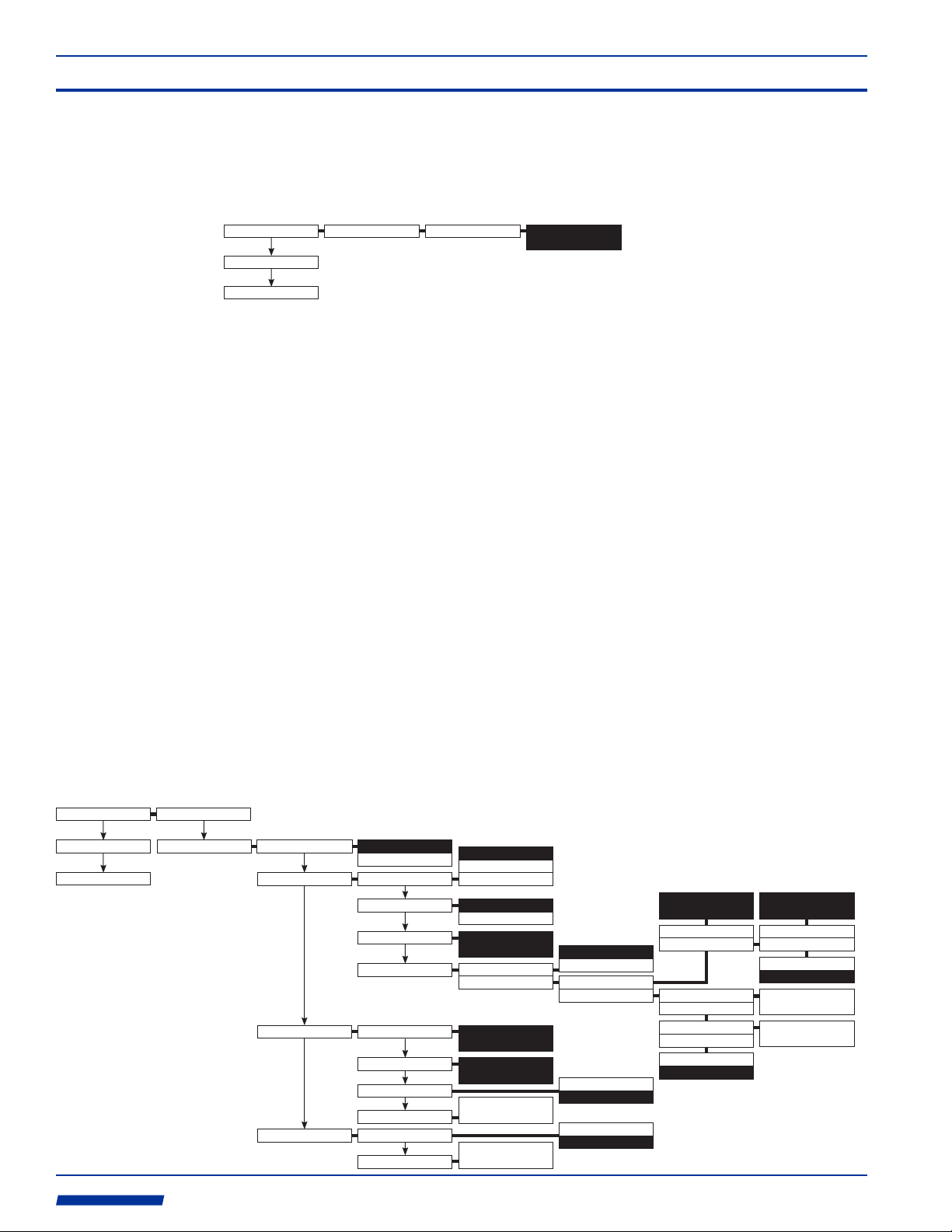
7.4 Menu Flow Chart
Configuration
Run
Save Config
Paddle Wheel
XDCR Settings
Meter Settings
K-Factor
Meas. Units
Enter Value
ENGLISH
METRIC
Transducer
Mount Method
Cable Length(ft)
Flow Direction
Pipe
Pipe Outside Dia.
Pipe Wall Thick.
Pipe Material
Pipe SOS
Fluid Fluid Type
Fluid SOS
Logging
Log Interval(s)
Rate Set Point 1
Rate Set Point 2
Tot. Set Point 1
Tot. Set Point 2
Tot. Set Point 3
Tot. Set Point 4
Tot. Set Point 5
Copy Logs
Delete Logs
Display
Flow Rate Volume Units
Model
0.0000
C
I
J
V
W
Enter Value
0.0000
Direction
Settings
Enter Value
0.0000
Enter Value
0.0000
Enter Value
0.0000
Enter Value
0.0000
Enter Value
0.0000
Enter Value
0.0000
Enter Value
0.0000
Enter Value
0.0000
Time Units
Fl. Rate Decimal
A -> B
B -> A
A -> B
B -> A
Enter Value
0.0000
Enter Value
0.0000
Enter Value
0.0000
Enter Value
0.0000
Seconds
Minutes
Hours
Days
Enter Value
Enter Value
0.0000
Scaling(A->B)
Zero(A->B)
Scaling(A->B)
Zero(A->B)
Zero Value(A->B)
Sign(A->B)
Positive
Negative
Custom
Water
U.S. Gallons
Ounces
U.S. Barrels Liq.
U.S. Barrels Oil
Cubic Feet
Acre Feet
Imperial Gallons
Cubic Meters
Liters
Milliliters
FR Custom V/Gal
0
Sonic-Pro
Enter Value
0.0000
Zero Value(A->B)
Sign(A->B)
Positive
Negative
Enter Value
0.0000
Enter Value
0.0000
Custom
HDPE
Enter Value
0
ProSeries
by Blue-White Ind.
Industries, Ltd.
Industries, Ltd.
Totalizer Volume Units
Fl. Total Decimal
Flow Average(s)
Enter Value
Enable Tot. Clear?
Yes
Low Fl. Cut-Off
High Fl. Cut-Off
Enter Value
Enter Value
Enter Value
0
No
0
U.S. Gallons
Ounces
U.S. Barrels Liq.
0
U.S. Barrels Oil
Cubic Feet
Acre Feet
Imperial Gallons
Cubic Meters
Liters
Milliliters
TOT Custom V/Gal
Enter Value
0
999
Scaling Off-set
Zero Off-set
SOS Fault Window
Enter Value
1.0000
FR Offset
Sign
Enter Value
Enter Value
0.0000
Positive
Negative
10
Sleep Time(s)
Enter Value
0
d
Page 31

Sonic-Pro
Page 30
Output Settings
Analog 4-20mA
Pulse 0-1000
Contact Closure
Clock CLOCK SET
Calibration
Clear Cal. Value
Global Config.
Save Conf. To USB
Restore USB Conf.
Firmware Update
Change Password
Anybus
2013/07/24
14:31
OK CANCEL
Calibration
Password
Rate at Min Curr.
Min Analog O/P
Rate at Max Curr.
Max Analog O/P
Rate at Min Freq.
Min Frequency
Rate at Max Freq.
Max Frequency
CALIBRATION
CANCEL
No
Yes
Enter Value
0
Save Conf. To USB
USB Drive Found!
Config. Copied To USB
OK
Restore USB Conf.
Config. File Found.
Erasing Config File..
Restored Config.
OK
Firmware Upgrade
USB Drive Found.
Press ESC to upgrade
OK
Change Password
Old Pass.:
NEW Pass.:
0000
0000
OK CANCEL
Relay A
Relay B
Enter Value
0.0000
Enter Value
4
Enter Value
0.0000
Enter Value
20
Enter Value
0.0000
Enter Value
0
Enter Value
0.0000
Enter Value
1000
None A
Monitor Flow Rate
Monitor Totalizer
Faults A
None B
Monitor Flow Rate
Monitor Totalizer
Faults B
Type
Address
High Trigger A
High Release A
Low Trigger A
Low Release A
Time(s) A
Batch Amt. A
Contact Timer(s) A
High Trigger B
High Release B
Low Trigger B
Low Release B
Time(s) B
Batch Amt. B
Contact Timer(s) B
Profibus DPV1
Modbus RTU
Modbus TCP
Ethernet
Profinet
None
Profibus DPV1
Modbus RTU
Modbus TCP
192.168.234.123
Ethernet
192.168.234.123
Profinet
None
192.168.234.123
Enter Value
0
Enter Value
0
Enter Value
0
Enter Value
0
Enter Value
0
Enter Value
0
Enter Value
0
Enter Value
0
Enter Value
0
Enter Value
0
Enter Value
0
Enter Value
0
Enter Value
0
Enter Value
0
Enter Value
0
Enter Value
0
IP SET
OK CANCEL
IP SET
OK CANCEL
IP SET
OK CANCEL
ProSeries
by Blue-White Ind.
Industries, Ltd.
Industries, Ltd.
d
Page 32

Limited Warranty
!
Blue-White Sonic-Pro flowmeters are warranted to be free from defects in material and workmanship for 24
months from date of factory shipment. WARRANTY COVERAGE IS LIMITED TO REPAIR OR REPLACEMENT
OF THE DEFECTIVE FLOWMETER ONLY. UNDER NO CIRCUMSTANCES SHALL BLUE-WHITE BE LIABLE
FOR ANY CONSEQUENTIAL OR INCIDENTAL LOSES OR DAMAGES THAT SHOULD ARISE FROM THE USE
OF THE FLOWMETER AND IN NO EVENT SHALL THE COMPANIES LIABILITY EXCEED THE PURCHASE
PRICE PAID BY THE PURCHASER FOR THE PRODUCT.
!
This warranty does not cover damage to the flowmeter that results from misuse or alterations, nor damage that
occurs as a result of improper installation.
!
Blue-White assumes no liability for the acceptability of the flowmeter in a specific application. THE USER MUST
DETERMINE THE ACCEPTABILITY OF THE PRODUCT AND ITS FITNESS FOR USE IN THE SPECIFIC
APPLICATION.
!
Flowmeters are repaired at the factory only. Call or write the factory to receive a RMA (return materials authorization) number. Carefully pack the flowmeter to be returned and write the RMA number on the outside of the shipping
carton. Include a brief description of the problem and the application.
!
Prepay all shipping costs. The factory does not accept C.O.D. Shipments. Damage that occurs during shipping is
the responsibility of the sender.
Users of electrical and electronic equipment (EEE) with the WEEE marking per Annex IV of the
WEEE Directive must not dispose of end of life EEE as unsorted municipal waste, but use the
collection framework available to them for the return, recycle, recovery of WEEE and minimize
any potential effects of EEE on the environment and human health due to the presence of
hazardous substances. The WEEE marking applies only to countries within the European Union
(EU) and Norway. Appliances are labeled in accordance with European Directive 2002/96/EC.
Contact your local waste recovery agency for a Designated Collection Facility in your area.
ProSeries
2
TWO-YEAR
WARRANTY
ProSeries
TM
by Blue-White Ind.
5300 Business Drive, Huntington Beach, CA 92649 USA
Phone: 714-893-8529 FAX: 714-894-9492
E mail: sales@blue-white.com or techsupport@blue-white.com URL: www.blue-white.com
P.N. 80000-493 DRAFT Rev. 06222014
 Loading...