


F-2000
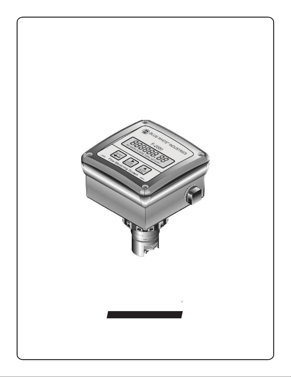
F-2000
MODEL PC - MODEL PB - MODEL AO
OUTPUT BOARDS
INSTRUCTION MANUAL
R
Blue-White
Industries, Ltd.
5300 Business Drive
Huntington Beach, CA 92649
USA
Phone: 714-893-8529 FAX: 714-894-9492
E mail: sales@blue-white.com or techsupport@blue-white.com
Website: www.blue-white.com
F-2000
1.0 F-2000 Electrical Wiring Connections
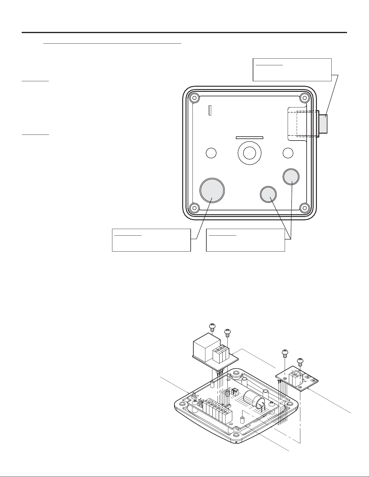
1.1Enclosure knock-out Instructions
Option A: Conduit Connection
1. Remove the red cap plug.
2. Install your pipe fitting (1/2 - 14 NPT male
end).
Page 2
Option A: 1 / 2-14 MPT
Red Cap Plug
(for pipe fitting)
Option B: Liquid-Tight Connections
Internal View
1. Remove knock-out(s) using a screwdriver.
2. Trim edge(s) with a knife and remove sharp
edges.
3. Install the provided liquid-tight connector(s).
Option B: 3/4 DIA.
Knock-out
(large liquid-tight connector)
Option B: 1/2 DIA.
Knock-out
(small liquid-tight connector)
Notes:
For the large liquid-tight connector (3/4” Knock-out), the acceptable cable diameter is between .200 - .394 in (5.1 -
10.0 mm).
For the small liquid-tight connector (½”Knock-out), the acceptable cable diameter is between .118 - .255 in (3.0 -
6.5 mm).
1.2Optional Circuit Board Installation
CAUTION: DISCONNECT POWER
SOURCE BEFORE SERVICING.
1. Carefully align optional board’s Pin
Header with the Pin Header socket
located on the main circuit board.
2. Press firmly into place.
3. Secure the board with the two screws
provided.
F-2000
Enclosure
Cover
(OPTIONAL BOARD)
N.C.
N.O.
C
F-2000-PC
F-2000-PB
(MAIN BOARD)
F-2000-RT
F-2000-AO
(OPTIONAL
BOARD)
Page 3
1.3Model RT Circuit Board Wiring
CAUTION: DISCONNECT POWER SOURCE BEFORE SERVICING.
Jumper Configuration
F-2000
Jumpers
J1 Installed
J1 Left Open
J2 Installed
J2 Left Open
J3 Installed and J4 Left Open
J3 Left Open and J4 Installed
Terminal Configuration
Terminal Function
Supply power
input
AC coil sensor
input
6
5
2
3
1
Hall Effect
sensor input
2
3
Open connector
pulse output
(from sensor)
7
4
Function
Battery Input (4 - 1.5 VDC, AA Cells)
Plug-In Transformer (115 VAC / 15 VDC, 220 VAC / 15 VDC, 230 VAC / 15 VDC)
Front Panel Programming is Disabled
Front Panel Programming is Enabled (factory default)
Hall Effect Sensor Input
AC Coil Sensor Input
Positive (+) power input (red wire from battery pack, or black with stripe wire from 15 VDC plug-in transformer)
Ground (-) power input (black wire from battery pack or 15 VDC plug-in transformer)
Ground (-) input (black wire from coil sensor body)
Pulse input (yellow or red wire from coil sensor body)
Positive (+) input (red wire from hall effect sensor)
Ground (-) input (black wire from hall effect sensor)
Pulse input (bare wire from hall effect sensor)
NPN positive (+) signal output
NPN negative (-) signal output
(Max voltage: 24VDC, Max load: 15mA, 2k ohm pull-up recommended.)
F-2000 RT Board
F-2000 PC Board
Mounting Screw
Bushings
SIP Socket for
F-2000 PC Board
Jumpers
BAT = ON
J1
J3
J2
PHM
Backup Battery
Connector
J4
7654321
SIP Socket for
F-2000 AO Board
F-2000 AO Board
Mounting Screw
Bushings
Terminal Blocks
Jumper Positions
Jumper Not
Installed (open)
Jumper
Installed
F-2000
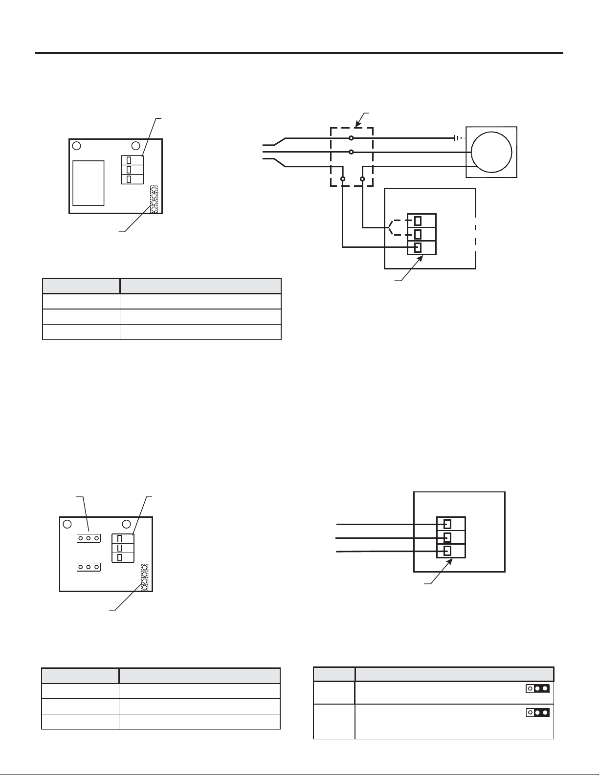
1.4Model PC Circuit Board Wiring
CAUTION: DISCONNECT POWER SOURCE BEFORE SERVICING.
Page 4
Terminal
Relay
Block
3
NC
2
NO
1
C
Earth Ground (green)
AC
Pin Header
(Other side)
Terminal Configuration
Terminal Terminal Block Connections
1
2
3
Output Type: Isolated relay SPDT (single poll double throw), NO / NC
Max. Load: 8 amps (AC) @ 115 VAC, 220 VAC, 230 VAC
Max. Voltage: 250 VAC, 125 VDC
Common
NO (Normally Open) contact
NC (Normally Closed) contact
7 amps (DC) @ 30 VDC (resistive load)
Common (-)
Hot (+)
Junction Box (not supplied)
Earth Ground (green)
Load Neutral (-)
Load Hot (+)
F-2000-PC Board
3-position
Terminal Block
External
Equipment
Load
(normally Closed Contact)
3
NC
(normally Open Contact)
NO
2
(common Contact)
1
C
1.5Model PB Circuit Board Wiring
CAUTION: DISCONNECT POWER SOURCE BEFORE SERVICING.
Jumpers
JP1
JP2
NC
IN
NO
EX
Pin Header
(Other side)
Terminal Configuration
Terminal Terminal Block Connections
1
2
3
Voltage input (+)
Switched output (NO/NC)
Ground (-)
3
2
1
Terminal
Block
G
OUT
V
Output Type: Non-Isolated contact closure switch, NO / NC
Max. Load: 100 milliamps (.10 amp)
Max. Voltage: 30 VDC if JP2 is set for external power.
15 VDC if JP2 is set for internal power and F-2000 is powered by plug-in transformer.
3 VDC if JP2 is set for internal power and F-2000 is powered by Batteries.
Max. Power: 3 Watts
Ground (-)
Switched Output (NO/NC)
Supply (+) (voltage input)
3-position
Terminal Block
Jumper Configuration
Jumper SettingsJumper
JP1
JP2
NC = Normally closed contacts
NO = Normally open contacts (default)
IN = Internal power
EX = External power (default)
Note: See above voltage limits
F-2000-PB Board
G
3
2
OUT
1
V
JP1
NC
NO
JP2
IN
EX
Page 5
1.6Model AO Circuit Board Wiring
CAUTION: DISCONNECT POWER SOURCE BEFORE SERVICING.
Jumper Configuration
Output Jumper Settings
Connect P1 & P2 (leave P3 open) (factory
4-20 Milliamp
0-10 Volts DC
Terminal Configuration
Terminal Number Terminal Block Connections
default), Max Load = 250 Ohms
Connect P2 & P3 (leave P1 open), Max Load =
500 Ohms
P2
P3P1
P2
P3P1
Pin Header
(other side)
A
-
P2
21
F-2000
3 position
jumper Pin
P3P1
V
+
1
2
Output Type: Linear, Non-Isolated, powered loop.
Loop resistance: 250 ohm maximum for 4-20mA output
Positive (+) Analog Output Signal
Negative (-) Analog Output Signal
500 ohm maximum for 0-10 V DC
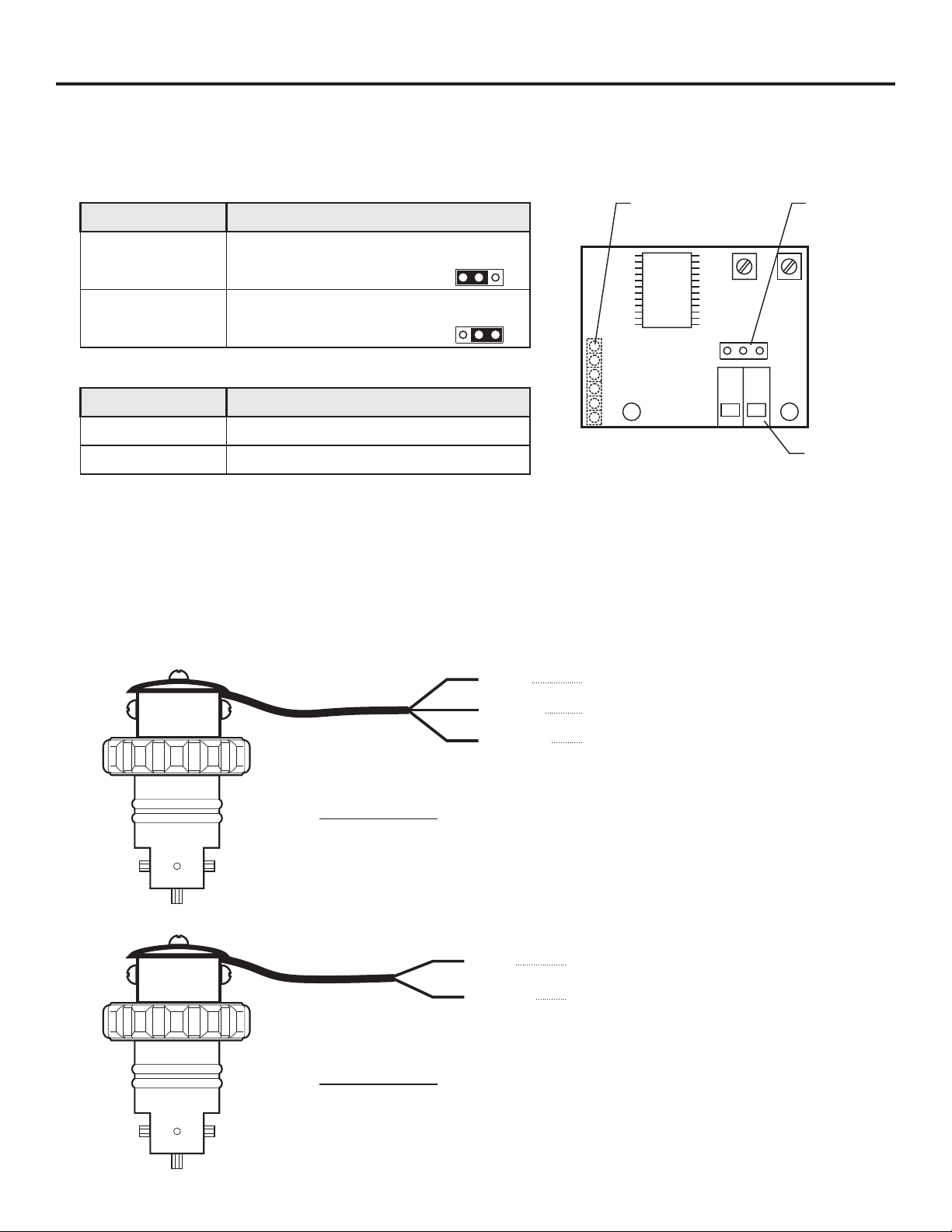
1.7Model FHXX and FCXX Sensor wiring
Model FHXX
Note: Output type - current sinking type hall effect sensor (13.5mA max).
Pull-up resistor is recommended. 5k ohm across red & bare wires.
RED
BARE
BLACK
Terminal
Block
Input Supply Voltage (+ 6 to 24 Vdc)
Signal Output (square wave)
Ground (-)
Model FCXX
RED
BLACK
Signal Output (Sine wave)
Ground (-)

F-2000
2.0 HOW TO OPERATE THE MODEL PC and MODEL PB
2.1What Was The MODEL PC and PB Designed To Do?
In addition to the features of the MODEL RT, the model PC includes a single SPDT relay which can be used to
switch an external component such as a pump, valve, alarm buzzer, etc., on and off in order to assist in the
control of a process. The relay setpoints must be assigned to either the rate mode, the batch (total) mode, or
turned off. The MODEL PC cannot be battery operated.
The MODEL PB offers all of the features of the MODEL PC but includes a contact closure switch instead of a
relay and may be battery operated.
!
High level flow rate alarm.
!
Low level flow rate alarm.
!
High and low level flow “range” alarm.
!
Manual start or automatically timed start batch processing.
!
Proportional chemical feed injector pump control.
2.2What Features Are Available?
!
All controls are front panel programmable.
!
MODEL PC Max. switching load 8 Amp at - 115 VAC, 230 VAC, 220 VAC; 7 Amp at 30 VDC (resistive load).
!
MODEL PB Max. switching load 100 milliamp at 30 VDC.
!
NO / NC contact.
!
Rate alarms can be latched requiring a manual reset.
!
Programmable “alarm release value” provides hysteresis to prevent relay flickering (see page 28).
!
High and low range alarms can be independently programmed.
!
Alarm delay timer temporarily silences alarms for a programmed time from 0-999 seconds.
!
Independent display and resetting of batch count and batch amount.
!
Front panel clearing of batch counts and amounts can be disabled.
!
Turn on / off external devices, for a programmable time from 0-999 seconds per batch.
Page 6
2.3How Do I Program The MODEL PC & PB?
The Model PC & PB setpoints must be assigned to either the rate mode (option 1), the batch (total) mode
(option 2), or turned off (option 3).
Option 1 - Assign the setpoints to the RATE mode for applications involving the switching of external devices,
such as alarms or valves, when the rate of flow is greater than or less than the programmed flow
RATE value. The Model PC and PB is used to monitor flow RATE in this mode. Example: High or
low flow rate alarms.
Option 2 - Assign the setpoints to the BATCH mode for applications involving the switching of external devices
such as chemical metering pumps, centrifical pumps, solenoid valves, etc., when the amount of flow
is greater than or less than the programmed batch amount value. In this mode, the Model PC is used
to monitor flow total. Example: Manual batch processing or proportional feed rate control.
Option 3 - The OFF mode opens the relay contacts regardless of the flow conditions. The setpoints are not
assigned.
SETPOINT MODE SELECTION PROGRAMMING SCREEN OPTIONS
OPTION
Option - 1 (page 27)
Option - 2 (page 32)
Option - 3
SELECTION FUNCTION
Setpoint - RATE Relay Setpoints are assigned to flow RATE mode.
Setpoint - BATCH Relay Setpoints are assigned to BATCH (accumulative or “total”) mode.
Setpoint - OFF Relay Setpoints are not assigned. Relay is not energized.
 Loading...