

Page 1
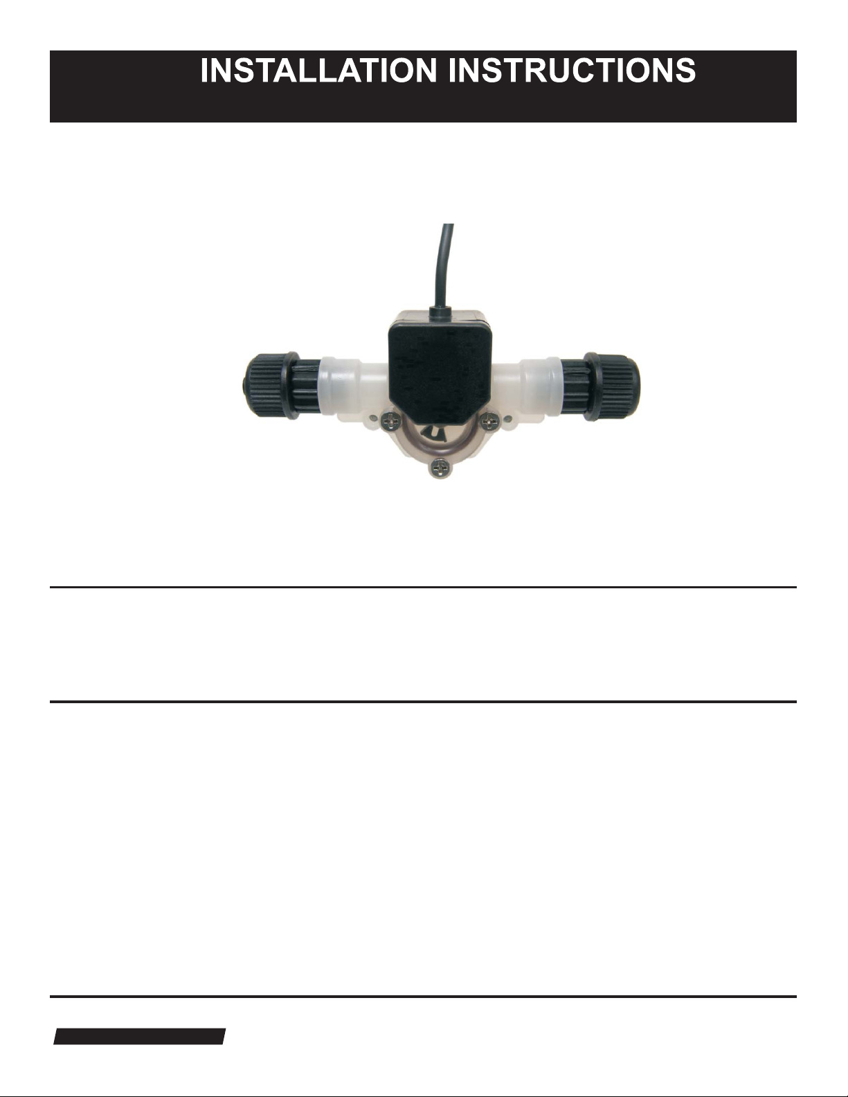
Micro Flow - FVS (Flow Verification Sensor)
Electronic Flow Verification
Are you sure the pump is actually pumping?
Empty chemical tank, clogged injection fitting, lost prime, an other problems can prevent a metering pump from
actually injecting chemical - even though the pump is in good working order.
Installation Options
The Micro Flow FVS (Flow Verification Sensor) is designed to give you many installation options.
The sensor can be installed:
!
Directly on the pumphead of a Blue-White pump (see next page).
!
Anywhere on the discharge side of a diaphragm pump.
!
Anywhere on the suction side of a peristaltic pump.
The wiring for the sensor can be connected directly to a Blue-White pump. The pump will stop pumping if the
sensor detects no flow. A relay will then close allowing for remote alarm indication or initiation of a back-up
injector pump.
®
80000-402 02/28/2008
Blue-White
Industries, Ltd.
Industries, Ltd.
5300 Business Drive | Huntington Beach | CA | 92649 | USA
Page 2
FVS
Installation Guideline
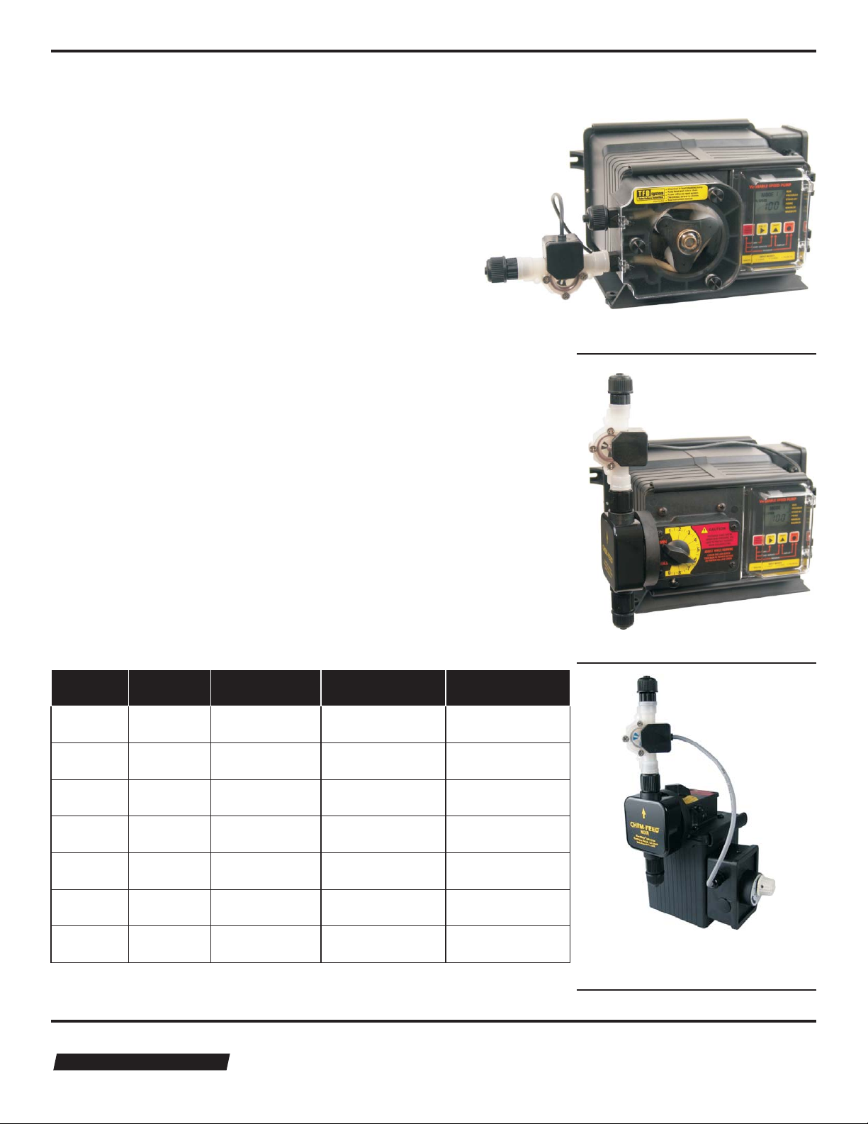
The Micro Flow FVS can be connected directly to many
Blue-White injector pumps (see table below). The sensor
will verify that chemical injection has actually occurred.
The pumps sophisticated electronics continuously monitor
the sensor. If chemical should fail to inject, the pump will
stop and an alarm relay will close - allowing for remote
alarm indication and/or initiation of a back-up injector
pump.
Recommended sensor mounting locations differ from
diaphragm pump to peristaltic pump.
Diaphragm pump installation; the sensor should be
mounted on the discharge (outlet) side of the pumphead.
The sensor can be mounted directly on the pumphead or
anywhere along the tubing on the discharge side of the
pump.
Page 1
A-100NV
Peristaltic Pump
Peristaltic pump installation; the sensor should be
mounted on the suction (inlet) side of the pumphead.
Blue-White FVS compatible metering pumps:
Pump
Series
A-100NV
A-100NA
A-100NF
C-1100V
C-1100A
C-1100F
C-1500NK
Pump Type FVS Installation
Peristaltic Suction side of
Peristaltic Suction side of
Peristaltic Suction side of
Diaphragm Discharge side of
Diaphragm Discharge side of
Diaphragm Discharge side of
Diaphragm Discharge side of
Pump
Description
Variable speed
Fixed speed
timer controlled
Fixed speed
timer controlled
Variable speed
Fixed speed
timer controlled
Fixed speed
timer controlled
Fixed speed
timer controlled
Pump ShutDown Time*
User programmable
(up to 256 seconds)
6 seconds
6 seconds
User programmable
(up to 256 seconds)
6 seconds
6 seconds
6 seconds
Location
pump head
pump head
pump head
pump head
pump head
pump head
pump head
* Pump Shut-Down Time = If chemical should fail to inject in the amount
of time specified, the pump will automatically shut-down, also triggering
an alarm relay.
®
Blue-White
Industries, Ltd.
Industries, Ltd.
C-1100V
Diaphragm Pump
C-1500NK
Diaphragm Pump
Page 3

FVS
Page 2
Your flow verification sensorpackage includes a Foot Strainer (see diagram below). This strainer will prevent any small
particles from entering and clogging the Micro Body. Diaphragm pumps will require a strainer and a check valve. The part
number for the strainer that includes a check valve is C-340A. Blue-White peristaltic pumps do not require a check valve.
Suction Tubing
Foot Strainer
Part Number
C-340X
Red
+
Wiring Diagram
8 to 28 Vdc (Positive)
Strainer Adapter
Strainer Body
Screen Strainer
Exploded View
+5v dc
0v dc
Sensor
Body
Size
Flow Range
(ml/min)
30-3001
100-10002
200-20003
300-30004
500-50005
700-70006
Bare
Black
+ 5 Vdc (signal output)
_
(Ground)
Sensor connections:
Input voltage (vdc) 8 to 28 vdc
Output voltage (v) “high state” 4 80 v dc min (5 vdc normal)
Output voltage (v) “low state” 0 2v dc max
(True digital Square-wave output)
K-Factors (pulses per fluid volume)
Pulses per
Gallon
181,336
81,509
42,051
25,153
15,737
9,375
Pulses per
Liter
47,909
21,535
13,752
6,646
4,157
2,477
Useful formulas
60 / K = rate scale factor
rate scale factor x Hz = flow rate in volume per minute
1 / K = total scale factor
total scale factor x n pulses = total volume
Blue-White
Industries, Ltd.
Industries, Ltd.
®
Page 4

FVS
Page 3
Temperature vs. Pressure
Temperature
200°F / 93.3°C
190°F / 87.8°C
180°F / 82.2°C
170°F / 76.7°C
160°F / 71.1°C
150°F / 65.6°C
140°F / 60°C
130°F / 54.4°C
120°F / 48.9°C
110°F / 43.3°C
100°F / 37.8°C
90°F / 32.2°C
80°F / 26.7°C
70°F / 21.1°C
0 / 0
PVDF
PVC
25 / 1.7
50 / 3.4
Pressure Temperature and
75 / 5.2
PSIg / BAR
100 / 6.9
130 / 9
150 / 10.3
Pressure and temperature limits are inversely proportional. At the maximum suggested pressure the temperature should approach 70°F / 21.1°C. At the maximum suggested temperature the pressure should approach
zero psi. We cannot guarantee our flowmeters will not be damaged either at or below the suggested limits
simply because of many factors which influence meter integrity; stress resulting from meter misalignment,
damage due to excessive vibration and/or deterioration caused by contact with certain chemicals as well as
direct sunlight. These situations and others tend to reduce the strength of the materials from which the meters
are manufactured.
Application Note
Although meters may be suitable for other chemicals, Blue-White cannot guarantee their suitability. It
is the responsibility of the user to determine the suitability of the flowmeter in their application.
Blue-White
Industries, Ltd.
Industries, Ltd.
®
Page 5

FVS
Page 4
Exploded View and Parts List
6
7
6
1
2
12
10
9
8
11
3
4
5
Item Description Catalog number Quantity
1. Micro-Body .031 30-300ml/min 90002-226 1
.062 100-1000ml/min 76001-301
.093 200-2000ml/min 76001-302
.125 300-3000ml/min 76001-303
.156 500-5000ml/min 76001-304
.187 700-7000ml/min 76001-305
2. Tubing, PVC 76001-299 2
3. O-Ring, Viton 90003-012 2
4. Adapter, PVDF 90002-038 2
. (Optional Threaded Fitting PVC)
5. Tube Nut 90002-047 2
6. Sensor Assembly 90010-252 1
7. Screws, SS 90011-113 4
8. Screws, SS 90011-081 4
9. Lens Cap, PVC (Optional PVDF) 90002-227 1
10. Axel, PVDF 90007-592 1
11. Paddle, PVDF 90002-230 1
12. O-Rng, Viton 90003-143 1
NOTE: The “Exploded View” drawing illustrates assembly of the FVS (Flow Verification Sensor) If your
FVS needs to be cleaned refer to this drawing when reassembling the unit.
®
Blue-White
Industries, Ltd.
Industries, Ltd.
Page 6

Blue-white Industries
Limited Warranty
FVS Sensors are warranted to be free of defects in material and workmanship for up to 12 months from the
date of factory shipment. Warranty coverage is limited to repair or replacement of the defective flowmeter only.
Blue-White Industries does not assume responsibility for any other damage that may occur.
This warranty does not cover damage to the FVS sensors that results from misuse or alterations, nor damage
that occurs as a result of: meter misalignment, improper installation, over tightening, use of non- recommended
chemicals, use of non-reccomended adhesives or pipe dopes, excessive heat or pressure, or allowing the
meter to support the weight of related piping. FVS Sensors are tested and calibrated with water and air only.
Although meters may be suitable for other chemicals, Blue-White cannot guarantee their suitability.
FVS Sensors are repaired at the factory only. Call or write the factory to receive a Return Authorization
Number, carefully pack the FVS to be returned, including a brief description of the problem. Note the RA
number on the outside of the carton.
Prepay all shipping costs. The factory does not accept COD Shipments. Damage that occurs during shipping is
the responsibility of the sender.
BLUE-WHITE INDUSTRIES
5300 Business Drive, Huntington Beach, CA 92649
(714) 893-8529 • FAX (714) 894-9492
URL: www.Blue-White.com
E-mail: sales@blue-white.com Phone: 714-893-8529
Techsupport@blue-white.com Fax: 714-894-0149
Blue-White
Industries, Ltd.
®
Users of electrical and electronic equipment (EEE) with the WEEE marking per Annex IV of
the WEEE Directive must not dispose of end of life EEE as unsorted municipal waste, but
use the collection framework available to them for the return, recycle, recovery of WEEE
and minimize any potential effects of EEE on the environment and human health due to the
presence of hazardous substances. The WEEE marking applies only to countries within the
European Union (EU) and Norway. Appliances are labeled in accordance with European
Directive 2002/96/EC.
Contact your local waste recovery agency for a Designated Collection Facility in your area.
80000-402 02/28/2008
 Loading...