

Page 1
5300 Business Drive, Huntington Beach, CA 92649 USA
Phone: 714-893-8529 FAX: 714-894-9492
E mail: sales@blue-white.com or techsupport@blue-white.com URL: www.blue-white.com
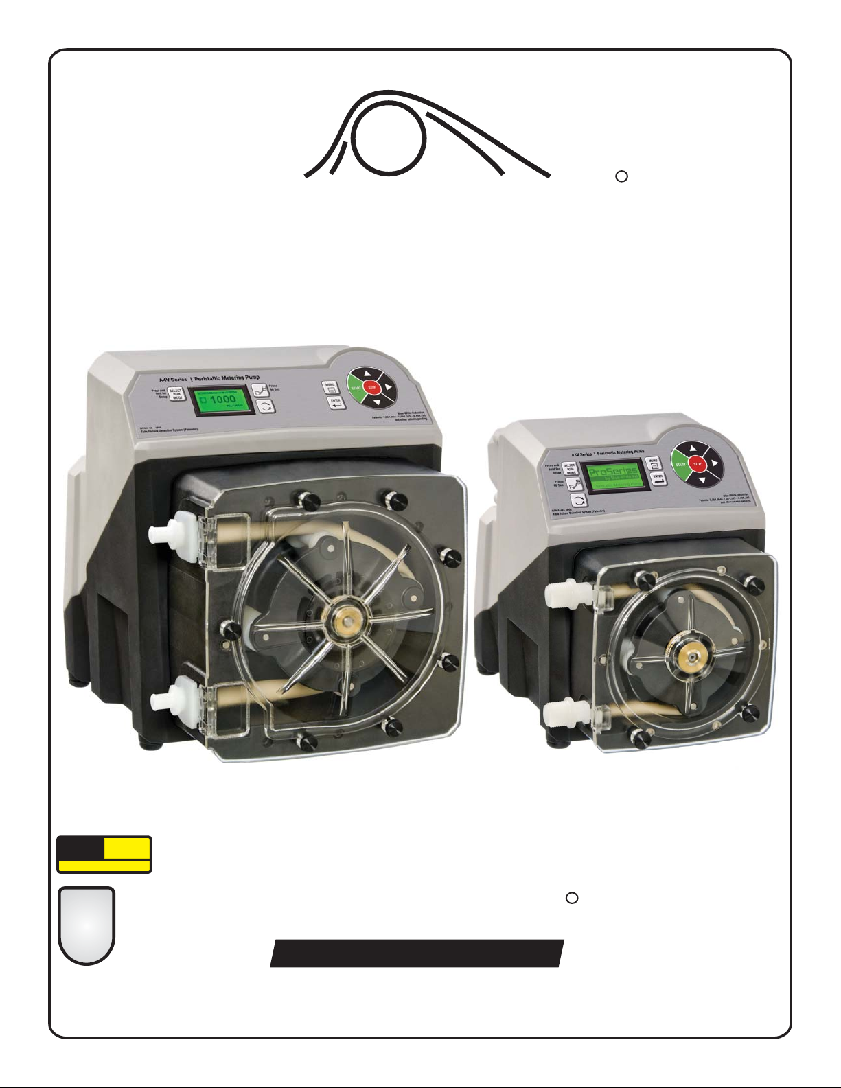
SERIES A3V and A4V
Operating Manual
ProSeries
by Blue-White Ind.
TM
FLEX-PRO
Peristaltic Metering Pump
system
TFD
Tube Failure Detection
Exclusive:
2
TWO-YEAR
WARRANTY
ProSeries
R
R
Protected by Patents: 7,001,153;
7,284,964; 4,496,295
and other patents pending
Patent No. 7,001,153 & 7,284,964
CERTIFIED FINAL DOCUMENT
Page 2

Page 2
Flex-Pro
TABLE OF CONTENTS
Section Heading Page
1.0 Introduction . . . . . . . . . . . . . . . . . . . . . . . . . . . . . . . . . . . . . . 2
1.1 Available Models . . . . . . . . . . . . . . . . . . . . . . . . . . . . . . . . ...3
1.2 Specifications . . . . . . . . . . . . . . . . . . . . . . . . . . . . . . . . . . . . . 4
1.3 Materials of Construction . . . . . . . . . . . . . . . . . . . . . . . . . . . . . 4
1.4 Features . . . . . . . . . . . . . . . . . . . . . . . . . . . . . . . . . . . . . . . . . 5
1.5 Agency Listings . . . . . . . . . . . . . . . . . . . . . . . . . . . . . . . . . . . . 5
2.0 Installation . . . . . . . . . . . . . . . . . . . . . . . . . . . . . . . . . . . . . . . 6
2.1 Mounting Location . . . . . . . . . . . . . . . . . . . . . . . . . . . . . . . . . . 6
2.2 Mounting Dimensions. . . . . . . . . . . . . . . . . . . . . . . . . . . . . . . . 6
2.3
2.4 Input Power Connections . . . . . . . . . . . . . . . . . . . . . . . . . . ...8
2.5 Wiring Terminals and I/O Schematics . . . . . . . . . . . . . . . . . . . . 9
3.0 How to Operate Flex-Pro. . . . . . . . . . . . . . . . . . . . . . . . . . . . 10
3.1 Menu Navigation . . . . . . . . . . . . . . . . . . . . . . . . . . . . . . . . . . . 11
3.2 Configuration Menu . . . . . . . . . . . . . . . . . . . . . . . . . . . . . . . . . 12
3.2.1 Language Selection . . . . . . . . . . . . . . . . . . . . . . . . . . . . . . . . . 12
3.2.2 Display Rate (units of measure) . . . . . . . . . . . . . . . . . . . . . . . . 13
3.2.3 Reset Factory Defaults. . . . . . . . . . . . . . . . . . . . . . . . . . . . . . . 13
4.0 Input Setup. . . . . . . . . . . . . . . . . . . . . . . . . . . . . . . . . . . . . . . 14
4.1 Max RPM cut-off . . . . . . . . . . . . . . . . . . . . . . . . . . . . . . . . . . . 15
4.2 Max Flowrate (Output Calibration) . . . . . . . . . . . . . . . . . . . . . . 15
4.3 Input Setup (Operating Mode Configuration) . . . . . . . . . . . . . . . 16
4.3.1 Manual Adjust (manual speed adjust) . . . . . . . . . . . . . . . . . ...16
4.3.2 4 - 20 mA Input . . . . . . . . . . . . . . . . . . . . . . . . . . . . . . . . . . . . 17
4.3.3 0 - 10 VDC Input . . . . . . . . . . . . . . . . . . . . . . . . . . . . . . . . . . . 18
4.3.4 Frequency Input (Hz) . . . . . . . . . . . . . . . . . . . . . . . . . . . . . . . . 19
4.3.5 Pulse Batch (low speed batch) . . . . . . . . . . . . . . . . . . . . . . . . . 20
4.3.6 Manual Cycle Adjust (repeating cycle timer). . . . . . . . . . . . . . . .21
4.3.7 Dispensing . . . . . . . . . . . . . . . . . . . . . . . . . . . . . . . . . . . . . . . 22
4.3.8 Manual Dosing . . . . . . . . . . . . . . . . . . . . . . . . . . . . . . . . . . . . 23
4.3.9 Proportional Dosing . . . . . . . . . . . . . . . . . . . . . . . . . . . . . . . . . 24
4.4 Contact Closure Input (Remote start/stop) . . . . . . . . . . . . . . . . . 25
4.5 Set FVS (Flow Verification System). . . . . . . . . . . . . . . . . . . ...26
4.6 TFD (Tube Failure Detection) . . . . . . . . . . . . . . . . . . . . . . . . . . 27
4.6.1 TFD Adjustment. . . . . . . . . . . . . . . . . . . . . . . . . . . . . . . . . . . . 27
4.7 Remote/Local Control. . . . . . . . . . . . . . . . . . . . . . . . . . . . . . . . 28
4.8 Pump Tube Timer . . . . . . . . . . . . . . . . . . . . . . . . . . . . . . . . . . 28
5.0 Output Setup (Alarm Relays & Output Signal signals) . . . . . . 29
5.1 Signal Output . . . . . . . . . . . . . . . . . . . . . . . . . . . . . . . . . . . . . 30
6.0 Pump Maintenance. . . . . . . . . . . . . . . . . . . . . . . . . . . . . . . . . 31
6.1 Routine Inspection and Maintenance. . . . . . . . . . . . . . . . . . . . . 31
6.2 How to Clean and Lubricate the Pump . . . . . . . . . . . . . . . . . . . 31
6.3 Reverse Rotor Rotation . . . . . . . . . . . . . . . . . . . . . . . . . . . . . . 31
6.4 Tube Replacement. . . . . . . . . . . . . . . . . . . . . . . . . . . . . . . . . . 32
6.5 A3 Replacement Parts List . . . . . . . . . . . . . . . . . . . . . . . . . . . . 34
6.6 A4 Replacement Parts List . . . . . . . . . . . . . . . . . . . . . . . . . . . . 34
7.0 Tubing Data . . . . . . . . . . . . . . . . . . . . . . . . . . . . . . . . . . . . . . 36
7.1 Tube Life Estimates . . . . . . . . . . . . . . . . . . . . . . . . . . . . . . . . . 36
7.2 Output Versus Fluid Viscosity . . . . . . . . . . . . . . . . . . . . . . . . . . 38
Installing Injection Fitting and Strainer . . . . . . . . . . . . . . . . . . . . 7
1.0 Introduction
Congratulations on purchasing the Flex-Pro variable speed Peristaltic Metering Pump.
Your Flex-Pro pump is pre-configured for the tubing that shipped with your metering pump. The tubing assembly
has an Identification number printed for easy re-order.
Please Note: Your new pump has been pressure tested at the factory with clean water before shipping. You may
notice trace amounts of clean water in the pre-installed tube assembly. This is part of our stringent quality assurance program at Blue-White Industries.
Page 3
Page 3
1.1 Available Models
Flex-Pro
* Inlet/outlet connection type
S = 3/8” OD x 1/4” ID tubing compressions type connections
M = 1/2”male NPT
B = 1/2” ID tubing barb type connections (available on A4 models only)
C-= 3/4” tri-clamp connections
! The Flex-Pro Peristaltic Pump’s motor speed is linear over the entire 0.05% to 100% adjustment
range.
! Output versus pressure is nearly linear in all models. Larger tubes exhibit greater losses.
! Output versus viscosity curves are shown at the end of this manual.
! For optimum tube life, specify the pump so that it operates at the lowest possible RPM and
pressure.
®
Tygothane A3 Tube Pumps
Meets FDA criteria for food | Resistant to oils, greases and fuels
GPH
.002 - 4.6
.004 - 10.1
.010 - 24.9
.011 - 28.5
LPH
.007 - 17.4
.015 - 38.4
.038 - 94.2
.043 - 108.0
ML/Min
.1 - 290
.3 - 637
.6 - 1570
.7 - 1800
RPM
125
125
125
125
115V AC
A3V24-*GE
A3V24-*GG
A3V24-*GH
A3V24-*GK
230V AC
A3V25-*GE
A3V25-*GG
A3V25-*GH
A3V25-*GK
220V AC
A3V26-*GE
A3V26-*GG
A3V26-*GH
A3V26-*GK
®
Norprene Chemical A3 Tube Pumps
Meets FDA criteria for food | Superior chemical resistance
LPH
.022 - 55.1
.043 - 108.0
230V AC
A3V25-*TH
A3V25-*TK
115V AC
A3V24-*TH
A3V24-*TK
GPH
.006 - 14.5
.011 - 28.5
220V AC
A3V26-*TH
A3V26-*TK
ML/Min
.4 - 920
.7 - 1800
RPM
125
125
®
Norprene A3 Tube Pumps
Meets FDA criteria for food | Excellent chemical resistance | CIP | SIP
LPH
.026 - 66.0
.038 - 96.0
.050 - 126
.003 - 7.8
230V AC
A3V25-*ND
A3V25-*NH
A3V25-*NK
A3V25-*NJ
115V AC
A3V24-*ND
A3V24-*NH
A3V24-*NK
A3V24-*NJ
GPH
.007 - 17.4
.010 - 25.3
.013 - 33.3
.001 - 2.10
220V AC
A3V26-*ND
A3V26-*NH
A3V26-*NK
A3V26-*NJ
ML/Min
.
.4 - 1097
.6 - 1596
.8 - 2100
05 - 132
Feed Rate
RPM
125
125
125
125
Max
Speed
A3 Model Numbers
PSI (bar)
65 ( )
65 ( )
65 ( )
4.5
4.5
4.5
65 (4.5)
Max
Pressure
PSI (bar)
125 (8.6)
125 (8.6)
125 (8.6)
125 (8.6)
PSI (bar)
50 (3.4)
50 (3.4)
LPH
.04 - 108
.07 - 168
.08 - 192
.09 - 204
.15 - 378
.24 - 600
230V AC
A4V25-*NH
A4V25-*NJ
A4V25-*NL
A4V25-*NP
A4V25-*NK
A4V25-*NHH
115V AC
A4V24-*NH
A4V24-*NJ
A4V24-*NL
A4V24-*NP
A4V24-*NK
A4V24-*NHH
220V AC
A4V26-*NH
A4V26-*NJ
A4V26-*NL
A4V26-*NP
A4V26-*NK
A4V26-*NHH
ML/Min
.7 - 1800
1.1 - 2800
1.3 - 3200
1.4 - 3400
2.5 - 6300
4.0 - 10000
RPM
125
125
125
125
125
125
PSI (bar)
125 (8.6)
100 (6.9)
80 (5.5)
50 (3.4)
30 (2.0)
100 (6.9)
Max
Temperature
F (C)
185 (85)
185 (85)
185 (85)
185 (85)
F (C)
130 (54)
130 (54)
F (C)
130 (54)
130 (54)
130 (54)
130 (54)
F (C)
185 (85)
185 (85)
185 (85)
185 (85)
185 (85)
185 (85)
®
Norprene A3 Tube Pumps
Meets FDA criteria for food | Excellent chemical resistance | Extra long life at low pressures
LPH
.050 - 126
230V AC
A3V25-*NKL
115V AC
A3V24-*NKL
GPH
.013 - 33.3
220V AC
A3V26-*NKL
ML/Min
.8 - 2100
RPM
125
PSI (bar)
30 (2.1)
F (C)
185 (85)
®
Tygothane A4 Tube Pumps
Meets FDA criteria for food | Resistant to oils, greases and fuels
GPH
.01 - 39.6
.02 - 55.5
.04 - 100
LPH
.06 - 150
.09 - 210
.20 - 378
ML/Min
1.0 - 2500
1.4 - 3500
2.5 - 6300
RPM
125
125
125
115V AC
A4V24-*GH
A4V24-*GK
A4V24-*GKK
230V AC
A4V25-*GH
A4V25-*GK
A4V25-*GKK
220V AC
A4V26-*GH
A4V26-*GK
A4V26-*GKK
®
Norprene Chemical A4 Tube Pumps
Meets FDA criteria for food | Superior chemical resistance
LPH
.03 - 78
.06 - 162
.08 - 192
230V AC
A4V25-*TH
A4V25-*TK
A4V25-*THH
115V AC
A4V24-*TH
A4V24-*TK
A4V24-*THH
GPH
.01 - 20.6
.02 - 42.8
.02 - 50.7
220V AC
A4V26-*TH
A4V26-*TK
A4V26-*THH
ML/Min
.5 - 1300
1.1 - 2700
1.3 - 3200
RPM
125
125
125
®
Norprene A4 Tube Pumps
Meets FDA criteria for food | Excellent chemical resistance | CIP | SIP
Feed Rate
Max
Speed
A4 Model Numbers
PSI (bar)
65 ( )
65 ( )
4.5
4.5
65 (4.5)
Max
Pressure
PSI (bar)
30 (2.1)
30 (2.1)
30 (2.1)
Max
Temperature
F (C)
130 (54)
130 (54)
130 (54)
F (C)
130 (54)
130 (54)
130 (54)
®
Norprene A4 Low Pressure Tube Pumps
Meets FDA criteria for food | Excellent chemical resistance | Extra long life at low pressures
LPH
.07 - 192
.17 - 420
230V AC
A4V25-*NKL
A4V25-*NKKL
115V AC
A4V24-*NKL
A4V24-*NKKL
GPH
.02 - 50.7
.04 - 111
220V AC
A4V26-*NKL
A4V26-*NKKL
ML/Min
1.3 - 3200
2.8 - 7000
RPM
125
125
PSI (bar)
30 (2.1)
30 (2.1)
F (C)
185 (85)
185 (85)
GPH
.01 - 28.5
.02 - 44.4
.02 - 50.7
.02 - 54.0
.04 - 100.0
.06 - 158.5
Page 4

Page 4
1.2 Specifications
Maximum working pressure (excluding pump tubes):
125 psig (8.6 bar)
Note: see individual pump tube assembly maximum pressure ratings.
Maximum Fluid temperature (excluding pump tubes):
oo
3/8” OD x 1/4” ID tubing connections: 130 F (54 C)
oo
M/NPT connections: 185 F (85 C)
Note: see individual pump tube assembly maximum temperature ratings.
Ambient Operating Temperature
OOOO
14 F to 115 F (-10 C to 46 C)
Ambient Storage Temperature
OOOO
-40 F to 158 F (-40 C to 70 C)
Operating Voltage:
A3 MODELS: 96 to 264VAC-50/60Hz, 220W
A4 MODELS: 96 to 264VAC-50/60Hz, 350W
Power Cord Options:
115V60Hz = NEMA 5/15 (USA)
230V60Hz = NEMA 6/15 (USA)
220V50Hz = CEE 7/VII (EU)
240V50Hz = AS 3112 (Australia/New Zealand)
Enclosure:
NEMA 4X (IP66), Polyester powder coated aluminum.
Maximum Overall Dimensions:
A3 models: 8-1/8”W x 10-3/4”H x 15-1/4”D (20.6W x 27.3H x 38.9D cm)
A4 models: 12-1/8”W x 14-1/4”H x 18-5/8”D (30.8W x 36.1H x 47.3D cm)
Approximate shipping wt:
A3 models: 33 lb. (15.0 Kg)
A4 models: 58 lb. (26.3 Kg)
Motor speed adjustment range 2,500:1:
0.05% - 100% motor speed
Motor speed adjustment resolution:
Maximum viscosity:
12,000 Centipoise
Maximum suction lift:
30 ft. Water, 0 psig (4.5 m, 0 bar)
Display
3 color VGA backlit LCD, UV resistant.
Display Languages
English, Spanish, French or German selectable.
Keypad
Ten button positive action tactile switch keypad.
Security
Programmable 4-digit password.
0.1% increments > 10% motor speed
0.01% increments > 1% motor speed and < 10%
0.001% increments < 1% motor speed
Wetted components:
Non-Wetted components:
Pump Tube Assembly (Model Specific - 2 provided):
q q q
Tubing: .....Norprene or Norprene Chemical or Tygothane
Adapter fittings: .PVDF
Enclosure:
413 Aluminum (Polyester powder coated)
Pump Head:
q
Valox (PBT) thermoplastic
Pump Head Cover:
Clear Acrylic - Annealed for added strength and chemical resistance.
Permanently lubricated sealed motor shaft support ball bearing.
Brass shaft support bearing retainer.
Cover Screws:
Stainless Steel
Roller Assembly:
q
Rotor:.................. ................Valox (PBT)
Rollers: ...............................Nylon
Roller Bearings: . ................SS Ball Bearings
Motor Shaft:
Chrome plated steel
TFD System Sensor pins:
Hastelloy C-276
Power Cord:
3 conductor, SJTW-A Water-resistant
Tube Installation Tool:
GF Nylon
Mounting Brackets and Hardware:
316 Stainless Steel
Injection / Back-flow Check valve:
Body & insert: . . . . . . PVDF
Check Ball: . . . . . . . . Ceramic
Spring: ..... .....Hastelloy C-276
q
Ball Seat O-ring: . . . . . Viton (optional EP)
q
Static Seal O-ring: . . . . Viton (optional EP)
q
Duckbill anti-scale valve: Santoprene
Ancillary Items provided
With “S” tubing type connections only:
Suction Tubing: . . . . . 3/8” OD x 1/4” ID x 10’ Clear PVC
Discharge Tubing: . . . . 3/8” OD x 1/4” ID x 10’ Polyethylene (LLDPE)
Suction Strainer: . . . . . Polypropylene
With “B” tubing and “M” M/NPT connections only:
Suction Strainer:
Body: .................PVDF
Check Ball: ............Ceramic
q
Ball Seat O-ring: ........Viton (optional EP)
1.3 Materials of construction
Flex-Pro
With “C” Tri-clamp connections only:
none
Page 5
1.4 Features
Enclosure Rating:
NEMA 4X: Constructed for either indoor or outdoor use to provide a degree of protection to personnel against
incidental contact with enclosed equipment; to provide a degree of protection against falling dirt, rain, sleet, snow,
windblown dust, splashing water, and hose-directed water; and that will be undamaged by external formation of ice
on enclosure.
IP66: No ingress of dust; complete protection against contact. Water projected in powerful jets against enclosure from
any direction shall have no harmful effects.
Page 5
!
!
!
!
!
!
!
!
!
!
!
!
Peristaltic pump design does not have valves that can clog requiring maintenance.
Self priming - even against maximum line pressure. By-pass valves are not required. Cannot vapor lock or
lose prime. Syphoning cannot occur.
2500:1 turndown ratio.
SCADA Inputs include: 4-20mA, 0-10Vdc, and Pulse inputs for remote external speed control and 0-30 VDC /
contact closure remote start/stop.
Operator friendly digital touch pad with menu driven software.
VGA Graphic multi-color backlit LCD displays remote/local control status, motor speed, output rate, input
signal values, service and alarm status.
Outputs include: Scalable 4-20mA or pulse, one 250V/6A relay and three 115V/1A contact closures assignable
to monitor up to 17 different pump functions including TFD, FVS, remote/local control setting, motor on, fault,
current operating mode, and others.
Two CNC precision machined squeeze rollers and two alignment rollers for optimum squeeze, unparalleled
accuracy, and tube life.
Heavy duty rotor - single piece plastic rotor means no flexing and increased accuracy (no metal springs or
hinges to corrode).
Inject at maximum PSI in either direction (clockwise and counter clockwise).
!
Output rates to: 158.5 GPH (600 LPH) and pressures to 125 PSI (8.6 Bar).
!
No maintenance brushless variable speed motor.
!
Specially engineered tubing for long life at high pressures.
!
Patented Tube Failure Detection (TFD) system. Senses tube failure by detecting chemical in the pump head.
No false triggering.
Patent pending feature for extended tube life.
Compatible with Blue-White’s output Flow Verification Sensor (FVS) system.
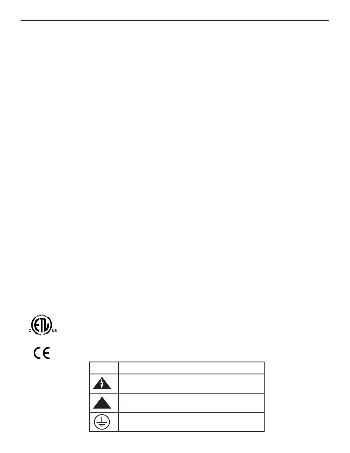
1.5 Agency Listings
Symbol Explanation
!
WARNING, risk of electric shock
CAUTION, refer to users’ guide
GROUND, PROTECTIVE CONDUCTOR TERMINAL
Flex-Pro
This pump is ETL listed to conforms to the following:
UL Standard 778 as a motor operated water pump
CSA Standard C22.2 as process control equipment
This pump complies to the Machinery Directive 98/37/EC, BS EN 60204-1, Low Voltage Directive
73/23/EC BS EN 61010-1, EMC Directive 89/336/EC, BS EN 50081-1/BS EN 50082-1.
Page 6
Page 6
2.0 Installation
2.1 Mounting Location
Choose an area located near chemical supply tank, chemical injection point, and electrical supply. Install pump
where it can be easily serviced.
!
316SS Mounting brackets are included. Mount pump to a secure surface using enclosed mounting hardware.
!
Mount pump close to injection point. Keep inlet (suction) and outlet (discharge) tubing as short as possible.
Longer discharge tubing increases back pressure at pump head.
!
A back flow prevention check valve is recommended at the discharge of the pump to prevent system fluid from
flowing back through the pump during tube replacement or if the tube should rupture.
!
A pressure relief valve is recommended at the discharge of the pump to prevent premature wear and damage to
the pump tube in the event the discharge line becomes blocked.
!
The Flex-Pro does not require back pressure. Pressure regulator valves are not required. Keep the discharge
pressure as low as possible to maximize tube life.
!
An anti-syphon valve is not required. Syphoning cannot occur.
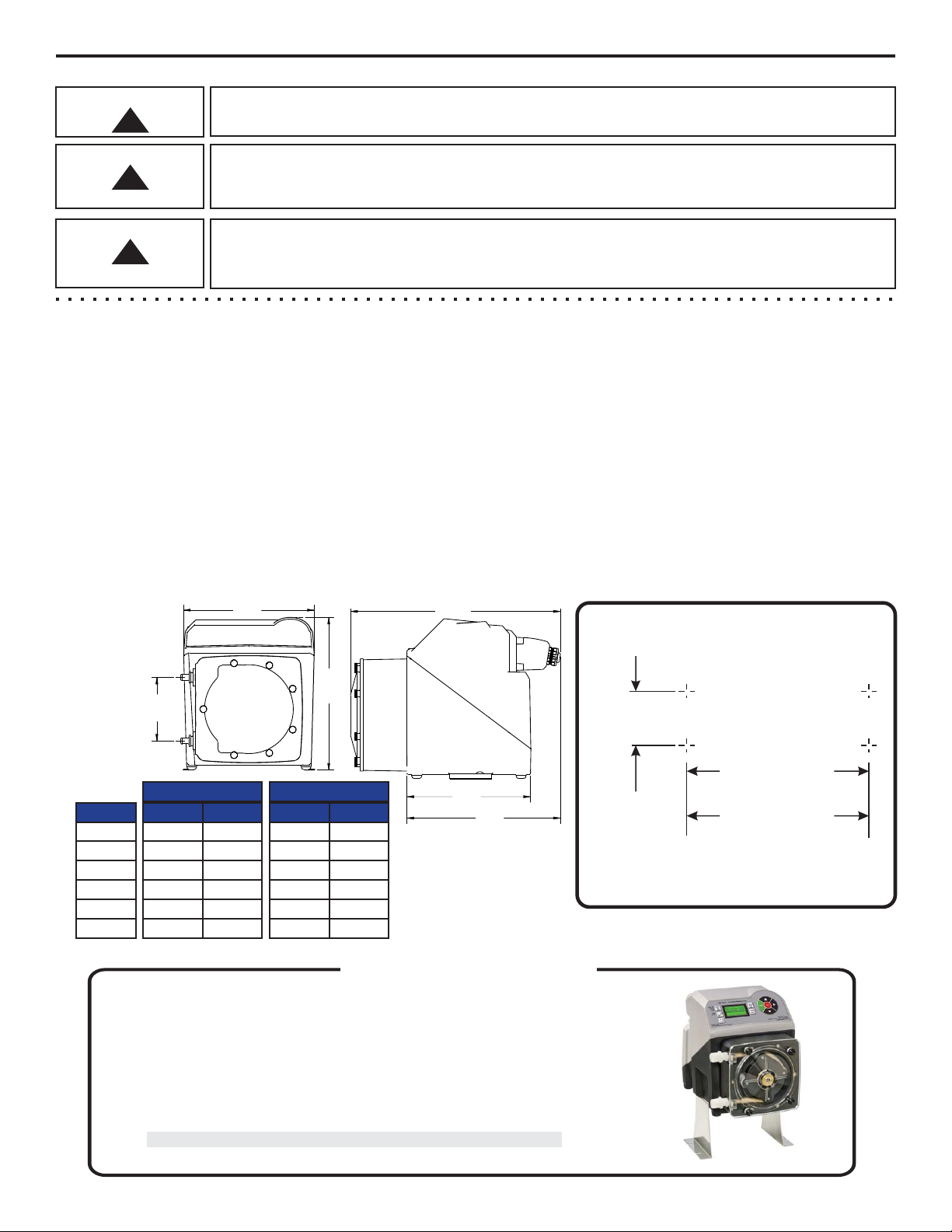
2.2Dimensions
Flex-Pro
All diagrams are strictly for guideline purposes only. Always consult an expert before
installing metering pump on specialized systems. Metering pump should be serviced by
qualified persons only.
n Raise metering pump 4-1/2 inches (11.43 cm) off ground or a surface.
n Made out of tough Stainless Steel.
n Provides a stable mounting surface.
Stainless Steel extended brackets allow pump to be securely mounted to most any surface;
floor, shelf, or skid. Brackets lift pump up 4-1/2 inches (11.43 cm), for easy pump access in
hard to reach areas.
Model #
72000-380
Description
Extended Mounting Bracket, 1 Pair, SS, 4 SS Screws
OptionalExtended Brackets
Model Number 72000-380
!
Always wear protective clothing, face shield, safety glasses and gloves when working on
or near your metering pump. Additional precautions should be taken depending on
solution being pumped. Refer to MSDS precautions from your solution supplier.
Risk of chemical overdose. Be certain pump does not overdose chemical during
backwash and periods of no flow in circulation system.
CAUTION
!
CAUTION
!
CAUTION
Dim
Inches
cm
A
B
C
D
E
10-3/4”
8-1/8”
15-1/4”
10”
12-1/4”
27.3
20.6
38.9
25.4
31.0
A3 Series
Inches
cm
14-1/4”
12-1/8”
18-5/8”
11”
13-5/8”
36.1
30.8
47.3
27.9
34.6
A4 Series
F
4-1/4”
10.7
6”
15.2
14.2"
(36.1cm)
6.0"
(15.2cm)
12.13"
30.8cm)
Front View
11.0"
(27.9cm)
13.63”
(34.6cm)
18.63”
(47.3cm)
Right View
A
B
F
C
D
E
Mounting Hole Spacings
(for standard and extended type brackets)
A4 Series
11.50” (29.2 cm)
A3 Series
8.25” (20.9 cm)
2.5” (6.35 cm)
Maximum bolt hole size
0.200” diameter (4 places)
Page 7
Page 7
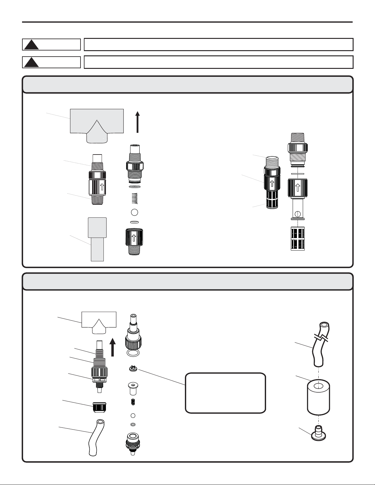
Flex-Pro
Discharge
Tubing
Tube retaining
nut
Injection
Check valve
Pipe tee
½” male NPT
1/4” male NPT
Discharge Injection / Check Valve
Discharge
Pipe or
½” Tubing
(not included)
Discharge Injection / Check Valve
Pipe
Tee
Install
upward
for best
results
½” Male NPT
½” Male NPT
or ½” Hose Barb
Suction Strainer
1/2” Male NPT Connection and 1/2”Hose Barb Models
Suction Tubing and Strainer
Ceramic
Weight
PVC Suction Tubing
3/8" OD x 1/4” ID
Polypropylene
Strainer
Duckbill is used to help reduce
calcium buildup when injecting
chemicals that calcify (such as
sodium hypochlorite). Duckbill
may add additional back
pressure to pump (up to 7 psi).
3/8”OD x 1/4” ID Tubing and Tri-Clamp connection Models
Proper eye and skin protection must be worn when installing and servicing pump.
!
CAUTION
This Pump Has Been Evaluated for Use with Water Only.
!
CAUTION
2.3 Installing Discharge Injection Fitting and Suction Strainer
PVDF
PVDF
Viton (optional EP)
T/FEP (optional EP)
Hastelloy C-276
Ceramic
Suction
Strainer
½” Male NPT
or ½” Hose Barb
PVDF
PVDF
Viton (optional EP)
Polypropylene
Removable
275 Micron
Filter
PVDF
Hastelloy C-276
PVDF
T/FEP (optional EP)
Ceramic
Viton (optional EP)
Santoprene
PVDF
Page 8
Page 8
2.4 Input Power Connections
Risk of electric shock – cord connected models are supplied with a grounding
conductor and grounding-
type attachment plug. To reduce risk of electric shock, be
certain that it is connected only to a pro
perly grounded, grounding-type receptacle.
Three power cord plug types available.
Power cord length is 6 feet (3.83 meters)
WARNING
! Be certain to connect pump to proper supply voltage. Using incorrect voltage will damage pump and may result in
injury. Voltage requirement is printed on pump serial label.
! Input power range is 96VAC to 264VAC 50/60 Hz.
! Voltage Selection is automatically detected and adjusted by power supply. No mechanical switch necessary.
! Use voltage your power cord is rated for.
! Cord connected models are supplied with a ground wire conductor and a grounding type attachment plug (power
cord). To reduce risk of electric shock, be certain that power cord is connected only to a properly grounded,
grounding type receptacle.
! Permanently connected models must be properly grounded. Be certain that a grounding conductor is connected
to terminal T11-1 located in the wiring compartment.
! Never strap control (input / output) cables and power cables together.
! Power Interruption: This pump has an auto-restart feature which will restore pump to operating state it was in
when power was lost.
Note: When in doubt regarding your electrical installation, contact a licensed electrician.
Electrical connections and grounding (earthing) must conform to local wiring codes.
Be certain that a
grounding conductor is connected to terminal T11-1 located in the
wiring compartment.
WARNING
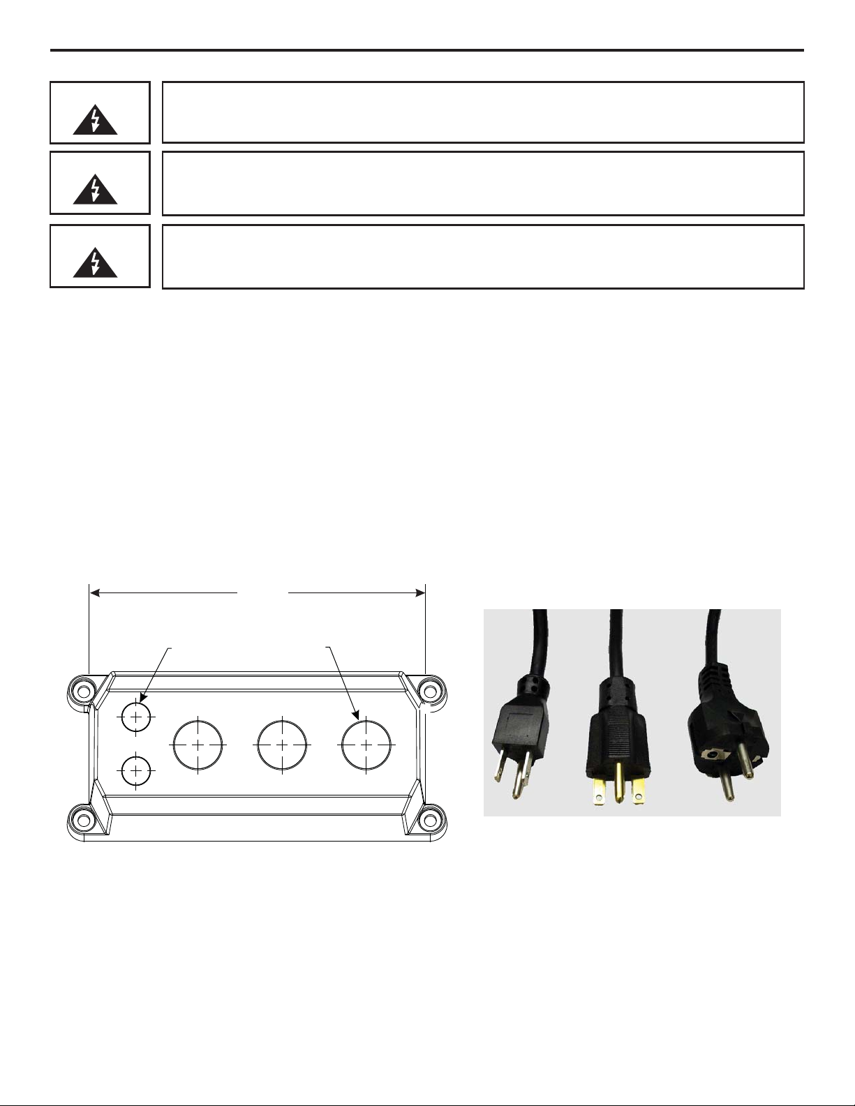
115V 60Hz
NEMA 5/15 (USA)
max: 125V AC
230V 60Hz
NEMA 6/15 (USA)
max: 250V AC
240V 50Hz
CEE 7/VII (EU)
max: 250V AC
QTY.
DESCRIPTION
2
.50 INCH (12.7 mm) LIQ-TIGHT HOLE PLUGS (MAT’L = NEOPRENE), PRE-INSTALLED
3
.875 INCH (22.2 mm) LIQ-TIGHT HOLE PLUGS (MAT’L = NEOPRENE), 2 PRE-INSTALLED
2
.50 INCH (12.7 mm) LIQ-TIGHT CONNECTORS FOR PASS THRU CORDS (MAT’L = NYLON)
ACCEPTABLE CABLE DIAMETER .118 TO .255 INCH (3.0 TO 6.5 MM), NOT INSTALLED
3
.875 INCH (22.2 mm) METALLIC LIQ-TIGHT CONNECTORS FOR PASS THRU CORDS (MAT’L = NYLON)
ACCEPTABLE CABLE DIAMETER .200 TO .395 INCH (5.1 TO =10.0 MM), 1 PRE-INSTALLED WITH POWER CORD MODELS
Cable and conduit connectors included
5.99 in.
(152.1 mm)
Ø
(12.7 mm)
2-PLCS.
.50
Ø
(21.3 mm)
3-PLCS.
.84 in.
WIRING COMPARTMENT COVER POWER CORD OPTIONS
Risk of electric shock - Disconnect electricity before removing the wiring
compartment cover.
WARNING
Flex-Pro
2
METALLIC LIQ-TIGHT CONNECTORS FOR .50 INCH FLEXIBLE CONDUIT (MAT’L = DIE CAST ZINC), NOT INSTALLED
Page 9
Page 9
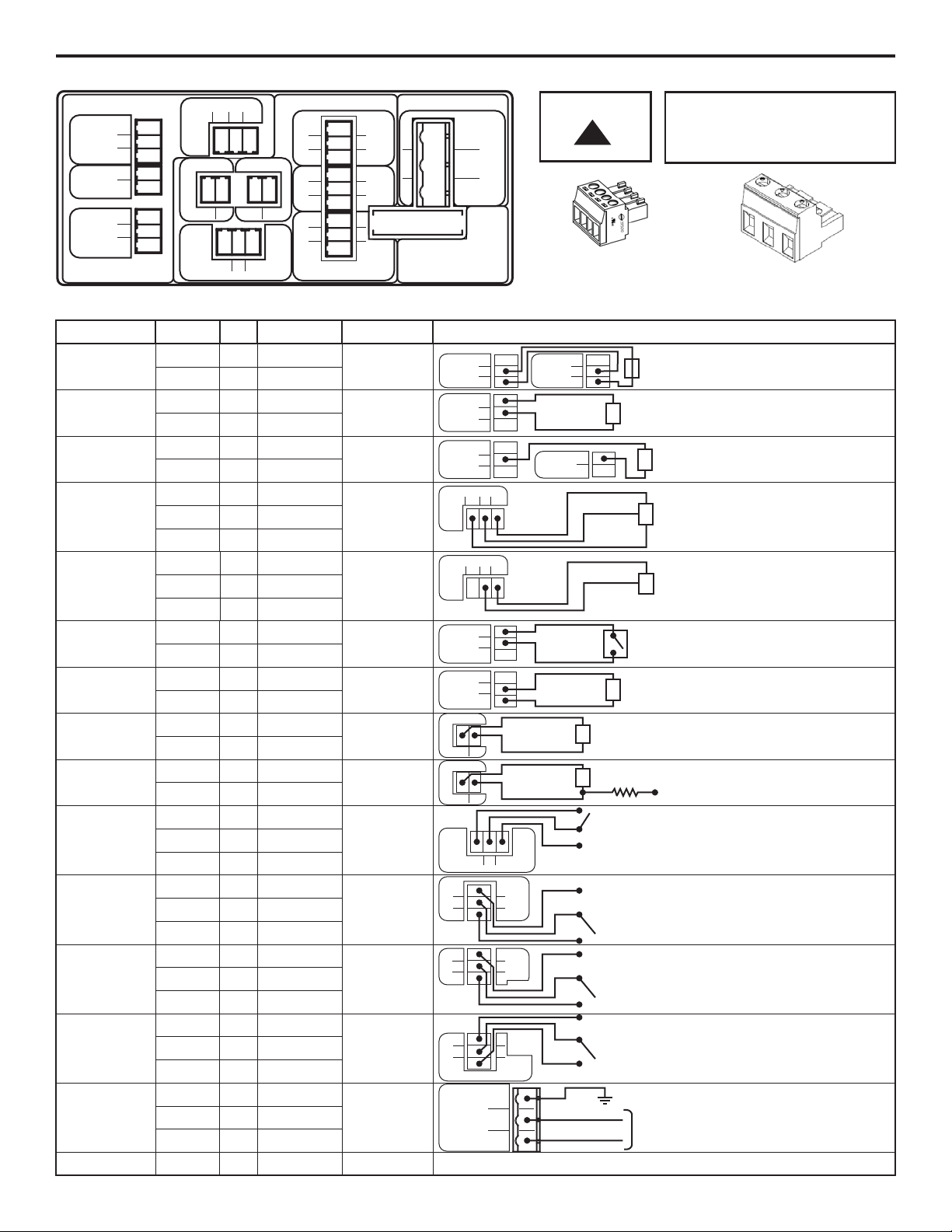
2.5 Wiring Terminals and I/O Schematics
Flex-Pro
OUTPUTINPUT
3
1
2
T3
DRY
RMT
COM
1
2
3
T1
PULSE
GND (-)
4-20 (+)
0-10 (+)
+15 VDC
1
2
T2
T4
3
1
2
(+)
FVS
SIG (-)
2
1
FREQ.
(-)
(+)
T5
1
2
4-20 mA
T6
POWER
FUSE 5A SLOW BLOW
(20 X 5MM)
F1
2
3
1
GROUND
N EUTRAL
(COMMON)
LINE
(HOT)
T11
N.C.
COM
N.O.
N.O.
COM
N.C.
CC3
CC2
T8
T9
3
1
2
3
1
2
3
1
2
CC1
N.O.
COM
N.C.
T10
1
2
3
N.C. COM. N.O.
RELAY
OUT
T7
(-)
(+)
INPUT:
4-20 mA
INPUT:
0-10V DC
INPUT:
FREQUENCY, AC
SINE WAVE, TTL,
CMOS
FUNCTION
TERMINAL PIN # RATING ELECTRICAL SP.
BLOCK DIAGRAM
T1
T1
T1
T1
T2
T1
INPUT:
FVS SYSTEM
(FLOW VERIFICATION
SENSOR)
FV SENSOR ONLY
T4
T4
T4
(+) POSITIVE
3
2
1
2
1
2
1
2
3
(-) NEGATIVE
(+) POSITIVE
(-) NEGATIVE
(+) POSITIVE
(-) NEGATIVE
(+) POSITIVE
SIGNAL
(-) NEGATIVE
INPUT:
REMOTE
START / STOP
(DRY CONTACT C.)
INPUT:
REMOTE
START / STOP
(WET CONTACT C.)
OUTPUT:
4-20 mA
OUTPUT:
FREQUENCY OPEN COLLECTOR
OUTPUT:
RELAY, 6 AMP
OUTPUT:
CONTACT
CLOSURE 1
INPUT:
POWER
OUTPUT:
CONTACT
CLOSURE 2
OUTPUT:
CONTACT
CLOSURE 3
FUSE
T3
T3
1
2
T3
T3
2
3
T6
T6
2
1
T5
T5
2
1
(+) POSITIVE
(-) NEGATIVE
(+) POSITIVE
(-) NEGATIVE
T7
1
T7
T7
2
3
NORM. CLOSED
COMMON
NORM. OPEN
T8
1
T8
T8
2
3
NORM. OPEN
COMMON
NORM. CLOSED
T9
1
T9
T9
2
3
NORM. OPEN
COMMON
NORM. CLOSED
T10
1
T10
T10
2
3
NORM. OPEN
COMMON
NORM. CLOSED
T11
1
T11
T11
2
3
GROUND
NEUTRAL
LINE (HOT)
F1
NA
5 AMP
120 OHM
IMPEDANCE, NON
POWERED LOOP
6 TO 30 VOLT DC
1 AMP MAX.
120 OHM
RESISTANCE
ACTIVE LOOP
OPEN COLLECTOR
0-1000 Hz
50% DUTY CYCLE
Form C
6 AMP MAX AT
250 VAC,
5 AMP MAX AT
30 VOLT DC
Form C
1 AMP MAX AT
125 VOLT AC,
0.8 AMP MAX AT
30 VOLT DC
Form C
1 AMP MAX AT
125 VOLT AC,
0.8 AMP MAX AT
30 VOLT DC
Form C
1 AMP MAX AT
125 VOLT AC,
0.8 AMP MAX AT
30 VOLT DC
5A SLOW BLOW
(20 X 5MM)
1
2
3
T1
PULSE
GND (-)
4-20 (+)
1
2
3
T1
PULSE
GND (-)
4-20 (+)
0-10 (+)
+15 VDC
1
2
T2
0-1000 HZ MAX.
(-) NEGATIVE
(+) POSITIVE
(+) POSITIVE
(-) NEGATIVE
NO VOLTAGE
96 TO 264 VOLT AC,
50 / 60 HZ
A3 = 220W
A4 = 350W
1
2
3
T1
PULSE
GND (-)
4-20 (+)
(+)
(-)
(+)
(-)
(+)
(-)
T4
3
1
2
(+)
FVS
SIG
(-)
RED (+)
BARE
BLACK (-)
3
1
2
T3
DRY
RMT
COM
3
1
2
T3
DRY
RMT
COM
(+)
(-)
(+)
(-)
2
1
FREQ.
(-)
(+)
T5
DIGITAL PULSE
RECEIVER CIRCUIT
1.5K OHM
(+)
(-)
EXTERNAL SOURCE
6-30V DC
1
2
3
N.C. COM. N.O.
RELAY
OUT
T7
NO
C
NC
SWITCH LOAD
6 AMP MAX @ 250V AC
5 AMP MAX @ 30V DC
2
3
1
GROUND
N EUTRAL
(COMMON)
LINE
(HOT)
T11
N.C.
COM
N.O.
T8
3
1
2
CC1
N.O.
COM
N.C.
CC2
T9
3
1
2
CC3
3
1
2
N.O.
COM
N.C.
T10
NO
C
NC
SWITCH LOAD
1 AMP MAX @ 125V AC
0.8 AMP MAX @ 30V DC
NO
C
NC
C
NC
NO
SWITCH LOAD
1 AMP MAX @ 125V AC
0.8 AMP MAX @ 30V DC
SWITCH LOAD
1 AMP MAX @ 125V AC
0.8 AMP MAX @ 30V DC
EXTERNAL DEVICE
6 TO 30V DC
OPEN CIRCUIT
IMPEDANCE MUST
BE GREATER THAN
50K OHM
BLUE-WHITE
FVS SENSOR
0-10V DC
TRANSMITTER
SOURCE
FREQUENCY
TRANSMITTER
SOURCE
ACTIVE 4-20mA
TRANSMITTER
SOURCE
2
1
4-20mA
(-)
(+)
T6
4-20mA RECEIVER
600 OHM LOAD MAX.
(+)
(-)
96 TO 264 VOLT AC,
50 / 60 HZ
A3 = 220W
A4 = 350W
Risk of electric shock - All
wiring must be insulated
and rated 300V minimum.
!
WARNING
Terminals T1 thru T10
Plug type
16 - 24 AWG
Power Input Terminal T11
Plug type
14 - 30 AWG
T4
T4
T4
1
2
3
(+) POSITIVE
SIGNAL
(-) NEGATIVE
T4
3
1
2
(+)
FVS
SIG
(-)
SIGNAL
NEGATIVE (-)
BLUE-WHITE
MICRO-FLO
FLOWMETER
PULSE OUTPUT
INPUT:
FVS SYSTEM
(FLOW VERIFICATION
SENSOR)
FS or FP MICRO-FLO
FLOWMETER ONLY
1
2
3
T1
PULSE
GND (-)
4-20 (+)
(OPTIONAL PUMP #2)
Single or dual pump (series)
input. Loop voltage must not
exceed 24 Volts.
Page 10
Peristaltic Metering Pump
Industries, Ltd.
ProSeries
by Blue-White Ind.
d
Per
statcMete
r
ngPum
p
Page 10
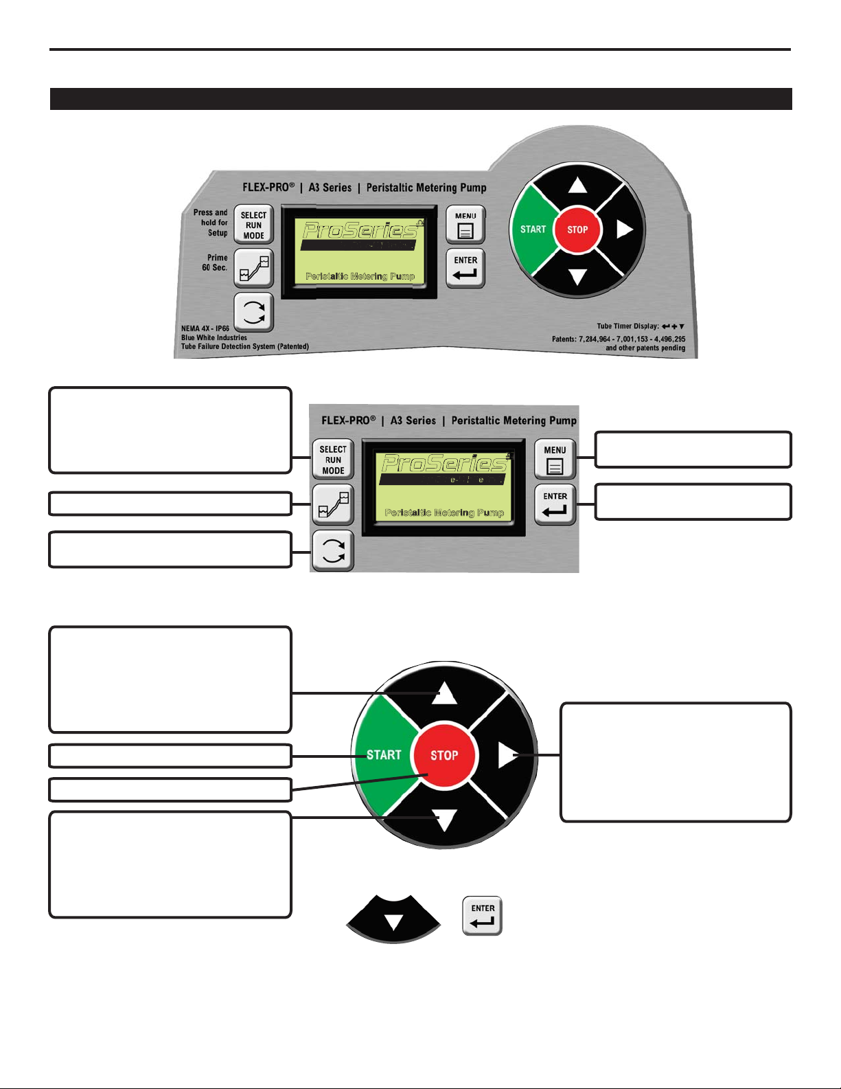
3.0 How To Operate Flex-Pro
Flex-Pro V Series, Control Panel - Button Operation
Peristaltic Metering Pump
Industries, Ltd.
ProSeries
by Blue-White Ind.
d
Peristaltic Metering Pump
Industries, Ltd.
ProSeries
by Blue-White Ind.
d
Flex-Pro
DOWN Arrow + ENTER
Flex-Pro has a built in Pump Tube Timer.
Timer starts when rotor is rotating and
stops when rotor is idle. To view current
Pump Tube Timer value, press ENTER and
DOWN arrow at same time while in the
normal operating mode. Screen will display
current Pump Tube Time in run-time hours.
While displayed, press ENTER button
twice to reset Pump Tube Timer to zero.
+
Press and release to select a Run
Mode.
Press and hold to enter the
configuration menu for the currently
active run mode only.
Press and release to prime the pump.
Press and release to change the roller
rotation.
Press and release to enter the
configuration menus.
Press and release to confirm a
menu selection.
Press and release to select menu
items, increase menu values by one,
and increase pump output in Manual
Speed Adjust mode.
Press and hold to increase values
progressively faster.
Press and release to stop the pump.
Press and release to select menu
items.
Press and release (when not in the
configuration menu) to toggle the
display units of measure and to
display the current input signal
values
Press and release to start the pump.
Press and release to select menu
items, decrease menu values by one,
and decrease pump output in Manual
Speed Adjust mode.
Press and hold to decrease values
progressively faster.
Page 11
Page 11
Flex-Pro
- Menu
+ Configuration
+ Input Setup
+ Pump Output
<- Esc
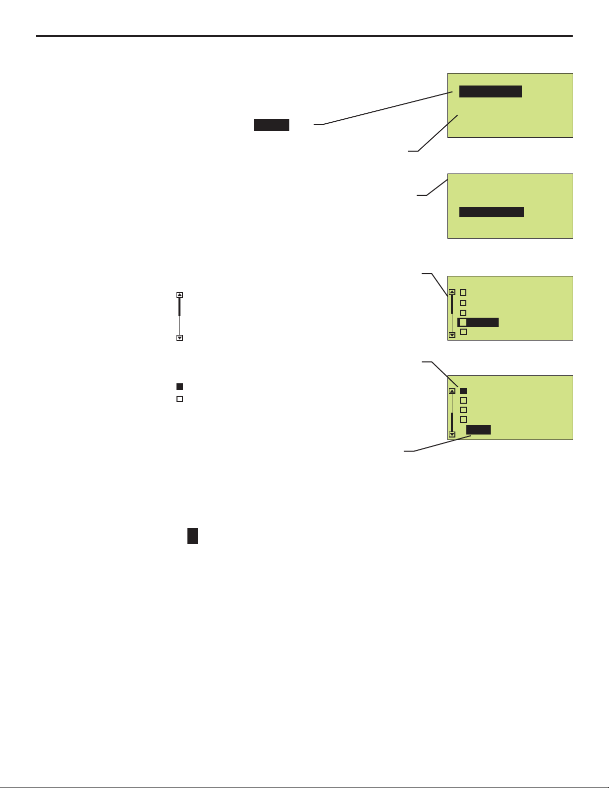
3.1 Menu Navigation
Use MENU button to enter menu for setting up pump.
Use UP or DOWN arrows to navigate through menu.
Active option appears on pump display in text.
Plus symbol
+ signifies top of a menu tree. This means you can go further
within menu.
Within Menu of pump, each screen you enter will have a title located along top.
This will display the menu that is currently active, or this will be the setting you
are configuring.
To back out of menu, select <- Esc line located at end of list. Then press
ENTER button. This will take you back one level.
When menu list extends above or below height of display, a scroll bar will
appear on left side. Press DOWN arrow to scroll down to end of list to see a list
of all available options.
Scroll bar example:
While making a selection where only one choice is allowed, you will see a radio
button.
Radio button example:
In a screen where you are making changes, you will see the word Done
located at bottom of list. You must select Done in order to leave screen
(whether you made a change or not). Selecting Done will take you back to
parent level.
When inputting a numerical value, use UP or DOWN arrow to scroll through 0 -
9. To move over to next digit use RIGHT arrow. If you pass your desired digit,
you can continuously press RIGHT arrow until you scroll reach to your desired
digit.
Numeric value example:
inverse
Solid black means item is selected
Outline with no fill means item is not selected
0000
– Sample screen shots –
- Configuration
+ Display Language
<- Esc
+ Reset to Factory Defaults
+ Set Password
+ Display Rate
- Display Rate
Oz/min
Liter/Hr
Gal/Hr (US)
Gal/day (US)
Done
- Display Rate
%Speed
RPM
ML/min
Liter/Hr
Oz/min
Page 12
Page 12
3.2 Configuration Menu
Below is menu structure for Configuration screens.
- Configuration
+ Display Language
+ Set Password
+ Display Rate
<- Esc
+ Reset to Factory Defaults
- Display Language
English
Spanish
German
Done
French
Display Language
- Display Language
- Configuration
+ Display Language
+ Display Rate
<- Esc
+ Reset to Factory Defaults
- Set Password
Enter Password:
OFF = 0000
Set Password
+ Set Password
English
Spanish
German
French
Done
0000
Press ENTER when done.
- Menu
+ Configuration
+ Input Setup
+ Pump Output
<- Esc
- Configuration
+ Display Language
<- Esc
+ Reset to Factory Defaults
Display Rate
+ Set Password
+ Display Rate
- Display Rate
%Speed
RPM
ML/min
Oz/min
- Set Password
Setting your password to:
Are you sure?
1234
Yes
No
- Configuration
+ Display Language
<- Esc
Reset to Defaults
+ Set Password
+ Display Rate
- Reset to Factory Defaults
+ Reset to Factory Defaults
Reset to Factory Defaults!
Are you sure?
Yes
No
Liter/Hr
Gal/Hr (US)
Gal/day (US)
Done
- Display Rate
Oz/min
Liter/Hr
Gal/Hr (US)
Gal/day (US)
Done
Hidden
Note: Scroll down using
DOWN arrow to see
“Hidden” menus on display.
- Menu
+ Configuration
+ Input Setup
+ Pump Output
<- Esc
- Configuration
+ Display Language
+ Set Password
+ Display Rate
<- Esc
+ Reset to Factory Defaults
- Display Language
English
Spanish
German
French
Done
3.2.1 Language Selection
Press MENU button to enter menu structure for setting up pump.
Select Configuration and Press ENTER button.
Select Display Language and Press ENTER button.
Select your desired language, then Press ENTER.
Note: English is default language.
Select Done at bottom of list to confirm your selection. Press ENTER button.
Select <-Esc on following screens to move back up to desired menu location.
Flex-Pro
Page 13

Page 13
Flex-Pro
- Configuration
+ Display Language
<- Esc
+ Set Password
+ Display Rate
+ Reset to Factory Defaults
- Reset to Factory Defaults
Reset to Factory Defaults!
Are you sure?
Yes
No
3.2.3 Reset Factory Defaults
This will reset pump to factory defaults. This will restore pump to original configuration when it left the factory.
Press MENU button to enter menu structure for setting up pump.
Select Configuration and Press ENTER button.
Select Reset to Factory Defaults and Press ENTER button.
Select No or Yes, then ENTER button.
Select <-Esc on the following screens to move back up to desired menu location.
3.2.2 Display Rate (Units of Measure)
By default, pump will display %Speed (motor speed) and RPM. It is recommended you select an additional Display Rate. After selecting another Display
Rate (such as ML/Min), pump will still display %Speed and RPM along with
your selected Display Rate.
Press MENU button to enter menu structure for setting up pump.
Select Configuration and Press ENTER button.
Select Display Rate and Press ENTER button.
Select your desired Display Rate (unit of measure). Note: %Speed and RPM
will always be active and available to view when pump is in operation.
Select Done at bottom of list to confirm your selection and to return back to
previous screen. Press ENTER button.
Select <-Esc on following screens to move back up to desired menu location.
- Configuration
+ Display Language
<- Esc
+ Reset to Factory Defaults
+ Set Password
+ Display Rate
- Display Rate
%Speed
RPM
ML/min
Oz/min
Liter/Hr
- Display Rate
Oz/min
Liter/Hr
Gal/Hr (US)
Gal/day (US)
Done
While pump is operating in any Run Mode, you can view
%Speed, RPM, plus another Display Rate (depending on
your selection above). Press RIGHT arrow while pump is
in any Run Mode. RIGHT arrow is a convenient way to
scroll through multiple read-only screens during normal
operating mode of pump.
Note: This is a read-only feature, no changes can be
made while in Run Mode.
Tip!
Page 14

Page 14
Flex-Pro
4.0 Input Setup
Below is menu structure for INPUT SETUP selection.the the
Max RPM cut-off - 4.1
To Select a maximum motor RPM.
Input the maximum RPM value.
Max Flowrate - 4.2
To calibrate your pump. This setting is
pre-configured at the factory based on
the tube size supplied when ordered.
Pump has been calibrated with water.
You can re-calibrate pump. Input the
calibrated ml/min at 100% motor speed.
Input Modes - 4.3
To configure your pump’s Run Modes.
Use this menu to setup your desired
operating mode. This manual will cover
each step in detail later.
Contact Input - 4.4
(remote start/stop)
Contact Closure Input feature is used to
Start and Stop pump remotely. Default
setting is DISABLE.
Set FVS - 4.5
(Flow Verification System)
Set Flow Verification time delay. Use this
feature if you are using a Blue-White
flow verification sensor to monitor flow
output. Default setting is OFF.
Set TFD - 4.6
(Tube Failure Detection)
Set Tube Failure Detection sensitivity.
Use this feature to increase the sensitivity to your chemical. Default setting is
75%.
Set Remote/Local control - 4.7
(Control panel touch pad lockout)
Select remote to disable the touch pad
buttons enabling input signal control
only. When remote is selected, the user
must select an input operating mode.
Select Local to disable all input signals
and allow local touch pad control only.
- Set FVS
- Max Flowrate
Input Max Flowrate:
Flowrate = ML/min
Press ENTER to set.
0000.01
- Contact Input
Close: Stop Pump
Open: Stop Pump
Input Time Delay:
OFF = 000
Range = 1-255 sec
Disable
000
- Input Setup
+ 4-20 mA Input
+ Frequency Input
+ Pulse Input
+ 0-10 VDC Input
+ Manual Adjust
+ Dispensing
+ Proportional
<- Esc
+ Manual Dosing
+ Cycle Adjustment
Hidden
Done
(select one)
+ Configuration
- Menu
+ Input Setup
+ Output Setup
<- Esc
+ Power Fail option
- Input Setup
+ Max RPM cut-off
+ Max Flowrate
+ Input Modes
+ Contact Input
+ Set FVS
<- Esc
Hidden
+ Remote/Local
+ Set TFD
- Input Setup
+ Max RPM cut-off
+ Max Flowrate
+ Input Modes
+ Contact Input
+ Set FVS
<- Esc
Hidden
+ Remote/Local
+ Set TFD
- Input Setup
+ Max RPM cut-off
+ Max Flowrate
+ Input Modes
+ Contact Input
+ Set FVS
<- Esc
Hidden
+ Remote/Local
+ Set TFD
- Input Setup
+ Max RPM cut-off
+ Max Flowrate
+ Input Modes
+ Contact Input
+ Set FVS
<- Esc
Hidden
+ Remote/Local
+ Set TFD
- Input Setup
+ Max RPM cut-off
+ Max Flowrate
+ Input Modes
+ Contact Input
+ Set FVS
<- Esc
Hidden
+ Remote/Local
+ Set TFD
- Input Setup
+ Max Flowrate
+ Input Modes
+ Contact Input
+ Set FVS
<- Esc
Hidden
+ Remote/Local
+ Set TFD
TFD Sensitivity
% Sensitivity:
Enter TFD Sensor
Sensitivity %.
78.00
- Input Setup
+ Input Modes
+ Contact Input
+ Set FVS
<- Esc
Hidden
+ Set TFD
+ Remote/Local
- Remote/Local
Remote Only
Local Only
Disable
Done
(select one)
- Remote Only Input Mode
4-20 mA
0-10 VDC
Frequency
(select one)
Hidden
Done
Proportional
Pulse
- Max RPM cut-off
25.01
Press ENTER to set.
Password Protect
Enter Password:
Use direction keys
8907
Press ENTER to set.
Page 15

Page 15
Flex-Pro
4.1 Max RPM cut-off
The maximum motor RPM can be limited to reduce the possibility of overfeeding
chemical into the system. Note that the pump’s display will still reference values
calculated from the 100% motor speed MAX Flowrate value (see section 4.2). Also,
the pump % motor speed will still be referenced from 125 RPM, the maximum
possible motor RPM. For example, if the pump speed is set for 25%, the display will
indicate 32.3 RPM. The prime mode RPM is limited to the Max RPM value.
Select Max RPM cut-off and Press ENTER button. Use the direction arrows to
enter the password 7890.
Press UP or DOWN arrow to scroll through 0 - 9 on selected digit.
Press RIGHT arrow to scroll over to next digit to right. If you pass your desired digit,
you can easily scroll back by continuously pressing RIGHT button.
Press ENTER to save changes.
Select <-Esc on the main menu screen to exit the menu and enter the run mode.
- Max RPM cut-off
- Input Setup
+ Max RPM cut-off
+ Max Flowrate
+ Input Modes
+ Contact Input
+ Set FVS
+ Set TFD
25.01
Press ENTER to set.
4.2 MAX Flowrate (output calibration)
The MAX Flowrate value is equal to the pump’s measured fluid output in milliliters
per minute, at the 100% motor speed adjustment setting. The pump uses the MAX
flow rate value to calculate motor speed for various operating functions and to
display output values.
Each Flex-Pro pump is calibrated at the factory and shipped with a calibrated pump
tube assembly installed. The MAX flow rate value can be adjusted at any time. To
achieve high accuracy, a field calibration under the actual operating conditions
should be performed and the Max Flowrate value changed to reflect the calibrated
amount. Multiply the Max Flowrate value by the percentage of error at your
calibrated flow rate to obtain the new Max Flowrate value.
Select Max Flowrate and Press ENTER button.
Press UP or DOWN arrow to scroll through 0 - 9 on selected digit.
Press RIGHT arrow to scroll over to next digit to right. If you pass your desired digit,
you can easily scroll back by continuously pressing RIGHT button.
Press ENTER to save changes.
Select <-Esc on the main menu screen to exit the menu structure and enter the run
mode.
Every pump tube assembly model number has a published maximum flow rate
value which is based on laboratory tests pumping water at room temperature at 36”
suction lift against 0 psi back pressure. Your actual output may vary due to fluid
viscosity, fluid temperature, suction lift height, piping system layout, manufacturing
tolerances and to a lesser degree, variations in system pressure and tubing wear.
To achieve high accuracy, the pump’s output should be measured (calibrated), and
the MAX Flowrate value (in milliliters per minute) updated, whenever any of the
following conditions exist:
! At the initial pump start up.
! When a new tube assembly is installed. Run the pump with or without fluid for
approximately 30 minutes prior to calibration.
! When the piping system configuration is changed.
! When the suction lift height is changed.
! Periodically during the life of the tube. Output variances are most noticeable prior
to tube failure.
- Input Setup
+ Max RPM cut-off
+ Max Flowrate
+ Input Modes
+ Contact Input
+ Set FVS
<- Esc
Hidden
+ Remote/Local
+ Set TFD
+ Set Rev Alarm
- Max Flowrate
Input Max Flowrate:
Flowrate = ML/min
Press ENTER to set.
0000.01
To calculate the Max
Flowrate:
To determine the amount of
error at your output setting,
divide the actual output
amount by the indicated
output. Then multiply the
resulting percentage of error
by the Max Flowrate value
currently showing in the pump.
Example: If the pump display
indicates the output is 170
ml/min but the actual
measured output is 160
ml/min, calculate the
percentage of error by:
160/170 = 0.941. Multiply the
Max Flowrate value by 0.941
and enter this new value.
Password Protect
Enter Password:
Use direction keys
8907
Press ENTER to set.
Page 16

Page 16
4.3.1 Manual Adjust (manual speed adjust)
Used to manually control speed of pump. Use up and down arrows to adjust
the speed while the pump is running or set % (percent) Motor Speed in this
menu.
Press SELECT RUN MODE button until Manual Speed Adjust is displayed in
the top line of the display.
To configure the pump output speed, navigate to Manual Speed Adjust menu
by using short-cut method described above, or by pressing MENU button, then
selecting Input Setup, Input Modes, and then Manual Adjust.
Press UP or DOWN arrow to scroll through 0 - 9 on selected digit.
Press RIGHT arrow to scroll over to next digit to right. If you pass your desired
digit, you can easily scroll back by continuously pressing RIGHT button.
Press ENTER to save changes.
If you used short-cut to enter Manual Speed Adjust setup, then just press and
hold Select Run Mode button until Run Mode screen is displayed.
If you used Menu button to navigate to Manual Speed Adjust setup, you must
navigate back out of menu structure. To do this you must select <-Esc at
bottom of every screen menu until you see Run Mode screen displayed.
Tip! This feature can be combined with Contact Input feature to allow for
remote Start and Stop of pump. Can be used with PLC, foot pedal, push
button, or other external controls.
Manual Speed Adjust
OFF
Manual Speed Adjust
Press START to run
Tip!
Run Mode
(operating Input Mode)
- Speed Adjust
Input Pump Speed:
Set % motor speed.
Press ENTER to set.
00.0%0
SELECT RUN MODE button also serves as a shortcut button.
Press and Hold SELECT RUN MODE button to enter program
menu for currently displayed Run Mode.
Once you have programed your Run Mode, Press ENTER to save
changes.
Press and Hold SELECT RUN MODE button to jump back to
current Run Mode of the pump.
Then Press START button to start pump with new settings applied.
In Manual Speed Adjust mode, you can view
pump output by pressing RIGHT arrow (see
screen shot). RIGHT arrow is a convenient
way to scroll through multiple read-only
screens during normal operating mode of
pump.
Tip!
Manual Speed Adjust
GAL/DAY
228
Å
É
Ä
È
Displays current rotor direction
Flex-Pro
4.3 Input Setup (operating mode configuration)
Page 17

Page 17
4.3.2 4 - 20 mA Input
Used to remotely control pump with an incoming 4-20 mA signal.
Default settings: 4 mA = 0% motor speed
20 mA = 100% motor speed
Press SELECT RUN MODE button until 4 - 20 mA Input is displayed in the top
line of the display.
To configure the pump, navigate to 4 - 20 mA Input menu by using short-cut
method described at beginning of section, or by pressing MENU button, then
selecting Input Setup, Input Modes, and then 2 - 20 mA Input.
Press UP or DOWN arrow to scroll through 0 - 9 on selected digit.
Press RIGHT arrow to scroll over to next digit to right. If you pass your desired
digit, you can easily scroll back by continuously pressing RIGHT button.
Press ENTER to save changes.
Continue this process until all four screens have been configured.
If you used short-cut to enter 4-20 mA input setup, then just press and hold
Select Run Mode button until Run Mode screen is displayed.
If you used Menu button to navigate to 4-20 mA input setup, you must navigate
back out of menu structure. To do this you must select <-Esc at bottom of every
screen menu until you see Run Mode screen displayed.
- 4-20 mA Input
% Motor @ Min Signal:
Input % Motor Speed at
Minimum mA Signal
00.0%0
- 4-20 mA Input
Min mA Signal:
Input Min. mA signal Input.
4.000
- 4-20 mA Input
% Motor @ Max Signal:
Input % Motor Speed at
Maximum mA Signal
00.0%1
- 4-20 mA Input
Max mA Signal:
Input Max. mA Signal Input
0.002
Press ENTER to set.
Press ENTER to set.
In 4 - 20 mA mode, you can view current
incoming signal by pressing RIGHT arrow (see
screen shot). RIGHT arrow is a convenient
way to scroll through multiple read-only
screens during normal operating mode of
pump.
Tip!
4-20 mA Input
mA
Displays current incoming signal
12.5
- Screen Shot -
Example 1
6
4
8
10
12
14
16
18
20
0
25
50
75
100
Pump
Motor Speed (%)
Milliamp input (mA)
from external source
4 mA = 0% Pump Output
20 mA = 100% Pump Output
Example 2
6
4
8
10
12
14
16
18
20
0
25
50
75
100
4 mA = 100% Pump Output
20 mA = 0% Pump Output
Example 3
6
4
8
10
12
14
16
18
20
0
25
50
75
100
4 mA = 20% Pump Output
16 mA = 43.8% Pump Output
Å
É
Ä
È
Displays current rotor direction
0%
Output
Pump
Motor Speed (%)
Pump
Motor Speed (%)
100%
Output
100%
Output
0%
Output
43.8%
Output
20%
Output
Milliamp input (mA)
from external source
Milliamp input (mA)
from external source
Flex-Pro
Page 18

Page 18
4.3.3 0 - 10 VDC Input (Volt DC)
Used to remotely control pump with an incoming 0-10 VDC signal.
Default settings: 0 VDC = 0% motor speed
10 VDC = 100% motor speed
Press SELECT RUN MODE button until 0 - 10 VDC Input is displayed in the top
line of the display.
To configure the pump, navigate to 0 - 10 VDC Input menu by using short-cut
method described at beginning of section, or by pressing MENU button, then
selecting Input Setup, Input Modes, and then 0 - 10 VDC Input.
Press UP or DOWN arrow to scroll through 0 - 9 on selected digit.
Press RIGHT arrow to scroll over to next digit to right. If you pass your desired
digit, you can easily scroll back by continuously pressing RIGHT button.
Press ENTER to save changes.
Continue this process until all four screens have been configured.
If you used short-cut to enter 0 - 10 VDC Input setup, then just press and hold
Select Run Mode button until Run Mode screen is displayed.
If you used Menu button to navigate to 0 - 10 VDC Input setup, you must
navigate back out of menu structure. To do this you must select <-Esc at bottom
of every screen menu until you see Run Mode screen displayed.
- 0-10 VDC Input
% Motor @ Min Signal:
Input % Motor Speed at
Minimum Volt DC Signal
00.0%0
- 0-10 VDC Input
Min VDC Signal:
Input Min. Volt DC signal
0.000
- 0-10 VDC Input
% Motor @ Max Signal:
Input % Motor Speed at
Max VDC Signal
00.0%1
- 0-10 VDC Input
Max VDC Signal:
Input Max. Volt DC signal
0.001
Press ENTER to set.
Press ENTER to set.
In 0 - 10 VDC mode, you can view current
incoming signal by pressing RIGHT arrow (see
screen shot). RIGHT arrow is a convenient
way to scroll through multiple read-only
screens during normal operating mode of
pump.
Tip!
0-10 VDC Input
VDC
Displays current incoming signal
12.5
- Screen Shot -
Å
É
Ä
È
Displays current rotor direction
Example 1
0
2
4
6
8
10
0
25
50
75
100
Pump
Motor Speed (%)
VDC Input
from external source
0 VDC = 0% Pump Output
10 VDC = 100% Pump Output
Example 2
0
25
50
75
100
0 VDC = 100% Pump Output
10 VDC = 0% Pump Output
Example 3
0
25
50
75
100
0 VDC = 20% Pump Output
8 VDC = 45.3% Pump Output
0%
Output
Pump
Motor Speed (%)
Pump
Motor Speed (%)
100%
Output
100%
Output
0%
Output
45.3%
Output
0
2
4
6
8
10
VDC Input
from external source
0
2
4
6
8
10
VDC Input
from external source
20%
Output
Flex-Pro
Page 19

Page 19
4.3.4 Frequency Input (Hz)
Used to remotely control pump with an incoming high speed frequency signal.
Typically used with flow meters or other external devices.
Default settings: 0 Frequency (Hz) = 0% motor speed
1000 Frequency (Hz) = 100% motor speed
Press SELECT RUN MODE button until Frequency Input is displayed in the
top line of the display.
To configure the pump, navigate to Frequency Input menu by using short-cut
method described at beginning of section, or by pressing MENU button, then
selecting Input Setup, Input Modes, and then Frequency Input.
Press UP or DOWN arrow to scroll through 0 - 9 on selected digit.
Press RIGHT arrow to scroll over to next digit to right. If you pass your desired
digit, you can easily scroll back by continuously pressing RIGHT button.
Press ENTER to save changes.
Continue this process until all four screens have been configured.
If you used short-cut to enter Frequency Input setup, then just press and hold
Select Run Mode button until Run Mode screen is displayed.
If you used Menu button to navigate to Frequency Input setup, you must
navigate back out of menu structure. To do this you must select <-Esc at bottom
of every screen menu until you see Run Mode screen displayed.
- Frequency Input
% Motor @ Min Signal:
Input % Motor Speed at
Minimum Freq. (Hz) Signal
00.0%0
- Frequency Input
Min Frequency Signal:
Input Min. Freq. (Hz) signal
0000
- Frequency Input
% Motor @ Max Signal:
Input % Motor Speed at
Maximum Freq. (Hz) Signal
00.0%1
- Frequency Input
Max Frequency Signal:
Input Max. Freq. (Hz) signal
0001
Press ENTER to set.
Press ENTER to set.
Injection
Point
S3 Series | Hybrid Ultrasonic Flowmeter
NEMA 4X
IP 66
Industries, Ltd.
ProSeries
by Blue-White Ind.
TM
Doppler /
Transit Time
Discharge
Line
Paddlewheel
Flow Sensor / Meter
Ultrasonic
Flow Meter
Injection
Point
Example #1, Ultrasonic flow meter Example #2, Paddlewheel flow meter
Discharge
Line
or
0
200
400
600
800
1000
0
25
50
75
100
Pump
Motor Speed (%)
Frequency Input (Hz)
0 Hz = 0% Pump Output
1000 Hz = 100% Pump Output
0
25
50
75
100
0 Hz = 100% Pump Output
1000 Hz = 0% Pump Output
0
25
50
75
100
0 Hz = 20% Pump Output
800 Hz = 50% Pump Output
0%
Output
Pump
Motor Speed (%)
Pump
Motor Speed (%)
100%
Output
100%
Output
0%
Output
50%
Output
0
200
400
600
800
1000
0
200
400
600
800
1000
20%
Output
Frequency Input (Hz) Frequency Input (Hz)
Examples:
Flex-Pro
Page 20

Page 20
4.3.5 Pulse Batch (low speed pulse)
Used to remotely control pump with an incoming pulse signal. Can be used with
an external foot pedal, a water meter, a PLC, contact closure, or other low speed
pulse devices.
Default settings: 1 Pulse = 100% motor speed for 2.5 seconds
Press SELECT RUN MODE button until Pulse Batch is displayed in the top line
of the display.
To configure the pump, navigate to Pulse Batch menu by using short-cut
method described at beginning of section, or by pressing MENU button, then
selecting Input Setup, Input Modes, and then Pulse Batch.
Press UP or DOWN arrow to scroll through 0 - 9 on selected digit.
Press RIGHT arrow to scroll over to next digit to right. If you pass your desired
digit, you can easily scroll back by continuously pressing RIGHT button.
Press ENTER to save changes.
Continue this process until all four screens have been configured.
If you used short-cut to enter Pulse Batch setup, then just press and hold Select
Run Mode button until Run Mode screen is displayed.
If you used Menu button to navigate to Pulse Batch setup, you must navigate
back out of menu structure. To do this you must select <-Esc at bottom of every
screen menu until you see Run Mode screen displayed.
- Pulse Batch
% Motor Speed @ Batch:
% Motor during batch.
00.0%1
- Pulse Batch
Input Pulse Number:
Pulse Number for batch
0010
- Pulse Batch
Pump On Time:
Run time during batch.
02.50
Press ENTER to set.
Max = 999999.9 Seconds
Press ENTER to set.
In Pulse Batch mode, you can view current
incoming signal count by pressing RIGHT
arrow (see screen shot). RIGHT arrow is a
convenient way to scroll through multiple readonly screens during normal operating mode of
pump.
Tip!
Pulse Batch
Pulse Number: 0
Run Time (SEC): 2.5
- Screen Shot -
Displays current incoming signal
In Frequency Input mode, you can view
current incoming signal by pressing RIGHT
arrow (see screen shot). RIGHT arrow is a
convenient way to scroll through multiple readonly screens during normal operating mode of
pump.
Tip!
300
Frequency Input
Hz
Displays current incoming signal
- Screen Shot -
Å
É
Ä
È
Displays current rotor direction
Flex-Pro
Page 21

Page 21
4.3.6 Manual Cycle Adjust (repeating cycle timer)
Used to run at a pre-selected motor speed for a specified run time. This cycle
will repeat itself using a repeating cycle timer.
Default settings: 100% motor speed for 1.5 seconds
Repeating cycle timer = 4 seconds
Press SELECT RUN MODE button until Manual Cycle Adjust is displayed in
the top line of the display.
To configure the pump, navigate to Manual Cycle Adjustment menu by using
short-cut method described at beginning of section, or by pressing MENU
button, then selecting Input Setup, Input Modes, and then Cycle Adjustment.
Press UP or DOWN arrow to scroll through 0 - 9 on selected digit.
Press RIGHT arrow to scroll over to next digit to right. If you pass your desired
digit, you can easily scroll back by continuously pressing RIGHT button.
Press ENTER to save changes.
Continue this process until all three screens have been configured.
If you used short-cut to enter Manual Cycle Adjustment setup, then just press
and hold Select Run Mode button until Run Mode screen is displayed.
If you used Menu button to navigate to Cycle Adjustment setup, you must
navigate back out of menu structure. To do this you must select <-Esc at bottom
of every screen menu until you see Run Mode screen displayed.
- Cycle Adjust.
Input Duty On-Time:
Run-Time per cycle.
01.50
- Cycle Adjust.
Input Pump Speed:
Set % pump speed.
00.0%0
- Cycle Adjust.
Total Cycle Time:
Repeating Timer.
04.00
Press ENTER to set.
Max = 999999.9 Seconds
Max = 999999.9 seconds
Cycle (SEC.): 4.0
On Time (SEC.) 1.5
Manual Cycle Adjust
In Manual Cycle Adjust mode, you can view
current settings by pressing RIGHT arrow (see
screen shot). RIGHT arrow is a convenient
way to scroll through multiple read-only
screens during normal operating mode of
pump.
Tip!
- Screen Shot -
1.5 Sec. On-Time
(Chemical Feed)
Injection Point
Graphical representation of Manual Cycle Adjust injection characteristics.
Note: Your chemical or solution is mixed in fluid. This image is only illustrating feed characteristics.
4 Second Total Cycle Time
(Repeating Timer)
4 Second Total Cycle Time
(Repeating Timer)
1.5 Sec. On-Time
(Chemical Feed)
Flex-Pro
Page 22

Page 22
- Dispensing
Input Pump Speed:
Set % pump speed.
Press ENTER to set.
50.0%0
- Dispensing
Volume to Dispense:
Input mL to dispense.
001000.0
Press ENTER to set.
4.3.7 Dispensing
Configure any dispensing amount or sample size and pump will repeat it on
command by pressing START button. Great for accurate single shot dispensing
of a pre-configured volume.
Default settings: 1000 milliliters
50% pump speed
Press SELECT RUN MODE button until Dispensing is displayed in the top line
of the display.
To configure the pump, navigate to Dispensing menu by using short-cut method
described at beginning of section, or by pressing MENU button, then selecting
Input Setup, Input Modes, and then Dispensing.
Press UP or DOWN arrow to scroll through 0 - 9 on selected digit.
Press RIGHT arrow to scroll over to next digit to right. If you pass your desired
digit, you can easily scroll back by continuously pressing RIGHT button.
Press ENTER to save changes.
Continue this process until all two screens have been configured.
If you used short-cut to enter Dispensing setup, then just press and hold Select
Run Mode button until Run Mode screen is displayed.
If you used Menu button to navigate to Dispensing setup, you must navigate
back out of menu structure. To do this you must select <-Esc at bottom of every
screen menu until you see Run Mode screen displayed.
In Dispensing mode, you can view current
incoming signal count by pressing RIGHT
arrow (see screen shot). RIGHT arrow is a
convenient way to scroll through multiple readonly screens during normal operating mode of
pump.
Tip!
1500
ML
Dispensing
Å
É
Ä
È
Displays current rotor direction
Flex-Pro
Page 23

Page 23
4.3.8 Manual Dosing
Used to configure Parts Per Million dosing to a system. This method can be
used if treated fluid volume is a fixed amount (in Liters Per Minute). If treated
fluid volume is variable (continuous change), then use of a flow meter is recommended along with pumps Proportional Mode (next Run Mode).
Default settings: 12.5% dose solution concentration
1.25 dose solution Specific Gravity
10 LPM (liters per minute) fluid volume to be treated
1.0 Parts Per Million to dose
Press SELECT RUN MODE button until Manual Dosing is displayed in the top
line of the display.
To configure the pump, navigate to Manual Dosing menu by using short-cut
method described at beginning of section, or by pressing MENU button, then
selecting Input Setup, Input Modes, and then Manual Dosing.
Press UP or DOWN arrow to scroll through 0 - 9 on selected digit.
Press RIGHT arrow to scroll over to next digit to right. If you pass your desired
digit, you can easily scroll back by continuously pressing RIGHT button.
Press ENTER to save changes.
Continue this process until all four screens have been configured.
If you used short-cut to enter Manual Dosing setup, then just press and hold
Select Run Mode button until Run Mode screen is displayed.
If you used Menu button to navigate to Manual Dosing setup, you must navigate
back out of menu structure. To do this you must select <-Esc at bottom of every
screen menu until you see Run Mode screen displayed.
- Manual Dosing
Dose Specific Gravity:
Specific Gravity of solution.
Press ENTER to set.
.251
- Manual Dosing
Dose Concentration:
% of concentration.
2.5%1
- Manual Dosing
PPM to dose:
Parts Per Million to dose.
000.0 - 100.0 PPM
- Manual Dosing
Fluid Volume (LPM):
Fluid to be treated.
Press ENTER to set.
1.0 - 9999.9 LPM
0
0010.00
001.0
In Manual Dosing mode, you can view current
settings by pressing RIGHT arrow (see screen
shot). RIGHT arrow is a convenient way to
scroll through multiple read-only screens
during normal operating mode of pump.
Tip!
- Screen Shot -
Manual Dosing
% Concentration: 12.5
Spec. Gravity: 1.25
Flex-Pro
Page 24

Page 24
4.3.9 Proportional Dosing
Used to configure proportional Parts Per Million dosing to a system. This method
of proportional dosing is based off input pump is receiving from an external flow
meter. Flow meter must have a pulse output. You will need to refer to flow meter
instruction manual to obtain K-factor for flow meter.
Default settings: 12.5% dose solution concentration
1.25 dose solution Specific Gravity
5.0 K-factor (Pulses Per Liter),
see flow meter instruction manual
1.0 Parts Per Million to dose
Press SELECT RUN MODE button until Proportional Dosing is displayed in
the top line of the display.
To configure the pump, navigate to Proportional Dosing menu by using shortcut method described at beginning of section, or by pressing MENU button, then
selecting Input Setup, Input Modes, and then Proportional.
Press UP or DOWN arrow to scroll through 0 - 9 on selected digit.
Press RIGHT arrow to scroll over to next digit to right. If you pass your desired
digit, you can easily scroll back by continuously pressing RIGHT button.
Press ENTER to save the changes.
Continue this process until all four screens have been configured.
If you used short-cut to enter Proportional Dosing setup, then just press and hold
Select Run Mode button until Run Mode screen is displayed.
If you used Menu button to navigate to Proportional Dosing setup, you must
navigate back out of menu structure. To do this you must select <-Esc at bottom
of every screen menu until you see Run Mode screen displayed.
- Proportional Dosing
Input K-Factor (pulses):
Pulses Per Liter.
0.0001 - 9999.9999
- Proportional Dosing
Dose Specific Gravity:
Specific Gravity of solution.
Press ENTER to set.
.251
- Proportional Dosing
Dose Concentration:
Percentage of concentration.
Press ENTER to set.
- Proportional Dosing
PPM to dose:
Parts Per Million to dose.
000.0 - 100.0 PPM
012.5%
0005.0000
001.0
Injection
Point
S3 Series | Hybrid Ultrasonic Flowmeter
NEMA 4X
IP 66
Industries, Ltd.
ProSeries
by Blue-White Ind.
TM
Doppler /
Transit Time
Discharge
Line
Paddlewheel
Flow Sensor / Meter
Ultrasonic
Flow Meter
Injection
Point
Example #1, Ultrasonic flow meter Example #2, Paddlewheel flow meter
Discharge
Line
or
Flex-Pro
Page 25

Page 25
- Menu
+ Configuration
+ Input Setup
+ Pump Output
<- Esc
- Input Setup
+ Contact Closure Input
- Contact Closure Input
Close: Stop Pump
Open: Stop Pump
<- Esc
Hidden
+ Motor - Select RPM
+ Tubing - Max Flowrate
+ Set FVS
+ Operating Input Modes
Disable
Done
4.4 Contact Closure Input
Used to remotely start and stop pump using a close=stop or open=stop signal. If
pump should start on an open, then select “Close: Stop Pump” option. Can be
used with an external foot pedal, a PLC, contact closure, or other similar
external devices.
Default settings: Disable
CC Input Range: 6 - 30 VDC
or
Dry Contact Closure (no voltage required)
[See section 5.1 for wire connections]
Navigate to Contact Input menu by MENU button, then selecting Input Setup,
and then Contact Input.
Press UP or DOWN arrow to scroll through your options.
Press ENTER to make a selection. You should then notice radio button (square
box) is now filled in next to your selection.
Press DOWN arrow to scroll down to Done selection. Then press ENTER.
To navigate back out of menus, select <-Esc and press the ENTER button at
bottom of every screen menu until you see Run Mode screen displayed.
IMPORTANT: If Contact Closure Input is enabled, pump will display STANDBY if
pump is in Stop mode via the Contact Closure. Please use caution in this
mode. Pump can Start at anytime. If you must perform maintenance to the
pump, Press STOP button.
When Contact Closure Input is enabled, the word Remote will be displayed on
lower left side of screen at all times.
- Sample Screen Shots -
In Proportional Dosing mode, you can view
current incoming signal count and settings by
pressing RIGHT arrow (see screen shots).
RIGHT arrow is a convenient way to scroll
through multiple read-only screens during
normal operating mode of pump.
Tip!
Proportional Dosing
- Screen Shot -
Proportional Dosing
- Screen Shot -
% Concentration: 12.5
Spec. Gravity: 1.25
300
Hz
Displays current incoming signal
Å
É
Ä
È
Displays current rotor direction
Manual Speed Adjust
GAL/DAY
228
Å
É
Ä
È
REMOTE
Signal started pump
Flex-Pro
Manual Speed Adjust
Waiting for SIGNAL...
STANDBY
REMOTE
Signal stopped pump
Page 26

Page 26
4.5 Set FVS (Flow Verification System)
Used to monitor pump output. If pump does not dispense fluid when pump
head rotor is turning, pump will go into an alarm mode and stop pump. BlueWhite offers a flow verification sensor that can easily attach to fitting on pump.
Default settings: 000 (off)
Navigate to Set FVS menu by pressing MENU button, then selecting Input
Setup, and then Set FVS.
Press UP or DOWN arrow to scroll through 0 - 9 on selected digit.
Press RIGHT arrow to scroll over to next digit to right. If you pass your desired
digit, you can easily scroll back by continuously pressing RIGHT button.
Press ENTER to save changes and exit FVS screen.
To navigate back out of menus, select <-Esc and press ENTER button at
bottom of every screen menu until you see Run Mode screen displayed.
Flow Verification System (sensor sold separately)
A3 is equipped with a Flow Verification System which is designed to stop pump
and provide a contact closure output or 10 amp relay output (setup in software)
in event sensor does not detect chemical during pump operation. This could
indicate a clogged injection fitting, empty chemical solution tank, worn pump
tube, loose tubing connection, etc.
To allow pump to clear any gasses that may have accumulated during stopper
operation (such as with chlorine), an alarm delay time value from 1-255
seconds must be programmed (An alarm delay value of 000 seconds disables
FVS system).
If FVS alarm occurs, pump will stop, send an external signal (if setup), and
screen will flash FVS with an alarm icon.
To clear FVS alarm, you must press START button or re-cycle power (unplug
power to pump, then plug back in).
Install FVS Flow Sensor - Flow Verification Sensor (FVS) should be installed
on the inlet (suction) side of the pump tube. Sensor includes a PVC tubing
insert, located inside sensors female thread connection, that is designed to
seal sensor onto pump tube inlet adapter. Thread sensor onto pump tube until
tubing insert is snug against pump tube inlet fitting - do not over-tighten.
- Set FVS
- Input Setup
+ Set FVS
<- Esc
Hidden
+ Contact Closure Input
+ Motor - Select RPM
+ Tubing - Max Flowrate
+ Operating Input Modes
Input FVS Time Delay:
OFF = 000
Range = 001-255 seconds
000
Seconds
Confirm the FVS flow range - Flow Verification Sensor (FVS) will only
function within its operating range. Sensor model FV-100 has an operating
range of 30-300 ml/min (1-10 oz/min) when used as a flowmeter. However, due
to pressure drop across the sensor, the pump’s suction capability is limited to
14.7 psi. Therefore, when used with the peristaltic pump as a flow verification
sensor, the effective operating range is reduced to 30-200 ml/min. Note that if
the pump’s output is less than 30 ml/min, the sensor will not detect chemical
and a signal will not be sent to pump.
PUBLISHED
FLOW RANGE
(ml/min)
100-1000
FV-200
200-2000
FV-300
300-3000
FV-400
500-5000
FV-500
700-7000
FV-600
SENSOR
MODEL
NUMBER
Flex-Pro
FVS
ALARM
When a FVS alarm occurs
STOP
30-300
FV-100
ACTUAL WORKING RANGE
WITH FLEX-PRO PUMP
(ml/min)
50-900
100-1800
300-3000
500-5000
700-7000
30-200
Page 27

Page 27
Flex-Pro
!
CAUTION
4.6.1 TFD Adjustment
Flex-Pro Tube Failure Detection (TFD) sensitivity can be adjusted through the
menu. Default setting (75% sensitivity) will trigger an alarm with most water
treatment chemicals with no false triggering.
TFD sensitivity range = 75% to 100%
To set TFD sensitivity, press ENTER when INPUT SETUP is highlighted. Scroll
down and highlight SET TFD and press ENTER
To increase sensitivity, press UP arrow.
To decrease sensitivity, press DOWN arrow.
- Input Setup
Enter TFD Sensor
Sensitivity %
TFD Sensitivity
% Sensitivity:
075.0
+ Set FVS
+ Set TFD
+ Input Setup
+ Contact Input
+ Set FVS
- Menu
+ Configuration
+ Input Setup
+ Output Setup
<- Esc
It is recommended to leave default setting at 75% sensitivity. This will
eliminate your chance of false triggers.
Only increase sensitivity if the solution your pumping does not trigger the
TFD alarm at 75% sensitivity.
4.6 TFD (Tube Failure Detection)
Flex-Pro is equipped with a Tube Failure Detection System which is designed to
stop pump and provide an output alarm (see Output menu) in the event pump
tube should rupture and chemical enters pump head. This patented system is
capable of detecting presence of a large number of chemicals including Sodium
Hypochlorite (Chlorine), Hydrochloric (muriatic) Acid, Sodium Hydroxide, and
many others. System will not be triggered by water (rain, condensation, etc.) or
silicone oil (roller and tubing lubricant).
If system has detected chemical, pump tube must be replaced and pump head
and roller assembly must be thoroughly cleaned. Failure to clean the roller
assembly will void warranty.
If TFD alarm occurs, pump will stop, close an alarm outputl (if configured), and
screen will flash TFD with an alarm icon.
Confirm Chemical Detection - To determine if your chemical will be detected by
system, remove pump tube and roller assembly. Place a small amount of
chemical in bottom of pump head - just enough to cover sensors. Turn on pump.
If TFD system detects chemical, pump will stop after a two second confirmation
period and TFD Alarm screen will display. If TFD system does not detect chemical, pump will continue to run after confirmation period. Carefully clean chemical
out of pump head being sure to remove all traces of chemical from sensor
probes. Press START button to clear alarm condition and restart pump.
Chemical from tube failure
TFD
STOP
ALARM
When a TFD alarm occurs
Page 28

Page 28
Flex-Pro
4.7 Remote/Local Control
The Flex-Pro can be configured for Remote control only, Local control only, or
either (disabled).
When set for Remote control only, all touch pad buttons except the menu button are
disabled. To completely lock out the menu, configure a password (see page 12,
section 8). If REMOTE ONLY is selected, the user is prompted to select an input
operating mode which must then be used when operating the pump.
When set for local control only, all input signals including the remote start/stop are
disabled. Note that the “contact closure input” menu setting (section 4.4) is
switched to “disabled” while LOCAL ONLY is selected. This menu setting will return
to the previous setting when REMOTE ONLY or DISABLED is selected.
- Input Setup
+ Input Modes
+ Contact Input
+ Set FVS
<- Esc
Hidden
+ Set Rev Alarm
+ Set TFD
+ Remote/Local
- Remote/Local
Remote Only
Local Only
Disable
Done
(select one)
- Remote Only Input Mode
4-20 mA
0-10 VDC
Frequency
(select one)
Hidden
Done
Proportional
Pulse
Removing the pump head
cover automatically puts
the pump into
“maintenance” mode,
allowing the operator to
replace the pump tube
without changing the
Remote/Local settings.
Tip!
MAINTENANCE MODE
Pump Cover Removed!
Press STOP to stop
- Cover was removed!
- Motor Speed = 6 RPM
MAINTENANCE MODE
Press START to run
4.8 Pump Tube Timer
Flex-Pro has a built in Pump Tube Timer. Timer starts when rotor is rotating and stops
when rotor is idle. To view current Pump Tube Timer value, press ENTER and DOWN
arrow at same time while in the normal operating mode.
Screen will display current Pump Tube Time in run-time hours. While displayed, press
ENTER button twice to reset Pump Tube Timer to zero.
+
186
PUMP TUBE TIMER
Enter twice to reset
Current tube timer:
Hrs.
Page 29

Page 29
Flex-Pro
Note:
Contact #1 shown only. Contact #2, and
Contact #3 use the same menu items.
- Output Setup
+ Signal Output
+ Relay Output
+ Contact #1
+ Contact #2
Output - Signal
+ Contact #3
<- Esc
Hidden
Output - Assign Relay
- Output Setup
+ Signal Output Modes
+ Contact #1
+ Contact #2
+ Contact #3
<- Esc
+ Relay Output
- 4-20 mA Output
Signal @ min % Motor:
Input mA Signal
@ Min % Motor speed
- 4-20 mA Output
Minimum % Motor:
Input Min % Motor
for mA Signal Output
- 4-20 mA Output
Signal @ Max % Motor:
Input mA signal
@ Max % Motor Speed
- 4-20 mA Output
Maximum % Motor:
Input Maximum % Motor
for mA Signal output
- Relay Output
Both, TFD/FVS
FVS
4-20mA Mode
- Signal Output
4-20 mA Output
Freq. Output
Disable
- Signal Output
4-20 mA Output
Freq. Output
Disable
Done Done
- Freq. Output
Signal @ Min % Motor:
Input Frequency (Hz)
@ Min % Motor Speed
0000
- Freq. Output
Minimum % Motor:
Input Min % Motor
for Freq. output
00.00
- Freq. Output
Signal @ Max % Motor:
Input Frequency (Hz)
@ Max % Motor Speed
0001
- Freq. Output
Maximum % Motor:
Input Maximum % Motor
for Freq. Output
00.01
Monitor Input
Monitor Output
Monitor Run/Fail
Manual Mode
- Output Setup
+ Signal Output Modes
+ Relay Output
+ Contact #2
+ Contact #3
<- Esc
+ Contact #1
- Contact Closure #1
Monitor Input
Monitor Output
Monitor Run/Fail
Both, TFD/FVS
Disable
TFD
Hidden
Hidden
Hidden
Hidden
Output - Contact Closure #1
(select one) (select one)
000.0
04.00
100.00
20.00
Pump Run/Stop
Frequency Mode
Cycle Timer Mode
Dispensing Mode
Manual Dosing
Prop. Dosing
0-10 VDC Mode
Pulse Mode
Disable
FVS
TFD
Pump Run/Stop
4-20mA Mode
Manual Mode
Frequency Mode
Cycle Timer Mode
Dispensing Mode
Manual Dosing Acive
Prop. Dosing Active
0-10 VDC Mode
Pulse Mode
Remote Active Remote Active
Done
Done
Reverse Alarm
General Error
Reverse Alarm
General Error
+ Configuration
- Menu
+ Input Setup
+ Output Setup
<- Esc
+ Power Fail option
Description of Relay and Contact Closure Output triggers
Selection: Contact energizes when:
Pump Run/Stop ........Motor turning (roller assembly is rotating).
Monitor Input .... ........Incoming analog or digital signal is not received or is out of range.
Monitor Output.. ........Outgoing analog or digital signal not transmitted or is out of range.
Monitor Run/Fail........Motor fails to respond to commands from the internal controller.
Both TFD/FVS .. ........Either TFD or FVS system triggers.
FVS ........ ........ ........After the programmed delay time, pulses are not received from flow sensor.
TFD ........ ........ ........Tube failure is detected by sensors in the head.
Active Mode...... ........The selected run mode is currently activated.
Remote Active .. ........Energized when Remote only is activated.
Reverse Alarm.. ........The motor revolution is reversed (turning clock-wise).
General Error.... ........A motor overload or other internal error has occurred.
Disable..... ........ ........Output alarm contact is disabled.
Relay Out Delay
Input Relay Delay:
Max Delay = 999.9 (s)
Press ENTER to set
000.0
Contact 1 Delay
Input Relay Delay:
Max Delay = 999.9 (s)
Press ENTER to set
000.0
5.0 Output Setup (alarm relays)
Page 30

Page 30
Flex-Pro
5.1 Signal Output
Sends a configurable 4 - 20 mA or frequency (Hz) signal to another pump or external device. This feature can be
used to control other pumps (in sync / proportionally), data logging systems, and other external devices for plant
automation.
Default settings: Disable
Navigate to Signal Output menu by pressing MENU button, then selecting Output Setup, and then Signal
Output.
Select your desired Signal output using UP or DOWN arrows.
Press ENTER to configure output signal.
Press UP or DOWN arrow to scroll through 0 - 9 on selected digit.
Press RIGHT arrow to scroll over to next digit to right. If you pass your desired digit, you can easily scroll back by
continuously pressing RIGHT button.
Press ENTER to save changes.
Continue this process until all four screens have been configured.
To navigate back out of menu structure you must select <-Esc at bottom of every screen menu until you see Run
Mode screen displayed.
Example 1
6
4
8
10
12
14
16
18
20
0
25
50
75
100
Pump Motor Speed (%)
Milliamp Output (mA)
Signal
0% Pump Output = 4 mA
100 % Pump Output = 20 mA
- Signal Output
Frequency Output
Disable
Done
4-20 mA Output
Default 4 - 20 mA output settings shown
- Signal Output
Disable
Done
4-20 mA Output
Default Frequency (Hz) output settings shown
Frequency Output
- Frequency Output -- 4 - 20 mA Output -
Example 2
6
4
8
10
12
14
16
18
20
0
25
50
75
100
Pump Motor Speed (%)
Milliamp Output (mA)
Signal
0% Pump Output = 4 mA
50% Pump Output = 16 mA
Example 1
0
25
50
75
100
Pump Motor Speed (%)
Frequency Output (Hz)
Signal
0% Pump Output = 0 Hz
100 % Pump Output = 1000 Hz
Example 2
0
25
50
75
100
Pump Motor Speed (%)
Frequency Output (Hz)
Signal
0% Pump Output = 1000 Hz
100% Pump Output = 0 Hz
0
200
400
600
800
1000
0
200
400
600
800
1000
- 4-20 mA Output
Signal @ min % Motor:
Input mA Signal
@ Min % Motor speed
- 4-20 mA Output
Minimum % Motor:
Input Min % Motor
for mA Signal Output
- 4-20 mA Output
Signal @ Max % Motor:
Input mA signal
@ Max % Motor Speed
- 4-20 mA Output
Maximum % Motor:
Input Maximum % Motor
for mA Signal output
- Freq. Output
Signal @ Min % Motor:
Input Frequency (Hz)
@ Min % Motor Speed
0000
- Freq. Output
Minimum % Motor:
Input Min % Motor
for Freq. output
00.00
- Freq. Output
Signal @ Max % Motor:
Input Frequency (Hz)
@ Max % Motor Speed
0001
- Freq. Output
Maximum % Motor:
Input Maximum % Motor
for Freq. Output
00.01
000.0
04.00
100.00
20.00
Page 31

Page 31
Flex-Pro
6.0Pump Maintenance
Always wear protective clothing, face shield, safety glasses and gloves when working on
or near your metering pump. Additional precautions should be taken depending on
solution being pumped. Refer to MSDS precautions from your solution supplier.
!
CAUTION
6.1 Routine Inspection and Maintenance
The pump requires very little maintenance. However, pump and all accessories should be checked weekly.
This is especially important when pumping aggressive chemicals. Inspect all components for signs of leaking,
swelling, cracking, discoloration or corrosion. Replace worn or damaged components immediately.
Cracking, crazing, discoloration and the like during first week of operation are signs of severe chemical attack. If
this occurs, immediately remove chemical from pump. Determine which parts are being attacked and replace
them with parts that have been manufactured using more suitable materials.
6.2 How to Clean and Lubricate the Pump
When changing the pump tube assembly, the pump head chamber, roller assembly and pump head cover should
be wiped free of any dirt and debris.
Although not necessary, 100% silicon lubrication may be used on the roller assembly and tube assembly.
Periodically clean the back flow prevention check valve assembly, especially when injecting fluids that calcify such
as sodium hypochlorite. These lime deposits and other build ups can clog the fitting, increasing the back pressure
at the pump (reducing tube life) and interfering with check valve operation.
The motor does not require maintenance or lubrication.
the
6.3 Reverse Rotor Rotation
The pump rotor can reverse rotation by pressing REVERSE ROTATION button.
In most applications, the tube will fail by developing a small leak in the outlet side (pressure side) of the tube
assembly. By reversing the roller rotation, the wear point in the tube is moved to the opposite side ot the pump
tube assembly, increasing the life of the tube.
Swap Inlet
and Outlet
O
N
R
T
F
Reversing rotation, moves the outlet side (pressure side) to
the opposite side of the tube assembly, greatly increasing the
tube life.
Stop the pump before the tube failure occurs.
Disconnect power from the pump. Carefully purge any
pressure in the discharge line of the pump. Disconnect the
suction end tubing/piping and the discharge end tubing/piping
from the pump head tubing.
IMPORTANT! Swap sides of the suction (inlet) and discharge
(outlet) tubing/piping. There is no need to remove the Pump
Head Cover.
Double check all connections before starting the pump
NOTE: The pump tube will form a natural U-shaped curve. Do
not attempt to install the pump tube against the natural Ushape direction as damage to the tube can result.
O
N
R
T
F
Outlet
Inlet
D
i
n
r
e
o
i
c
t
t
a
i
t
o
o
n
R
Typical Failure Point
(pressure side)
Page 32

Page 32
Flex-Pro
6.4 Tube Replacement
MAINTENANCE MODE
Pump Cover Removed!
Press STOP to stop
- Cover was removed!
- Motor Speed = 6 RPM
MAINTENANCE MODE
Press START to run
Pump Head
Spacer, Rear
Rotor
Spacer, Front
Tubing Assembly
Pump Head Cover
Thumb
Screws
Tube Nut
Remove Pump Head Cover by unscrewing four Thumb Screws. Pull out Pump
Head Cover.
Pump will detect Pump Head Cover is removed and enter MAINTENANCE MODE.
Rotor will rotate at a maximum of 6 RPM for your safety.
Pull out suction side of Tubing Assembly.
Press START button. While rotor is rotating, pull out old Tube Assembly.
TIP! Let pump do the work for you. Just guide tubing out between two rollers
located on Rotor.
Press STOP button at any time to stop the pump.
Pull out suction line adapter from Pump Head. Pull out Tubing Assembly as the
Rotor rotates around.
Stop pump by pressing STOP button.
Thoroughly clean Pump Head and Rotor. Rotor can be removed by pulling straight
out. After cleaning process, push Rotor back on shaft. See drawing above for
proper assembly. IMPORTANT! Rotor direction; the word “FRONT” on Rotor must
face front of pump.
Locate your new tubing and Tube Installation Tool. Please see next page on how to
install new Tube Assembly into Pump Head.
!
CAUTION
Prior to service, pump clean water through the pump and suction / discharge line to remove
chemical.
Always wear protective clothing, face shield, safety glasses and gloves when working on
or near your metering pump. Additional precautions should be taken depending on
solution being pumped. Refer to MSDS precautions from your solution supplier.
!
CAUTION
Tube Installation Tool
90002-278
Use provided Tube Installation Tool to leverage tubing into pump head, NOT YOUR
FINGERS.
!
CAUTION
Use extreme caution when replacing pump tube. Be careful of your fingers and DO NOT
place fingers near rollers.
!
CAUTION
Page 33

Page 33
Flex-Pro
Insert suction fitting into pump head. Remove your
fingers from pump head. Start pump by pressing
START button. Grab hold of Tube Installation Tool
and use it to leverage tubing into pump head.
Introduce tubing into pump head while the rotor is
rotating. Avoid using fingers to guide the tubing.
Stop pump at anytime by pressing STOP button.
Start pump by pressing START button.
Continue to follow rotation of rotor while directing
tube into pump head. At this point, you may need to
pull Tube Installation Tool to stretch tubing into
position. Let rotor spin a few rotations while pulling
Installation tool so fitting can be properly installed.
Continue to pull Tube Installation Tool to allow
enough room to slide discharge fitting into pump
head tongue and groove. Once discharge fitting is
secured in pump head, stop pump by pressing STOP
button. Replace pump head cover. Pump will ask you
if you’d like to reset tube timer. If you choose yes,
current tube time will display for 5 seconds before
resetting to zero. Make note of your displayed tube
life. Select Yes again to reset tube life timer.
Re-attach Pump Head Cover using the four Thumb Screws.
Pump will detect Pump Head Cover is installed and begin to exit MAINTENANCE
MODE.
Pump will ask you if Tube was replaced. Yes / No
If Yes is selected, pump ask you to reset Tube Timer. Yes / No
If Yes is selected, pump will display Current Tube Timer briefly (5 seconds) before
resetting to zero.
The pump can now begin normal operation.
MAINTENANCE MODE
Pump Cover Detected!
Press ENTER to set
Was Tube Replaced?
MAINTENANCE MODE
Up/Down to select
YESNO
1
2
3
PULL
4
Page 34

Page 34
Flex-Pro
6.5 Flex-Pro Model A3 replacement parts list
1
2
3
5
4
6
7
8
1
2
3
4
Pump Head
Spacer, Back (replaces 90011-184)
Roller Assembly Complete (Rotor), For ND, NF Tubes
Tube Assembly, 3/8” tube connect, Norprene ND (.075 ID)
A3-SXX-H
76001-503
A3-SND-R
A3-SND-T
1
1
1
1
4
Tube Assembly, 3/8” tube connect, Norprene NF (.155 ID)
A3-SNF-T
1
3
4
Roller Assembly Complete (Rotor), For NH, NJ, NK, NKL Tubes
Tube Assembly, 3/8” tube connect, Norprene NH (.250 ID)
A3-SNH-R
A3-SNH-T
1
1
4
Tube Assembly, 3/8” tube connect, Norprene NJ (.312 ID)
A3-SNJ-T
1
4
Tube Assembly, 3/8” tube connect, Norprene NK (.375 ID)
A3-SNK-T
1
3
4
Roller Assembly Complete (Rotor), For GE, GG, GH, GK Tubes
Tube Assembly, 3/8” tube connect, Tygothane GE (.125 ID)
A3-SGE-R
A3-SGE-T
1
1
4
Tube Assembly, 3/8” tube connect, Tygothane GG (.187 ID)
A3-SGG-T
1
4
Tube Assembly, 3/8” tube connect, Tygothane GH (.250 ID)
A3-SGH-T
1
6
7
Pump Head Cover, Annealed Acrylic
Thumb Screw
A3-SXX-C
90011-183
1
4
5
Spacer, Front
90011-014
1
8
Tube Nut, Compression, For 3/8” Tubing
C-330-6
2
Tubing in this group are
interchangeable with
single roller assembly
(rotor).
®
Norprene
Tubing in this group are
interchangeable with
single roller assembly
(rotor).
Tubing in this group are
interchangeable with
single roller assembly
(rotor).
®
Tygothane
Stainless Steel extended mounting bracket kit (pair)
Rubber feet
72000-380
90003-561
1
4
Not
Shown
Stainless Steel mounting bracket kit (pair)
72000-379
1
Not
Shown
Not
Shown
4
Tube Assembly, 1/2” Male NPT connect, Norprene ND (.075 ID)
A3-MND-T
1
4
Tube Assembly, 1/2” Male NPT connect, Norprene NF (.155 ID)
A3-MNF-T
1
4
Tube Assembly, 1/2” Male NPT connect, Norprene NH (.250 ID)
A3-MNH-T
1
4
Tube Assembly, 1/2” Male NPT connect, Norprene NJ (.312 ID)
A3-MNJ-T
1
4
Tube Assembly, 1/2” Male NPT connect, Norprene NK (.375 ID)
A3-MNK-T
1
4
Tube Assembly, 1/2” Male NPT connect, Tygothane GE (.125 ID)
A3-MGE-T
1
4
Tube Assembly, 1/2” Male NPT connect, Tygothane GG (.187 ID)
A3-MGG-T
1
4
Tube Assembly, 1/2” Male NPT connect, Tygothane GH (.250 ID)
A3-MGH-T
1
3
4
Roller Assembly Complete (Rotor), For TH, TK Tubes
Tube Assembly, 3/8” tube connect, Norprene Chemical TH (.250 ID)
A3-STH-R
A3-STH-T
1
1
Tubing in this group are
interchangeable with
single roller assembly
(rotor).
4
Tube Assembly, 1/2” Male NPT, Norprene Chemical TH (.250 ID)
A3-MTH-T
1
QTY
Description
Part NumberItem
®
Norprene
®
Norprene Chemical
4
4
Tube Assembly, 3/8” tube connect, Norprene Chemical TK (.375 ID)
Tube Assembly, 1/2” Male NPT, Norprene Chemical TK (.375 ID)
A3-STK-T
A3-MTK-T
1
1
4
4
Tube Assembly, 3/8” tube connect, Tygothane GK (.375 ID)
Tube Assembly, 1/2” Male NPT connect, Tygothane GK (.375 ID)
A3-SGK-T
1
A3-MGK-T
1
4
Tube Assy, 3/8” tube cont, Norprene NKL (.375 ID)
Low Pressure (30 psi max)
A3-SNKL-T
1
4
Tube Assy, 1/2” Male NPT, Norprene NKL (.375 ID)
Low Pressure (30 psi max)
A3-MNKL-T
1
Page 35

Page 35
Flex-Pro
2
Spacer, three spacers required, A4 (replaces 90011-184)
76001-503
3
Tubing in this group
are interchangeable
with single roller
assembly (rotor).
QTY
Description
Part NumberItem
®
Norprene
3
Roller Assy Complete (A4 Rotor), For NH, NJ, NK Tubes
A4-MNH-R
1
4
Tube Assembly, 1/2” hose barb, Norprene NK (.38 ID)
A4-BNK-T
1
4
Tube Assembly, 1/2” Male NPT, Norprene NJ (.31 ID)
A4-MNJ-T
1
4
Tube Assembly, 1/2” hose barb, Norprene NJ (.31 ID)
A4-BNJ-T
1
4
Tube Assembly, 1/2” Male NPT, Norprene NH (.25 ID)
A4-MNH-T
1
4
Tube Assembly, 1/2” hose barb, Norprene NH (.25 ID)
A4-BNH-T
1
4
Tube Assembly, 1/2” Male NPT, Norprene NK (.38 ID)
A4-MNK-T
1
3
Roller Assy Complete (A4 Rotor),
For NKL, NHH, NKLL, TH, TK, THH, TKK Tubes
A4-MTH-R
1
Tubing in this group
are interchangeable
with single roller
assembly (rotor).
®
Norprene
®
Norprene Chemical
and
2
3
4
A4-SXX-C, Pump head cover (A4)
2
Dual tube designs are
Patent Pending
®
Tygothane
®
Norprene
Tubing in this group
are interchangeable
with single roller
assembly (rotor).
Tubing in this group
are interchangeable
with single roller
assembly (rotor).
3
4
4
4
4
3
4
4
4
4
Roller Assy Complete (A4 Rotor), For GH, GK, GHH, GKK Tubes
Tube Assembly, 1/2” hose barb, Tygothane GH (.25 ID)
Tube Assembly, 1/2” hose barb, Tygothane GK (.38 ID)
Tube Assembly, 1/2” Male NPT, Tygothane GH (.25 ID)
Tube Assembly, 1/2” Male NPT, Tygothane GK (.38 ID)
Roller Assy Complete (A4 Rotor), For NL, NP Tubes
Tube Assembly, 1/2” hose barb, Norprene NL (.50 ID)
Tube Assembly, 1/2” hose barb, Norprene NP (.75 ID)
Tube Assembly, 1/2” Male NPT, Norprene NL (.50 ID)
Tube Assembly, 1/2” Male NPT, Norprene NP (.75 ID)
A4-MGH-R
A4-BGH-T
A4-BGK-T
A4-MGH-T
A4-MGK-T
A4-MNL-R
A4-BNL-T
A4-BNP-T
A4-MNL-T
A4-MNP-T
1
1
1
1
1
1
1
1
1
1
4
4
4
4
Tube Assy, 1/2” hose barb, Dual Tygothane GH & GH (.25 + .25 ID)
Tube Assy, 1/2” hose barb, Dual Tygothane GK & GK (.38 + .38 ID)
Tube Assy, 1/2” Male NPT, Dual Tygothane GH & GH (.25 + .25 ID)
Tube Assy, 1/2” Male NPT, Dual Tygothane GK & GK (.38 + .38 ID)
A4-BGHH-T
A4-BGKK-T
A4-MGHH-T
A4-MGKK-T
1
1
1
1
4
4
Tube Assy, 1/2” Male NPT, Norprene NKL (.38 ID)
Tube Assembly, 1/2” hose barb, Norprene Chemical TH (.25 ID)
A4-MNKL-T
A4-BTH-T
1
1
4
Tube Assembly, 1/2” hose barb, Norprene Chemical TK (.38 ID)
A4-BTK-T
1
4
Tube Assembly, 1/2” Male NPT, Norprene Chemical TH (.25 ID)
A4-MTH-T
1
4
Tube Assembly, 1/2” Male NPT, Norprene Chemical TK (.38 ID)
A4-MTK-T
1
4
Tube Assy, 1/2” hose barb, Norprene NKL (.38 ID)
A4-BNKL-T
1
4
Tube Assy, 1/2” hose barb, Dual Norprene NH & NH (.25 + .25 ID)
A4-BNHH-T
1
4
Tube Assy, 1/2” hose barb, Dual Norprene NKL & NKL (.38 +.38 ID)
A4-BNKKL-T
1
4
Tube Assy, 1/2” Male NPT, Dual Norprene NH & NH (.25 + .25 ID)
A4-MNHH-T
1
4
Tube Assy, 1/2” Male NPT, Dual Norprene NKL & NKL (.38 + .38 ID)
A4-MNKKL-T
1
4
Tube Assy, 1/2” hose barb, Dual Norprene Chemical TH & TH (.25 +.25 ID)
A4-BTHH-T
1
4
Tube Assy, 1/2” Male NPT, Dual Norprene Chemical TH & TH (.25 + .25 ID)
A4-MTHH-T
1
4
Tube Assy, 1/2” hose barb, Dual Norprene Chemical TK & TK (.38 +.38 ID)
A4-BTKK-T
1
4
Tube Assy, 1/2” Male NPT, Dual Norprene Chemical TK & TK (.38 + .38 ID)
A4-MTKK-T
1
90011-183, Thumb screw, 7 reqd.
76001-439, Shaft extension
A4-SXX-H, Pump Head
Not
Shown
Not
Shown
Not
Shown
Stainless Steel extended mounting bracket kit (pair)
Rubber feet
Stainless Steel mounting bracket kit (pair)
72000-380
90003-561
72000-379
1
4
1
6.6 Flex-Pro Model A4 replacement parts list
Page 36

Flex-Pro
Page 36
7.2 Output Versus Fluid Viscosity
A3
A3
A3
A3
Page 37

Page 37
Flex-Pro
A4
A4
A4
A4
Page 38

LIMITED WARRANTY
Your new Flex-Pro pump is a quality product and is warranted for 24 months from date of purchase (proof of purchase is required). The
pump will be repaired or replaced at our discretion. Pump Head and roller assembly is warrantied against damage from chemical
attack when proper TFD (Tube Failure Detection) system instructions and maintenance procedures are followed.
WHAT IS NOT COVERED
• Pump Tube Assemblies and rubber components – They are perishable and require periodic replacement.
• Pump removal, or re-installation, and any related labor charge.
• Freight to the factory, or ProSeries service center.
• Pumps that have been tampered with, or in pieces.
• Damage to the pump that results from misuse, carelessness such as chemical spills on the enclosure, abuse, lack of
maintenance, or alteration which is out of our control.
• Pumps damaged by faulty wiring, power surges or acts of nature.
Blue-White Industries does not assume responsibility for any loss, damage, or expense directly or indirectly related to or arising out of
the use of its products. Failure must have occurred due to defect in material or workmanship and not as a result of operation of the
product other than in normal operation as defined in the pump manual.
Warranty status is determined by the pump's serial label and the sales invoice or receipt. The serial label must be on the pump and
legible. The warranty status of the pump will be verified by Blue-White or a factory authorized service center.
OTHER IMPORTANT WARRANTY INFORMATION
Please be advised; injection and metering devices are not intended as a means of treating water to render it suitable for human
consumption. When used as hypochlorinators, they are meant to destroy bacteria and algae contamination, before its removal by
filtration. Acid and soda injectors are used for PH control (balance). Blue-White injectors are factory tested with water only for pressure
and performance. Installers and operators of these devices must be well informed and aware of the precautions to be taken when
injecting various chemicals -especially those considered hazardous or dangerous, eye protection must be worn when working around
this product or any other metering type of pump.
Should it become necessary to return the pump for repair or service, you must attach information regarding the chemical used as some
residue may be present within the unit which could be a hazard to service personnel.
Blue-White Industries will not be liable for any damage that may result by the use of chemicals with their injectors and its components.
Thank you.
PROCEDURE FOR IN WARRANTY REPAIR
Contact the factory to obtain a RMA (Return Material Authorization) number. Carefully pack the pump to be repaired. It is recommended
to include foot strainer and injection/check valve fitting since these devices may be clogged and part of the problem. Please enclose a
brief description of the problem as well as the original invoice or sales receipt, or copy showing the date of purchase. Prepay all
shipping costs. COD shipments will not be accepted. Warranty service must be performed by the factory or an authorized ProSeries
service center. Damage caused by improper packaging is the responsibility of the sender. When In-Warranty repair or replacement is
completed, the factory pays for return shipping to the dealer or customer.
Users of electrical and electronic equipment (EEE) with the WEEE marking per Annex IV of the WEEE Directive must not
dispose of end of life EEE as unsorted municipal waste, but use the collection framework available to them for the return,
recycle, recovery of WEEE and minimize any potential effects of EEE on the environment and human health due to the
presence of hazardous substances. The WEEE marking applies only to countries within the European Union (EU) and Norway.
Appliances are labeled in accordance with European Directive 2002/96/EC.
Contact your local waste recovery agency for a Designated Collection Facility in your area.
P.N. 80000-463 Rev. 06182012
5300 Business Drive, Huntington Beach, CA 92649 USA
Phone: 714-893-8529 FAX: 714-894-9492
E mail: sales@blue-white.com or techsupport@blue-white.com URL: www.blue-white.com
ProSeries
by Blue-White Ind.
TM
R
 Loading...