

Page 1
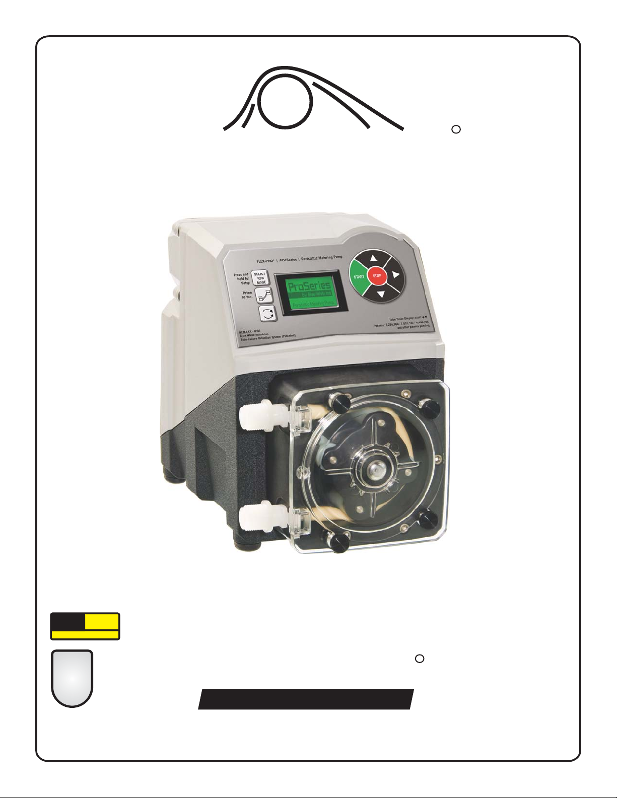
FLEX-PRO
Peristaltic Metering Pump
R
5300 Business Drive, Huntington Beach, CA 92649 USA
Phone: 714-893-8529 FAX: 714-894-9492
E mail: sales@blue-white.com | techsupport@blue-white.com URL: www.Blue-White.com
SERIES A2V
Operating Manual
ProSeries
by Blue-White Ind.
TM
system
TFD
Tube Failure Detection
Exclusive:
2
TWO-YEAR
WARRANTY
ProSeries
R
Protected by Patents: 8,418,364; 8,215,931;
7,001,153; 7,284,964; 4,496,295
and other patents pending
Patented
CERTIFIED FINAL DOCUMENT
Page 2

Page 2
Flex-Pro
TABLE OF CONTENTS
Section Heading Page
1.0 Introduction . . . . . . . . . . . . . . . . . . . . . . . . . . . . . . . . . . . . . . . . . . 3
1.1 Available Models . . . . . . . . . . . . . . . . . . . . . . . . . . . . . . . . . . . 3
2.0 Specifications . . . . . . . . . . . . . . . . . . . . . . . . . . . . . . . . . . . . . . . . 4
2.1 Materials of Construction . . . . . . . . . . . . . . . . . . . . . . . . . . . . . 4
3.0 Features . . . . . . . . . . . . . . . . . . . . . . . . . . . . . . . . . . . . . . . . . . . . 5
3.1 Agency Listings . . . . . . . . . . . . . . . . . . . . . . . . . . . . . . . . . . . . 5
4.0 Installation. . . . . . . . . . . . . . . . . . . . . . . . . . . . . . . . . . . . . . . . . . . 6
4.1 Mounting Location . . . . . . . . . . . . . . . . . . . . . . . . . . . . . . . . . . 6
4.2 Dimensions . . . . . . . . . . . . . . . . . . . . . . . . . . . . . . . . . . . . . . . 6
4.3 Installing Injection Fitting and Strainer . . . . . . . . . . . . . . . . . . . .7
5.0 Power Connections . . . . . . . . . . . . . . . . . . . . . . . . . . . . . . . . . . . . 8
5.1 Wiring Terminal and I/O Schematics . . . . . . . . . . . . . . . . . . . . . 9
6.0 How to Operate Flex-Pro - Control Pad . . . . . . . . . . . . . . . . . . . . . . 10
6.1 Mode Descriptions . . . . . . . . . . . . . . . . . . . . . . . . . . . . . . . . . . 11
7.0 Mode0 - Set Remote Start/Stop . . . . . . . . . . . . . . . . . . . . . . . . . . . 12
7.1 Mode 0 - Set TFD Sensitivity. . . . . . . . . . . . . . . . . . . . . . . . . . . 13
7.2 Mode 0 - Set FVS (flow verification system). . . . . . . . . . . . . . . . 14, 15
7.3 Mode 0 - Set 4-20mA Output. . . . . . . . . . . . . . . . . . . . . . . . . . . 16, 17
8.0 Mode 1 - Manual Operation . . . . . . . . . . . . . . . . . . . . . . . . . . . . . . 18, 19
8.1 Mode 1 - Manual Operation Screen Shots . . . . . . . . . . . . . . . . . 19
9.0 Mode 2 - 4-20mA Input Operation . . . . . . . . . . . . . . . . . . . . . . . . . . 20, 21
9.1 Mode 2 - 4-20mA Input Screen Shots . . . . . . . . . . . . . . . . . . . . 21
10.0 Mode 3 - Frequency Input (Hz) Operation . . . . . . . . . . . . . . . . . . . . 22, 23
11.0 Mode 4 - Pulse Batch (low speed pulse) Operation . . . . . . . . . . . . . 24, 25
11.1 Mode 4 - Pulse Batch Operation Screen Shots . . . . . . . . . . . . . 25
12.0 Pump Tube Timer . . . . . . . . . . . . . . . . . . . . . . . . . . . . . . . . . . . . . 26
13.0 TFD (Tube Failure Detection) . . . . . . . . . . . . . . . . . . . . . . . . . . . . . 26
14.0 Alarm Relay. . . . . . . . . . . . . . . . . . . . . . . . . . . . . . . . . . . . . . . . . . 27
15.0 Reverse Rotation . . . . . . . . . . . . . . . . . . . . . . . . . . . . . . . . . . . . . . 27
16.0 Tube Replacement. . . . . . . . . . . . . . . . . . . . . . . . . . . . . . . . . . . . . 28
16.1 Tube Removal . . . . . . . . . . . . . . . . . . . . . . . . . . . . . . . . . . . . . 28
16.2 Tube Installation. . . . . . . . . . . . . . . . . . . . . . . . . . . . . . . . . . . . 29
17.0 Pump Maintenance . . . . . . . . . . . . . . . . . . . . . . . . . . . . . . . . . . . . 30
18.0 Pump Head Replacement Parts List . . . . . . . . . . . . . . . . . . . . . . . . 31
19.0 Output Versus Fluid Viscosity . . . . . . . . . . . . . . . . . . . . . . . . . . . . . 32
Warranty . . . . . . . . . . . . . . . . . . . . . . . . . . . . . . . . . . . . . . . . . . . . 34
PLEASE READ ENTIRE INSTRUCTION MANUAL PRIOR TO INSTALLATION AND USE.
Page 3
Congratulations on purchasing Flex-Pro variable speed Peristaltic Metering Pump. A peristaltic pump is a type of
positive displacement pump used for pumping a variety of fluids.
Your Flex-Pro pump is pre-configured for tubing that shipped with your metering pump. Tubing assembly has an
Identification number printed on tube for easy re-order; such as ND, NH, etc.
Please Note: Your new pump has been pressure tested at factory with clean water before shipping. You may
notice trace amounts of clean water in pre-installed tube assembly. This is part of our stringent quality assurance
program at Blue-White Industries.
Page 3
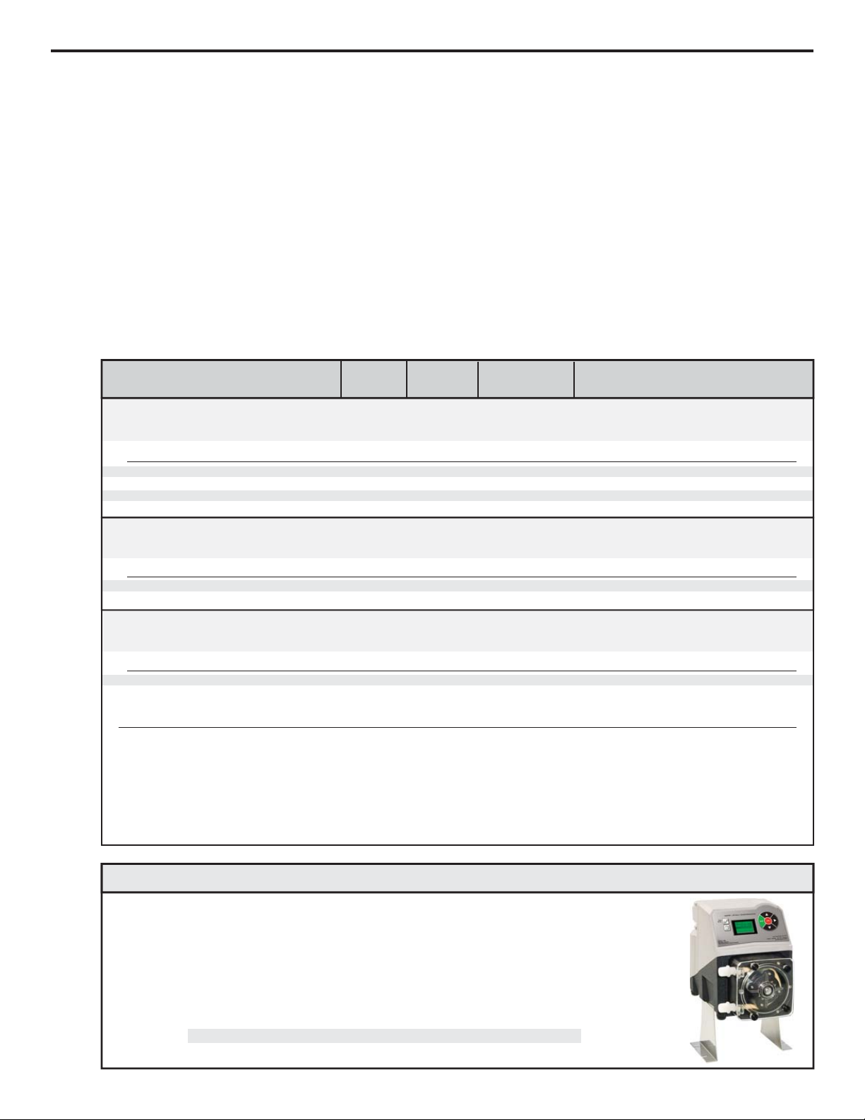
1.1 Available Models
Flex-Pro
®
Tygothane A2 Tube Pumps
Meets FDA criteria for food | Resistant to oils, greases and fuels
GPH
.04 - 4.0
.09 - 9.3
LPH
.15 - 15.2
.35 - 35.2
ML/Min
3 - 253
6 - 587
RPM
130
130
115V AC
A2V24-*GE
A2V24-*GG
230V AC
A2V25-*GE
A2V25-*GG
220V AC
A2V26-*GE
A2V26-*GG
®
Norprene Chemical A2 Tube Pumps
Meets FDA criteria for food | Superb chemical resistance
LPH
.56 - 56.2
230V AC
A2V25-*TH
115V AC
A2V24-*TH
GPH
.15 - 14.9
220V AC
A2V26-*TH
ML/Min
9 - 937
RPM
130
®
Norprene A2 Tube Pumps
Meets FDA criteria for food | Excellent chemical resistance | CIP | SIP
LPH
.52 - 52.2
.07 - 6.5
.21 - 20.6
230V AC
A2V25-*ND
A2V25-*NH
A2V25-*NF
115V AC
A2V24-*ND
A2V24-*NH
A2V24-*NF
GPH
.06 - 5.5
.14 - 13.8
.02 - 1.7
220V AC
A2V26-*ND
A2V26-*NH
A2V26-*NF
ML/Min
9 - 870
1 - 108
3 - 344
Feed Rate
RPM
130
130
130
Max
Speed
A2 Model Numbers
PSI (bar)
65 ( )
65 ( )
4.5
4.5
Max
Pressure
PSI (bar)
125 (8.6)
125 (8.6)
125 (8.6)
PSI (bar)
50 (3.4)
Max
Temperature
F (C)
185 (85)
185 (85)
185 (85)
F (C)
130 (54)
F (C)
130 (54)
130 (54)
* Inlet/outlet connection type
S = 3/8” OD x 1/4” ID tubing compressions type connections
M = ½” male NPT
C-= 3/4” tri-clamp connections
! Flex-Pro Pumps motor speed is linear over entire 1% to 100% adjustment range.
! Output versus pressure is nearly linear in all models. Larger tubes exhibit greater losses.
! For optimum tube life, specify pump to operate at lowest possible RPM and pressure.
! Feed rates taken in laboratory environment with clean water after 20 minute tube break-in period with a 3 foot (1 meter) suction lift.
n Raise metering pump 4-1/2 inches (11.43 cm) off ground or a surface.
n Made out of tough Stainless Steel.
n Provides a stable mounting surface.
Stainless Steel extended brackets allow pump to be securely mounted to most any surface; floor,
shelf, or skid. Brackets lift pump up 4-1/2 inches (11.43 cm), for easy pump access in hard to reach
areas.
Model #
72000-380
Description
Extended Mounting Bracket, 1 Pair, SS, 4 SS Screws
Optional Extended Brackets
1.0 Introduction
Page 4

2.0 Specifications
2.1 Materials of construction
Wetted components: Non-Wetted components:
Enclosure:
413 Aluminum (Polyester powder coated)
Pump Head:
q
Valox (PBT) thermoplastic
Pump Head Cover:
Clear Acrylic - Annealed for added strength and chemical
resistance.
Permanently lubricated sealed motor shaft support ball bearing.
Acrylic shaft support bearing retainer.
Cover Screws:
Stainless Steel
Roller Assembly:
q
Rotor:.................. ................Valox (PBT)
Rollers: ...............................Nylon
Roller Bearings: . ................SS Ball Bearings
Motor Shaft:
Chrome plated steel
TFD System Sensor pins:
Hastelloy C-276
Power Cord:
3 conductor, SJTW-A Water-resistant
Tube Installation Tool:
GF Nylon
Mounting Brackets and Hardware:
316 Stainless Steel
Power Cord Options:
115V60Hz = NEMA 5/15 (USA)
230V60Hz = NEMA 6/15 (USA)
220V50Hz = CEE 7/VII (EU)
240V50Hz = AS 3112 (Australia/New Zealand)
Motor:
Brushed DC, 1/8 H.P.
Duty cycle:
Continuous
Motor speed adjustment range 100:1:
1.0% - 100% motor speed (1.3 to 130 RPM)
Motor speed adjustment resolution:
0.1% increments
Display
Backlit LCD, UV resistant.
Keypad
Eight button positive action tactile switch keypad.
Enclosure:
NEMA 4X (IP66), Polyester powder coated aluminum.
Maximum Overall Dimensions:
7-1/2” W x 10-1/4” H x 14” D (19 W x 26 H x 35.6 D cm)
Approximate shipping wt:
25 lb. (12.0 Kg)
Maximum working pressure (excluding pump tubes):
125 psig (8.6 bar)
Note: see individual pump tube assembly maximum pressure
ratings.
Maximum Fluid temperature (excluding pump tubes):
oo
3/8” OD x 1/4” ID tubing connections: 130 F (54 C)
oo
M/NPT connections: 185 F (85 C)
Note: see individual pump tube assembly maximum temperature
ratings.
Maximum fluid viscosity:
12,000 Centipoise
Maximum suction lift:
30 ft. Water, 0 psig (4.5 m, 0 bar)
Ambient Operating Temperature
OOOO
14 F to 115 F (-10 C to 46 C)
Ambient Storage Temperature
OOOO
-40 F to 158 F (-40 C to 70 C)
Operating Voltage:
115VAC/60Hz, 1ph (1.5 Amp Maximum)
230VAC/60Hz, 1ph (0.7 Amp Maximum)
220VAC/50Hz, 1ph (1.0 Amp Maximum)
240VAC/50Hz, 1ph (1.0 Amp Maximum)
Pump Tube Assembly (Model Specific - 2 provided):
q q q
Tubing: . . . . . Norprene or Norprene Chemical or Tygothane
Adapter fittings: .PVDF
Injection / Back-flow Check valve:
Body & insert: ....................PVDF
Check Ball: .........................Ceramic
Spring: ................................Hastelloy C-276
q
Ball Seat O-ring:.................Viton (optional EPDM)
q
Static Seal O-ring:..............Viton (optional EPDM)
q
Duckbill anti-scale valve: Santoprene
Ancillary Items provided
With “S” tubing type connections only:
Suction Tubing: .....3/8” OD x 1/4” ID x 10’ Clear PVC
Discharge Tubing: . . . . 3/8” OD x 1/4” ID x 10’
Polyethylene
(LLDPE)
Suction Strainer: . . . . . Polypropylene
Suction Strainer:
Body:. . . . . . . . . . . PVDF
Check Ball: . . . . . . . . Ceramic
q
Ball Seat O-ring: . . . . . Viton (optional EPDM)
With “B” tubing and “M” M/NPT connections only:
Suction Strainer:
Body: .................PVDF
Check Ball: ............Ceramic
q
Ball Seat O-ring: ........Viton (optional EPDM)
With “C” Tri-clamp connections only:
none
Page 4
Flex-Pro
Page 5
3.0 Features
Peristaltic pump design does not have valves that can clog requiring maintenance.
Self priming - even against maximum line pressure. By-pass valves are not required. Cannot vapor lock or lose prime.
Backlit LCD displays motor speed, input signal values, service and alarm status.
CNC precision machined squeeze rollers and CNC machined alignment rollers for optimum squeeze, unparalleled
accuracy, and tube life.
Heavy duty rotor - single piece plastic rotor means no flexing and increased accuracy with no metal springs or hinges to
corrode.
Inject at maximum pressure in either direction (clockwise and counter clockwise).
Variable speed DC motor.
Rated for continuous duty (24X7).
Specially engineered tubing for long life at high pressures. Meets FDA 21 CFR requirements for food contact
applications.
Patented Tube Failure Detection (TFD) system. Senses tube failure by detecting chemical in pump head.
Compatible with Blue-White’s output Flow Verification Sensor (FVS) system.
Enclosure Rating:
NEMA 4X: Constructed for either indoor or outdoor use to provide a degree of protection to personnel against
incidental contact with enclosed equipment; to provide a degree of protection against falling dirt, rain, sleet,
snow, windblown dust, splashing water, and hose-directed water; and that will be undamaged by external
formation of ice on enclosure.
IP66: No ingress of dust; complete protection against contact. Water projected in powerful jets against
enclosure from any direction shall have no harmful effects.
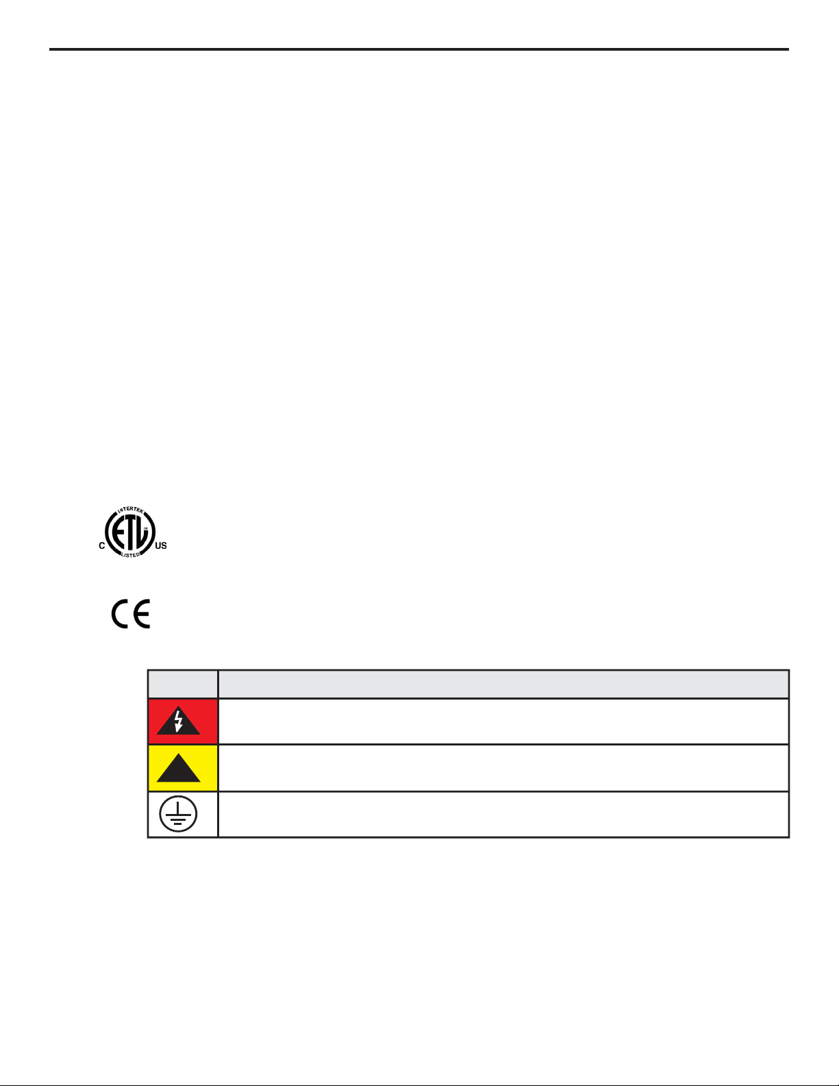
3.1 Agency Listings
Symbol Explanation
!
WARNING, risk of electric shock
CAUTION, refer to users’ guide
GROUND, PROTECTIVE CONDUCTOR TERMINAL
This pump is ETL listed to conforms to the following:
UL Standard 778 as a motor operated water pump
CSA Standard C22.2 as process control equipment
This pump complies to the Machinery Directive 98/37/EC, BS EN 60204-1, Low Voltage Directive
73/23/EC BS EN 61010-1, EMC Directive 89/336/EC, BS EN 50081-1/BS EN 50082-1.
Page 5
Flex-Pro
Page 6
Page 6
4.1 Mounting Location
Choose an area located near chemical supply tank, chemical injection point, and electrical supply. Install pump
where it can be easily serviced.
316SS Mounting brackets are included. Mount pump to a secure surface using enclosed mounting hardware.
Mount pump close to injection point. Keep inlet (suction) and outlet (discharge) tubing as short as possible.
Longer discharge tubing increases back pressure at pump head.
Important! Install a back flow prevention check valve at discharge side of pump to prevent system fluid from
flowing back through pump during tube replacement or if tube should rupture. Important!
A pressure relief valve is recommended at discharge of pump to prevent premature wear and damage to pump
tube in event discharge line becomes blocked.
Flex-Pro does not require back pressure. Keep discharge pressure as low as possible to maximize tube life.
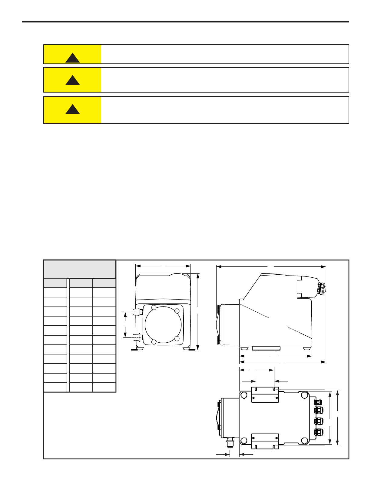
4.2 Dimensions
All diagrams are strictly for guideline purposes only. Always consult an expert before
installing metering pump on specialized systems. Metering pump should be serviced by
qualified persons only.
!
Always wear protective clothing, face shield, safety glasses and gloves when working on or
near your metering pump. Additional precautions should be taken depending on solution
being pumped. Refer to MSDS precautions from your solution supplier.
Risk of chemical overdose. Be certain pump does not overdose chemical during backwash
and periods of no flow in circulation system.
CAUTION
!
CAUTION
!
CAUTION
Flex-Pro
G
H
I
J
K
Bottom
A
F
B
E
C
D
Front Right
Inches
cm
A
B
C
D
E
10-1/4”
7-1/2”
14”
9-1/2”
11”
26
19
35.6
24.1
27.9
A2 Dimensions
F
3-3/8”
8.6
G
H
I
J
K
1-1/4”
3.2
2-1/2”
6.4
4-7/8”
12.3
7-1/4”
18.5
7-3/4”
19.7
Dim
Note: Optional Extended Bracket add 4.5” (11.43cm) to overall
height (dimension A). See page 3 for details
4.0 Installation
Page 7
Page 7
Pipe
Te e
½” male NPT
1/4” male NPT
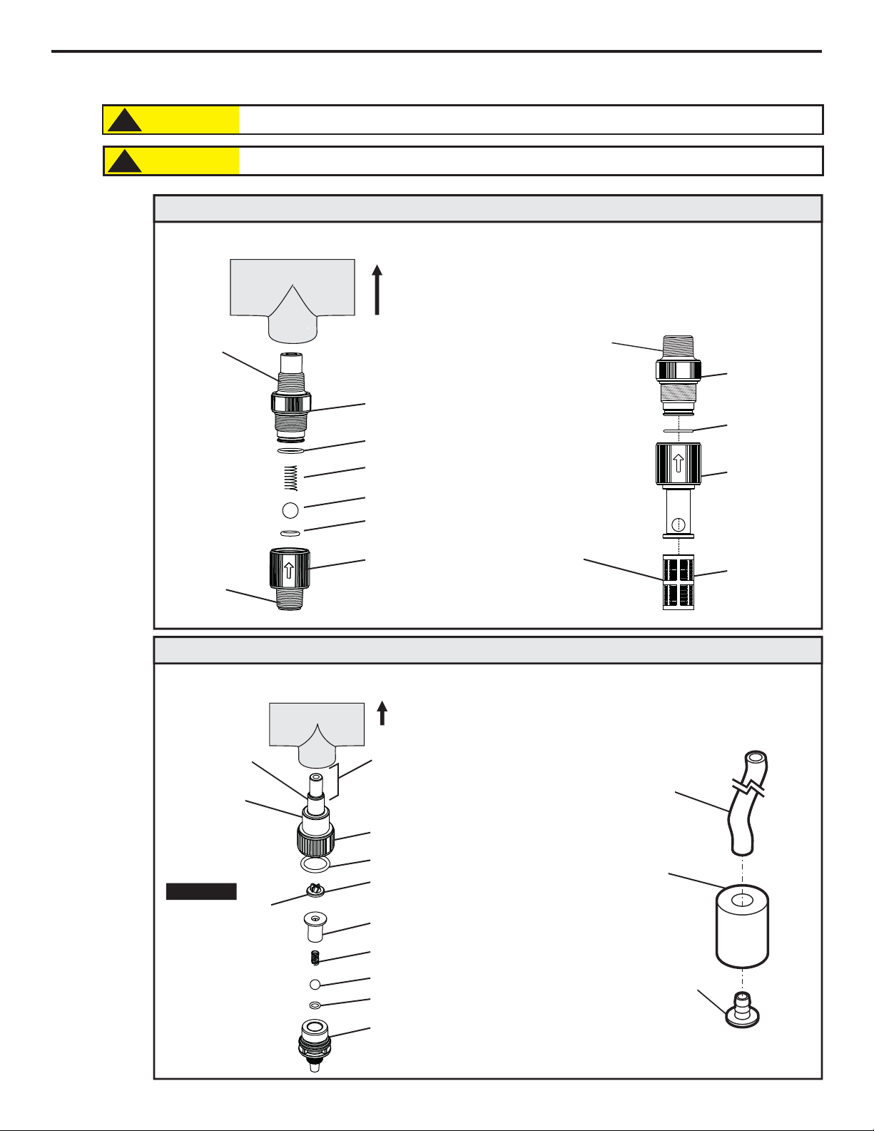
Discharge Injection Fitting / Check Valve
Discharge Injection Fitting / Check Valve)
Pipe
Te e
Install
upward
for best
results
½” (1.3 cm)
Male NPT
½” (1.3 cm)
Male NPT
or
½” (1.3 cm)
Hose Barb
Suction Strainer
Injection Fitting and Strainer for ½” (1.3cm) I.D. Connection End Models
Suction Tubing and Strainer
Weight,
Ceramic
Suction Tubing, PVC
3/8" (.95 cm) OD X
1/4” (.64 cm) ID
Strainer,
Polypropylene
Duckbill - May reduce
calcium buildup when
injecting bleach.
Duckbill will add
additional back
pressure to pump (up
to 7 psi / .48 bar).
Remove duckbill to
reduce pressure or
when metering viscous
fluids.
Proper eye and skin protection must be worn when installing and servicing pump.
!
CAUTION
This Pump Has Been Evaluated for Use with Water Only.
!
CAUTION
PVDF
PVDF
O-Ring, Viton (optional EP)
O-Ring, T/FEP
(optional EP)
Spring, Hastelloy C-276
Ball, Ceramic
½” (1.3 cm)
Male NPT
or
½” (1.3cm)
Hose Barb
PVDF
PVDF
O-Ring, Viton
(optional EP)
Polypropylene
Removable
275 Micron
Filter
PVDF
Spring, Hastelloy C-276
PVDF
O-Ring, T/FEP (optional EP)
Ball, Ceramic
O-Ring, Viton (optional EP)
Duckbill, Santoprene
(optional)
PVDF
Flex-Pro
Injection Nose
may be trimmed
(removed) when
injecting into
small pipe.
Install upward
for best results
Injection Fitting and Strainer for 1/4” (.64cm) I.D. Connection End Models
4.3 Installing Injection Fitting and Strainer
Important!
Page 8
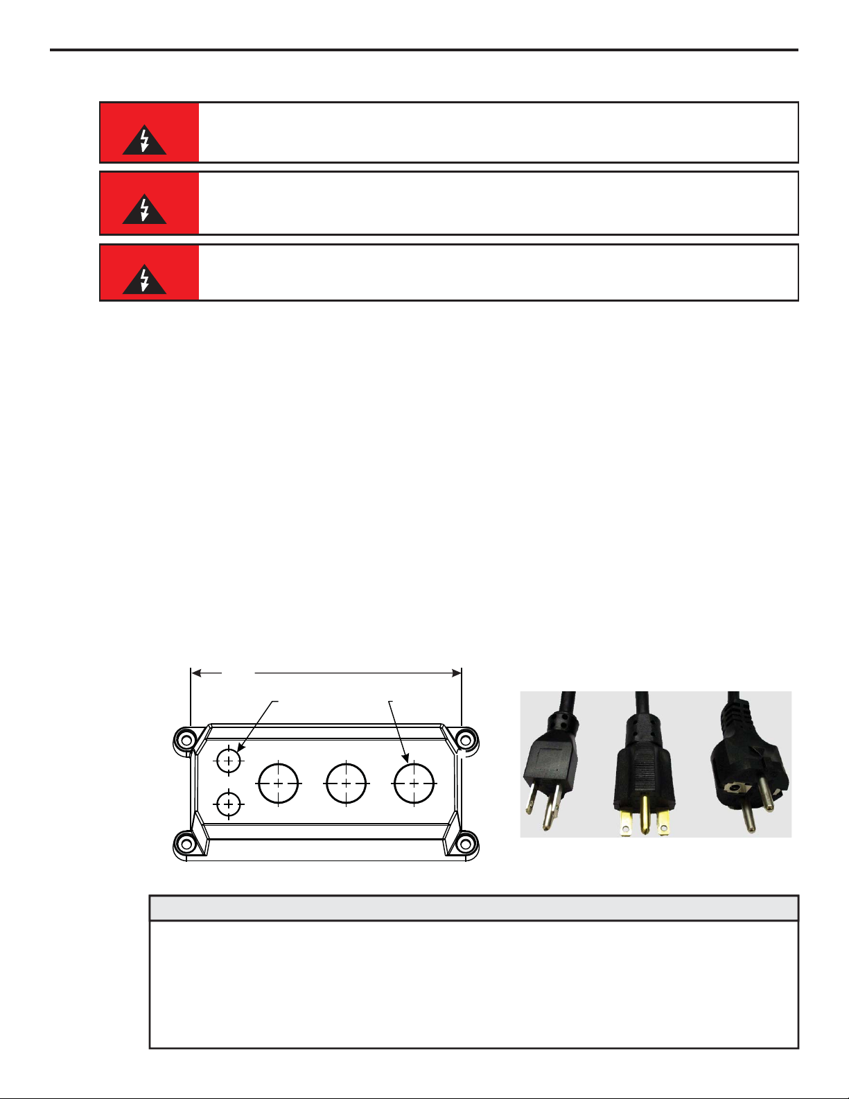
Risk of electric shock – cord connected models are supplied with a grounding
conductor and grounding-type attachment plug. To reduce risk of electric shock, be
certain that it is connected only to a properly grounded, grounding-type receptacle.
Three power cord plug types available.
Power cord length is 6 feet (3.83 meters)
WARNING
Be certain to connect pump to proper supply voltage. Using incorrect voltage will damage pump and may result in
injury. Voltage requirement is printed on pump serial label.
Input power: 115VAC 50/60 Hz 1.5 amp or 230/240VAC 50/60 Hz 0.7 amp.
Power switch located in Junction Box.
Use voltage your power cord is rated for.
Cord connected models are supplied with a ground wire conductor and a grounding type attachment plug (power
cord). To reduce risk of electric shock, be certain that power cord is connected only to a properly grounded,
grounding type receptacle.
Permanently connected models must be properly grounded. Be certain that a grounding conductor is connected
to terminal T11-1 located in wiring compartment.
Never strap control (input / output) cables and power cables together.
Power Interruption: This pump has an auto-restart feature which will restore pump to operating state it was in
when power was lost.
Note: When in doubt regarding your electrical installation, contact a licensed electrician.
Electrical connections and grounding (earthing) must conform to local wiring codes. Be
certain that a grounding conductor is connected to terminal T11-1 located in wiring
compartment.
WARNING
115V 60Hz
NEMA 5/15 (USA)
max: 125V AC
230V 60Hz
NEMA 6/15 (USA)
max: 250V AC
240V 50Hz
CEE 7/VII (EU)
max: 250V AC
6 in.
(152 mm)
Ø
(12.7 mm)
2-PLCS.
.50
Ø
(21.3 mm)
3-PLCS.
.84 in.
WIRING COMPARTMENT COVER
POWER CORD OPTIONS
Risk of electric shock - Disconnect electricity before removing wiring compartment
cover.
WARNING
Qty: 2 - .50 Inch (12.7 Mm) Liq-tight Hole Plugs (mat’l = Neoprene), Pre-installed
Qty: 3 - .875 Inch (22.2 Mm) Liq-tight Hole Plugs (mat’l = Neoprene), 2 Pre-installed
Qty: 2 - .50 Inch (12.7 Mm) Liq-tight Connectors For Pass Thru Cords (mat’l = Nylon)
Acceptable Cable Diameter .12 To .26 Inch (3.0 To 6.5 Mm), Not Installed
Qty: 3 - .875 Inch (22.2 Mm) Liq-tight Connectors For Pass Thru Cords (mat’l = Nylon)
Acceptable Cable Diameter .20 To .40 Inch (5.1 To =10.0 Mm), 1 Pre-installed W/ Power Cord Models
Qty: 2 - Metallic Liq-tight Connectors For .50 Inch Flexible Conduit (mat’l = Die Cast Zinc), Not Installed
QTY.
DESCRIPTION
Included cable and conduit connectors:
Page 8
Flex-Pro
5.0 Power Connections
Page 9
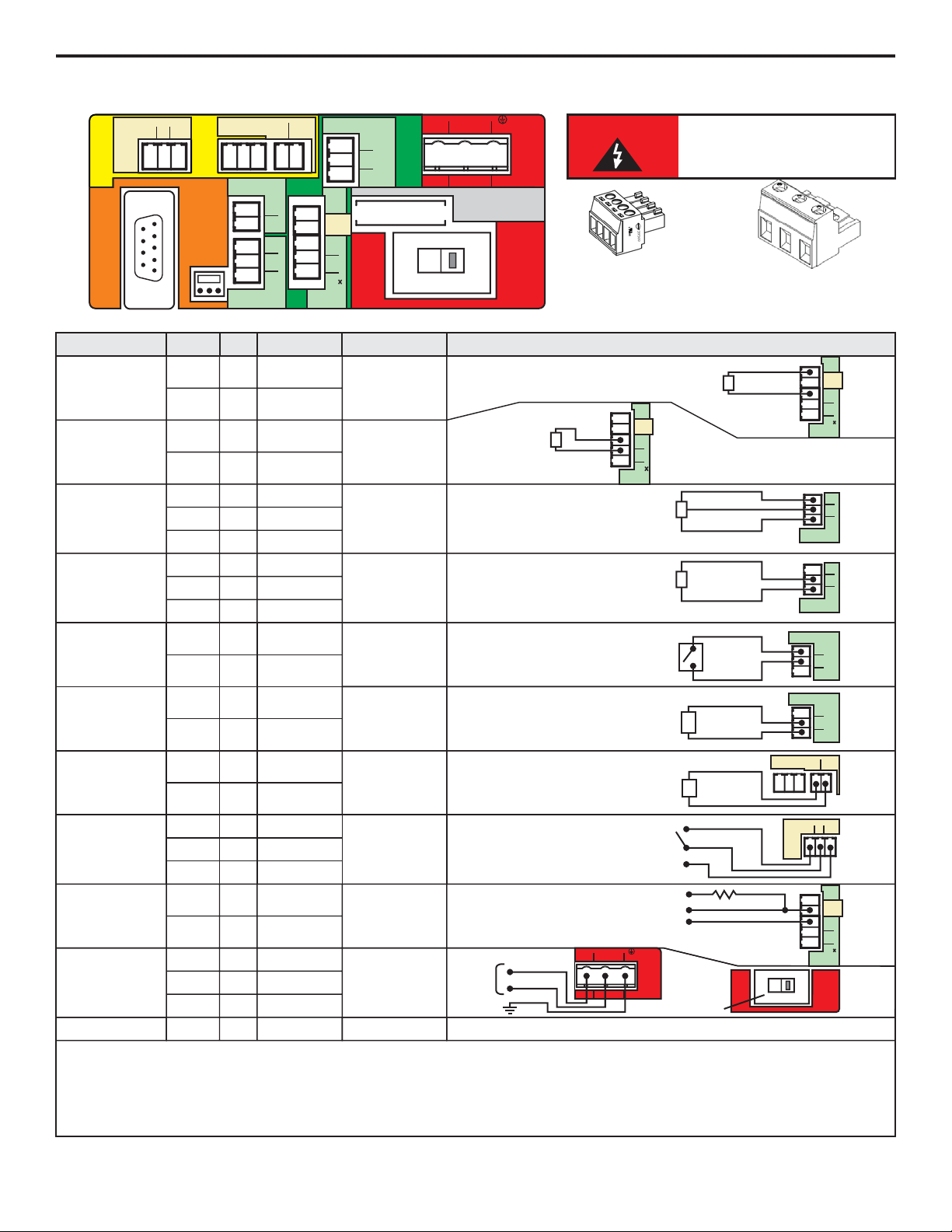
WARNING
T1
1
3
PLS
4
4-20 (+)
2
Motor
Active
(-)
5
+
-
ACTIVE 4-20mA
TRANSMITTER
SOURCE
GND (-)
4-20(+)
INPUT:
4-20 mA
INPUT:
FREQUENCY, AC
SINE WAVE, TTL,
CMOS
FUNCTION
TERM PIN # RATING ELECTRICAL SP.
BLOCK DIAGRAM
T1
T1
T1
T1
T4
T4
T4
1
3
3
4
3
4
5
(+) POSITIVE
SIGNAL
(-) NEGATIVE
OUTPUT:
4-20 mA
OUTPUT:
RELAY, 3 AMP
OUTPUT:
OPEN COLLECTOR
MOTOR ACTIVE
T6
T6
2
1
(+) POSITIVE
(-) NEGATIVE
T7
1
T7
T7
2
3
120 OHM
IMPEDANCE, NON
POWERED LOOP
6 TO 30 VOLT DC
1 AMP MAX.
120 OHM
RESISTANCE
ACTIVE LOOP
Form C
3 AMP MAX AT
250 VAC,
3 AMP MAX AT
30 VOLT DC
0-1000 HZ MAX.
NO VOLTAGE
(+)
(-)
NO
C
NC
SWITCH LOAD
3 AMP MAX @ 250V AC
3 AMP MAX @ 30V DC
EXTERNAL DEVICE
6 TO 30V DC
OPEN CIRCUIT
IMPEDANCE MUST
BE GREATER THAN
50K OHM
4-20mA RECEIVER
600 OHM LOAD MAX.
(+)
(-)
Risk of electric shock - All
wiring must be insulated
and rated 300V minimum.
Terminals T1 Thru T8
Plug type
16 - 24 AWG
Power Input Terminal T11
Plug type
14 - 30 AWG
Single or dual pump (series) input.
Loop voltage must not exceed 24 Volts.
Page 9
Flex-Pro
5.1 Wiring Terminals and I/O Schematics
115V
FUSE 5A SLOW
BLOW (20 X 5MM)
POWER
T11
GROUND
N EUTRAL
(COMMON)
LINE
(HOT)
1
23
S1
OUTPUT
INPUT
P1
TO COM
BOARD
T7
RELAY
OUT
T3
REMOTE
I N
T2
T4
T1
FVS
3
1
2
DRY
RMT
COM
4-20mA
1
2
3
N.C.
COM
N.O.
1
2
(-)
(+)
1
3
PLS
4
4-20 (+)
1
2
(-)
(+)
3
4
5
(+)
(-)
SIG
DIR
T6
RS-232
T12
POWER
F1
2
Motor
Active
(-)
5
T1
1
3
PLS
4
4-20 (+)
2
Motor
Active
(-)
5
+
-
FREQUENCY
TRANSMITTER
SOURCE
GND (-)
PULSE
T4
FVS
3
4
5
(+)
(-)
SIG
BLUE-WHITE
FVS SENSOR
GND (-)
SIGNAL
PWR (+)
RED (+)
BLACK (-)
BARE
T3
REMOTE
I N
3
1
2
DRY
RMT
COM
T3
T3
1
2
(+) POSITIVE
(-) NEGATIVE
T3
T3
2
3
(+) POSITIVE
(-) NEGATIVE
T3
REMOTE
I N
3
1
2
DRY
RMT
COM
T4
T4
4
5
SIGNAL
(-) NEGATIVE
T4
FVS
3
4
5
(+)
(-)
SIG
BLUE-WHITE
MICRO-FLO
FLOWMETER
PULSE OUTPUT
GND (-)
SIGNAL
PWR (+)
NEGATIVE (-)
SIGNAL
1
2
(-)
(+)
T6
T7
RELAY
OUT
1
2
3
N.C.
COM
N.O.
(-)
(+)
T1
1
3
PLS
4
4-20 (+)
2
Motor
Active
(-)
5
GND (-)
T1
T1
2
3
CLOSED WHILE MOTOR
IS ENERGIZED
NEGATIVE (-)
SIGNAL OUT
4.7K OHM
MOTOR
ACTIVE
5 TO 24 VDC
INPUT:
POWER
T11
1
T11
T11
2
3
T11
GROUND
N EUTRAL
(COMMON)
LINE
(HOT)
1
23
POWER
AC
VOLTAGE
115V OR 230V AC
MANUAL SWITCH
50 / 60 HZ
100W
GROUND
NEUTRAL
LINE (HOT)
115V
POWER
S1
POWER
VOLTAGE
SWITCH
SWITCH
FROM
115V TO 230V
FUSE F1 N/A 5 AMP
5A SLOW BLOW
(20 X 5MM)
(+) POSITIVE
(-) NEGATIVE
(-) NEGATIVE
(+) POSITIVE
INPUT:
FVS SYSTEM
(FLOW VERIFICATION
SENSOR)
FS or FP MICRO-FLO
FLOW METER ONLY
INPUT:
FVS SYSTEM
(FLOW VERIFICATION
SENSOR)
FV SENSOR ONLY
INPUT:
REMOTE
START / STOP
(DRY CONTACT C.)
INPUT:
REMOTE
START / STOP
(WET CONTACT C.)
NORM. CLOSED
NORM. OPEN
COMMON
4-20
COMMON
SIGNAL
Page 10
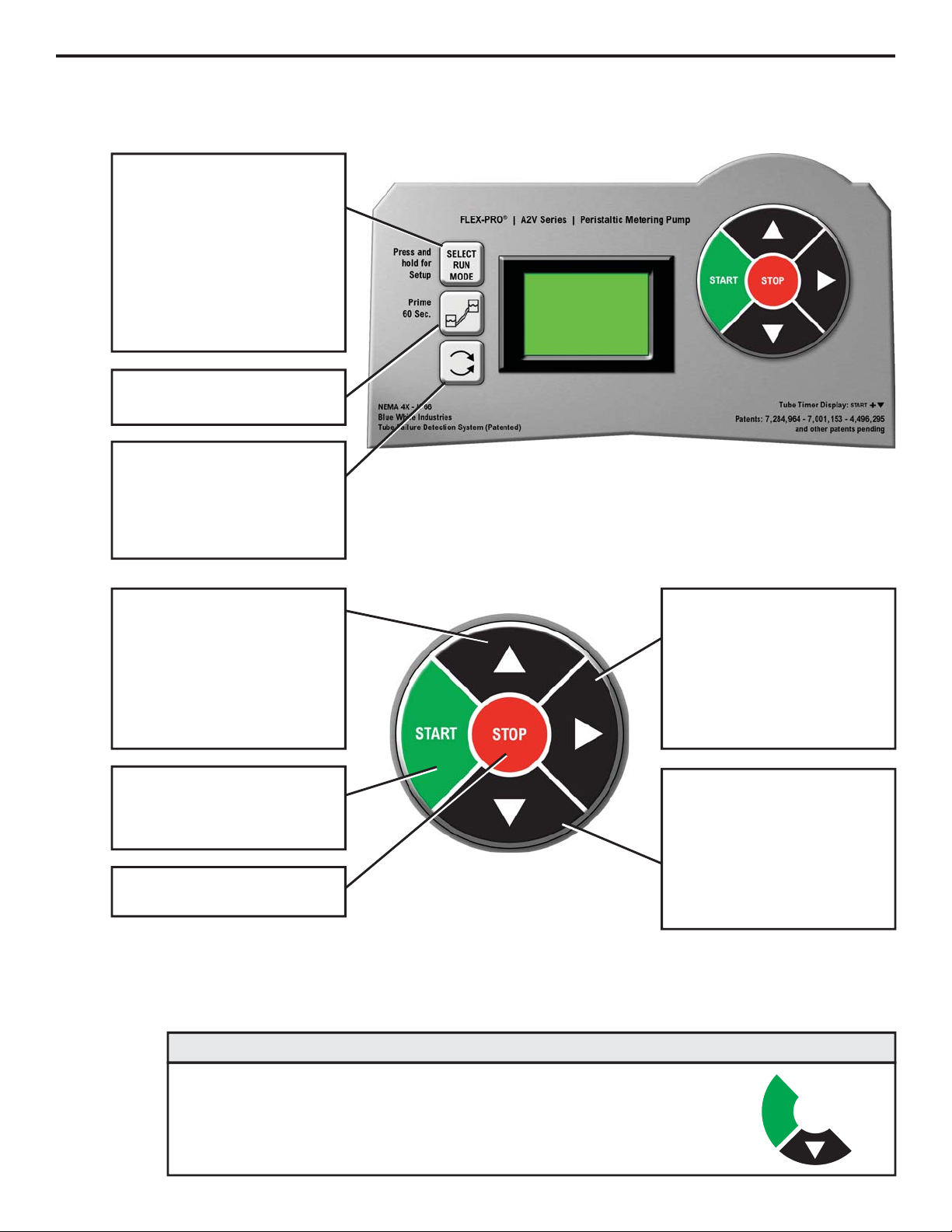
Press and release
To select Run Mode
Mode 1: Manual
Mode 2: 4-20mA input
Mode 3: Frequency input
Mode 4: Pulse / Batch
Press and Hold
To configure selected Mode
Mode 0: Setup
Mode 1: Manual
Mode 2: 4-20mA input
Mode 3: Frequency input
Mode 4: Pulse / Batch
Press and release
To prime pump (60 seconds)
Press and hold
To change rotor direction
clockwise or counterclockwise
Important: Hold button down to
trigger rotor reversal
Press and release
To
in Setup mode.
To increase value while in
programming mode.
Press UP arrow to increase
pump speed (output) in Manual
mode (Mode 1).
scroll through menu options
Press and release
To Start pump.
To begin listening (reacting) to
external signals.
Press and release
To Stop pump.
Press and release
To
in Setup mode.
To scroll through pump speed
(output) and current incoming
signals in run modes:
Mode 2, Mode 3, & Mode 4
scroll through menu options
Press and release
To
in Setup mode.
To decrease value while in
programming mode.
Press DOWN arrow to
decrease pump speed (output)
in Manual mode (Mode 1).
scroll through menu options
To view amount of run time hours on currently installed tube.
START + DOWN arrow displays current pump tube timer.
Hold down START button, then press and release DOWN arrow.
Tube Life Timer
Page 10
Flex-Pro
6.0 How to Operate Flex-Pro - Control Pad
START
Page 11
Mode 0 - Setup
Press and Hold to configure:
ŸRemote Start / Stop
ŸTFD (Tube Failure Detection) sensitivity
ŸFVS (Flow Verification Sensor) time delay - requires sensor
Ÿ4-20 mA output, available on certain models
Mode 0
Mode 1 - Manual
Run pump locally by selecting pump speed (1 - 100%).
ŸControl speed by using up or down arrows after start button is
pressed.
ŸControl speed by entering Mode 1 setup and selecting desired
pump speed (1 - 100%)
Mode 2 - 4-20 mA Input Signal
Run pump remotely via external 4-20 mA signal.
ŸPress and Hold “Select Run Mode” button with Mode 2
selected to configure settings.
ŸSelect Mode 2 and press START button to allow pump to be
controlled by external 4-20mA signal.
Mode 3 - Frequency (Hz) Input Signal
Run pump remotely via external high frequency (Hz) signal.
ŸPress and Hold “Select Run Mode” button with Mode 3
selected to configure settings.
ŸSelect Mode 3 and press START button to allow pump to be
controlled by external frequency (Hz) signal.
Mode 4 - Pulse Batch Input Signal (low speed pulse)
Run pump remotely via external low speed pulse signal.
Ÿ Press and Hold “Select Run Mode” button with Mode 4
selected to configure settings.
Ÿ Select Mode 4 and press START button to allow pump to be
controlled by external low speed pulse signal.
SEt
0
Mode 1
OFF
1
Mode 2
OFF
2
Mode 3
OFF
3
Mode 4
OFF
4
Page 11
Flex-Pro
SPEED
mA
Hz
Hz
ON
6.1 Mode Descriptions
Page 12

Page 12
Flex-Pro
Used to remotely start and stop pump using a dry contact closure signal.
When activated; CLOSE = START and OPEN = STOP.
Set to NO = Remote Start / Stop is disabled
Set to Yes = Remote Start / Stop is enabled
Can be used with external foot pedal, PLC, contact closure or other similar external devices.
Default setting = No (disabled)
Step 1
Press and release STOP button
Note: Mode cannot be changed while pump is in running.
Press and release SELECT RUN MODE button multiple
times until Mode 0 is selected.
Step 2
With Mode 0 selected, press and hold SELECT RUN MODE
button until ‘Remote’ icon begins flashing.
Default setting ‘NO’ will also be visible when entering
remote start / stop setup.
Note: If ‘YES’ had been selected previously, then ‘YES’ will be
displayed on screen.
Step 3
Press and release DOWN arrow to change setting to ‘YES.’
To change setting back to ‘NO’ press and release UP arrow.
Step 4
After you’ve made your selection, press and release RIGHT
arrow button. This saves your setting.
You can now modify other settings in Mode 0 or you can exit
Setup by pressing and holding SELECT RUN MODE button
for a few seconds until you return to Run screen.
Running pump with Remote Start / Stop enabled, ‘REMOTE’ icon will always be visible on lower left side of screen.
Pump will display ‘STBY’ (standby) if pump is in stop mode via contact closure signal. Please use caution in this mode, pump can
start at anytime. If you must perform maintenance to pump, press and release STOP button.
Mode 0
SEt
0
Mode 0
no
0
Remote
Icon
Mode 0
yes
0
Mode 0
yes
0
REMOTE
REMOTE
REMOTE
7.0 Mode 0 - Set Remote Start / Stop
Page 13

Page 13
Flex-Pro
Flex-Pro pump is equipped with a Tube Failure Detection (TFD) system which is designed to stop pump in event
pump tube should rupture and chemical enters pump head. This patented system is capable of detection presence of a large number of chemicals including Sodium Hypochlorite (chlorine), Hydrochloric (muriatic) Acid,
Sodium Hydroxide, and many others.
Minimum and Maximum setting = 75 % to 100%
Default Setting = 75%
(75% is recommended; triggers with most water treatment chemicals without false alarms)
Important: 100% sensitivity setting may trigger false alarm by washdown or rain. 100% setting is only recommended
when absolutely necessary.
Confirm chemical detection - To determine if your chemical will be detected by system, remove pump tube and rotor. Place a small
amount of chemical in bottom of pump head - just enough to cover sensors. Turn on pump. If TFD system detects chemical, pump will
stop after two seconds and TFD alarm screen will display. Press STOP button to clear alarm.
Step 1
Press and release STOP button
Note: Mode cannot be changed while pump is in running.
Press and release SELECT RUN MODE button multiple
times until Mode 0 is selected.
Step 3
Step 4
TFD icon will appear for 1 second, followed by numbers.
Numbers indicate sensitivity value of TFD.
Press and release UP arrow button to increase sensitivity
value.
Press and release DOWN arrow button to decrease
sensitivity value.
Step 5
After you’ve made your selection, press and release RIGHT
arrow button. This saves your setting.
You can now modify other settings in Mode 0 or you can exit
Setup by; press and hold SELECT RUN MODE button for a
few seconds until you return to Run screen.
Mode 0
SEt
0
Mode 0
tfd
0
Mode 0
75.0
0
Mode 0
set
0
Step 2
With Mode 0 selected, press and hold SELECT RUN MODE
button until ‘Remote’ icon begins flashing.
This indicates that you’ve entered Setup menu.
Mode 0
no
0
Remote
Icon
Press and release RIGHT arrow button to scroll through
menu until you see TFD icon.
If you pass TFD screen, continue to press and release
RIGHT arrow button until TFD icon appears.
REMOTE
7.1 Mode 0 - Set TFD Sensitivity
Page 14

Page 14
Flex-Pro
Flow verification sensor sold separately.
Flow verification system is designed to stop pump in an event sensor does not detect flow during pump operation.
Indicating an empty chemical tank, clogged injection fitting, loose tubing connection, etc.
To allow pump to clear any gasses that may have accumulated over time, an alarm delay time value from 1 to 255
seconds must be programmed.
Note: An alarm delay of 000 seconds disables FVS system.
Step 1
Press and release STOP button
Note: Mode cannot be changed while pump is in running.
Press and release SELECT RUN MODE button multiple
times until Mode 0 is selected.
Step 2
With Mode 0 selected, press and hold SELECT RUN MODE
button until ‘Remote’ icon begins flashing.
This indicates that you’ve entered Setup menu.
Step 3
Press and release RIGHT arrow to scroll through menu until
you see FVS icon.
If you pass FVS screen, continue to press and release
RIGHT arrow button until FVS icon appears.
Step 4
FVS icon will appear for 1 second, followed by numbers.
These numbers indicate delay time setting for FVS.
Select a delay time in seconds. Delay time is amount of time
pump will wait to receive a pulse from sensor until an alarm
it triggered.
A delay time of 00 deactivates FVS feature.
Mode 0
SEt
0
Mode 0
FVS
0
Mode 0
no
0
Remote
Icon
Mode 0
00
0
Step 5
After you’ve made your selection, press and release RIGHT
arrow button. This saves your setting.
You can now modify other settings in Mode 0 or you can exit
Setup by; press and hold SELECT RUN MODE button for a
few seconds until you return to Run screen.
Mode 0
set
0
REMOTE
SEC
7.2 Mode 0 - Set FVS (flow verification system)
Time-out - Flex-Pro pumps have a time-out setting of 20 seconds while in configuration menus. If built-in timer exceeds 20 seconds
without a button being pressed, then pump will exit configuration menu. Changes will only be saved after RIGHT arrow button is
pressed and released.
Page 15

Page 15
Flex-Pro
Flow Verification Sensor is designed to give you two installation options.
Sensor can be installed:
!
Directly on pumphead of A2 pump, suction side.
!
Anywhere on suction side of A2 pump.
Wiring for sensor can be connected directly to an A2 pump. Pump will stop pumping if sensor detects no flow. A
relay will then close allowing for remote alarm indication or initiation of a back-up injector pump. Install FVS Flow
Sensor - Flow Verification Sensor should be installed on inlet (suction) side of pump tube. Sensor includes a PVC
tubing insert, located inside sensors female thread connection, that is designed to seal sensor onto pump tube
inlet adapter. Thread sensor onto pump tube until tubing insert is snug against pump tube inlet fitting - do not
over-tighten.
7.2 Mode 0 - Set FVS (flow verification system) - Continued
Sensor Model Number
Actual Working Range with
Flex-Pro Pump
ML/Min
ML/Min
30-200
FV-100 30-300
Published Flow Range
50-900
FV-200 100-1000
100-1800
FV-300 200-2000
300-3000
FV-400 300-3000
500-5000
FV-500 500-5000
700-7000
FV-600 700-7000
Confirm FVS flow range - Flow Verification Sensor (FVS) will only function
within its operating range. See chart for available ranges.
Example: Sensor model FV-100 has an operation range of 30-300 ml/min
when used as a flowmeter. However, due to pressure drop across sensor,
pump’s suction capability is limited to 14.7 psi. When used as a Flow
Verification Sensor with a peristaltic pump, effective operating range is
reduced to 30-200 ml/min.
NOTE: If pump output is less than 30 ml/min, sensor will not detect chemical
and a signal will not be sent to pump, resulting in an alarm condition.
NOTE: For low viscosity (water-like) fluids only. Consult factory if attempting
to use with viscous fluids.
Page 16

Page 16
Flex-Pro
Available on certain models.
Sends a configurable 4-20 mA signal, based on pump rotor speed, to an external device. This feature can be
used to control other pumps (in sync / proportionally), data logging systems, and other external devices for plant
automation.
Default setting: Minimum Speed = 4 mA signal output
Maximum Speed = 20 mA signal output
Set to NO = disabled
Set to Yes = enabled
Time-out - Flex-Pro pumps have a time-out setting of 20 seconds while in configuration menus. If built-in timer exceeds 20 seconds
without a button being pressed, then pump will exit configuration menu. Changes will only be saved after RIGHT arrow button is
pressed and released.
Step 1
Press and release STOP button
Note: Mode cannot be changed while pump is in running.
Press and release SELECT RUN MODE button multiple
times until Mode 0 is selected.
Step 2
With Mode 0 selected, press and hold SELECT RUN MODE
button until ‘Remote’ icon begins flashing.
This indicates that you’ve entered Setup menu.
Step 3
Press and release RIGHT arrow to scroll through menu until
you see 4-20 mA icon.
To select Yes, press and release DOWN arrow.
To select No, press and release UP arrow.
To begin configuring values, select Yes.
Then press and release RIGHT arrow.
Step 4
Minimum pump speed will be displayed.
To increase value, press and release UP arrow.
To decrease value, press and release DOWN arrow.
To save value, press and release RIGHT arrow.
Mode 0
SEt
0
yes
0
Mode 0
no
0
REMOTE
Remote
Icon
Mode 0
MAOUT
4-20 mA Icon
Mode 0
6
4
8
10
12
14
16
18
20
0
25
50
75
100
Pump Motor Speed (%)
Milliamp Output (mA) Signal
Default Setting
0.1
0
MAOUT
4-20 mA Icon
SPEED
MIN
7.3 Mode 0 - Set 4-20mA Output
Page 17

Page 17
Flex-Pro
Step 8
You can now modify other settings in Mode 0 or you can exit
Setup by; press and hold SELECT RUN MODE button for a
few seconds until you return to Run screen.
Mode 0
set
0
Step 5
Output signal at minimum speed will now be displayed.
To increase value, press and release UP arrow.
To decrease value, press and release DOWN arrow.
To save value, press and release RIGHT arrow.
4
MAOUT
4-20 mA Icon
MIN
Step 6
Maximum pump speed will be displayed.
To increase value, press and release UP arrow.
To decrease value, press and release DOWN arrow.
To save value, press and release RIGHT arrow.
Mode 0
100.0
0
MAOUT
4-20 mA Icon
SPEED
Step 7
Output signal at maximum speed will now be displayed.
To increase value, press and release UP arrow.
To decrease value, press and release DOWN arrow.
To save value, press and release RIGHT arrow.
20.0
MAOUT
4-20 mA Icon
Mode 0
0
Example 1
6
4
8
10
12
14
16
18
20
0
25
50
75
100
Pump Motor Speed (%)
Milliamp Output (mA)
Signal
0% Pump Output = 4 mA
100 % Pump Output = 20 mA
Example 2
6
4
8
10
12
14
16
18
20
0
25
50
75
100
Pump Motor Speed (%)
Milliamp Output (mA)
Signal
0% Pump Output = 4 mA
50% Pump Output = 16 mA
7.3 Mode 0 - Set 4-20mA Output - Continued
Page 18

Page 18
Flex-Pro
Used to manually control speed of pump.
Use UP and DOWN arrows to adjust speed while pump is running.
To select exact run speed, follow steps below.
Step 1
Press and release STOP button
Note: Mode cannot be changed while pump is in running.
Press and release SELECT RUN MODE button multiple
times until Mode 1 is selected.
Step 2
With Mode 1 selected, press and hold SELECT RUN MODE
button until ‘Speed’ icon begins flashing.
This indicates that you’ve entered Setup menu.
Step 4
Pump will now operate at your pre-configured speed.
Press and release START button to start pump.
Press and release STOP button at anytime to stop pump.
With pump operating in manual mode (Mode 1), pump speed can be changed at anytime by using UP or DOWN arrows during
operation.
Mode 1
50.0
1
Mode 1
OFF
SPEED
1
SPEED
Step 3
Current pump speed will be displayed.
To increase value, press and release UP arrow.
To decrease value, press and release DOWN arrow.
To save value, press and hold SELECT RUN MODE button
until ‘Speed’ icon stop flashing.
Mode 1
50.0
1
SPEED
Mode 1
OFF
1
SPEED
8.0 Mode 1 - Manual Operation
Page 19

Page 19
Flex-Pro
8.1 Mode 1 - Manual Operation Screen Shots
Runtime Screen Shot 1
Display motor speed percentage.
Pump Running in Manual Operation
Runtime Screen Shot 2
Display 4-20mA output (select models only)
Press and release RIGHT arrow to view mA output value
in real-time.
Please note: 4-20mA output is only available on select models. If included in
your model; 4-20mA output must be enabled in Mode 0 (see page 16).
9.6
mA
1
35.0
1
SPEED
OUT
Runtime Screen Shot 3
Display motor speed percentage.
Press and release RIGHT arrow to view percentage of
motor speed.
35.0
1
SPEED
Runtime Screen Shot 4
Display tube life timer.
Press and hold START button.
Press and release DOWN arrow.
Displays amount of total runtime hours on currently installed tube.
Time will be displayed in hours.
Timer will be display for approximately 5 seconds before returning to
previous runtime screen.
236
1
SPEED
START
Hours
Page 20

Page 20
Flex-Pro
Used to remotely control pump with an incoming 4-20 mA signal.
Default setting: 4 mA signal = 0.1% motor speed
20 mA signal = 100.0% motor speed
Time-out - Flex-Pro pumps have a time-out setting of 20 seconds while in configuration menus. If built-in timer exceeds 20 seconds
without a button being pressed, then pump will exit configuration menu. Changes will only be saved after RIGHT arrow button is
pressed and released.
Step 1
Press and release STOP button
Note: Mode cannot be changed while pump is in running.
Press and release SELECT RUN MODE button multiple
times until Mode 2 is selected.
Step 2
With Mode 2 selected, press and hold SELECT RUN MODE
button until ‘Speed’ icon begins flashing.
This indicates that you’ve entered Setup menu.
Step 3
Minimum pump speed will be displayed.
To increase value, press and release UP arrow.
To decrease value, press and release DOWN arrow.
To save value, press and release RIGHT arrow.
Step 5
Maximum pump speed will be displayed.
To increase value, press and release UP arrow.
To decrease value, press and release DOWN arrow.
To save value, press and release RIGHT arrow.
Mode 2
6
4
8
10
12
14
16
18
20
0
25
50
75
100
Pump Motor Speed (%)
Milliamp Output (mA) Signal
Default Setting
2
SPEED
Mode 2
0.1
Mode 2
OFF
mA
MIN
2
SPEED
2
100.0
Step 4
mA value linked to minimum pump speed will be
displayed.
To increase value, press and release UP arrow.
To decrease value, press and release DOWN arrow.
To save value, press and release RIGHT arrow.
2
MA
Mode 2
4.0
MIN
Mode 2
0.1
MIN
2
SPEED
9.0 Mode 2 - 4-20mA Input Operation
Page 21

Page 21
Flex-Pro
Step 7
To exit Setup, press and hold SELECT RUN MODE button
for a few seconds until you return to Run screen.
Step 6
mA value linked to minimum pump speed will now be
displayed.
To increase value, press and release UP arrow.
To decrease value, press and release DOWN arrow.
To save value, press and release RIGHT arrow.
20
MA
2
Mode 2
Mode 2
OFF
mA
2
Example 1
6
4
8
10
12
14
16
18
20
0
25
50
75
100
Pump
Motor Speed (%)
Milliamp input (mA)
from external source
4 mA = 0% Pump Output
20 mA = 100% Pump Output
Example 2
6
4
8
10
12
14
16
18
20
0
25
50
75
100
4 mA = 100% Pump Output
20 mA = 0% Pump Output
Example 3
6
4
8
10
12
14
16
18
20
0
25
50
75
100
4 mA = 20% Pump Output
16 mA = 43.8% Pump Output
0%
Output
Pump
Motor Speed (%)
Pump
Motor Speed (%)
100%
Output
100%
Output
0%
Output
43.8%
Output
20%
Output
Milliamp input (mA)
from external source
Milliamp input (mA)
from external source
Runtime Screen Shot 1
Mode 2
9.1 Mode 2 - 4-20mA Input Screen Shots
Runtime Screen Shot 2
Mode 2
9.6
mA
2
9.0 Mode 2 - 4-20mA Input - ContinuedOperation
Display motor speed percentage.
Pump Running in 4-20mA Input Operation
Display current 4-20mA input signal
Press and release RIGHT arrow to view mA input value
in real-time.
35.0
SPEED
2
Runtime Screen Shot 3
Mode 2
9.6
mA
2
Press and release RIGHT arrow again to view mA output
value in real-time (available on select models only).
Press and release RIGHT arrow again to view motor
speed percentage, as in Screen Shot 1.
OUT
Page 22

Page 22
Flex-Pro
Used to remotely control pump with an incoming high speed frequency signal. Typically used with flow meters or
other external devices.
Default setting: 0 Frequency (Hz) = 0% motor speed
1000 Frequency (Hz) = 100% motor speed
Time-out - Flex-Pro pumps have a time-out setting of 20 seconds while in configuration menus. If built-in timer exceeds 20 seconds
without a button being pressed, then pump will exit configuration menu. Changes will only be saved after RIGHT arrow button is
pressed and released.
Step 1
Press and release STOP button
Note: Mode cannot be changed while pump is in running.
Press and release SELECT RUN MODE button multiple
times until Mode 3 is selected.
Step 2
With Mode 3 selected, press and hold SELECT RUN MODE
button until ‘Speed’ icon begins flashing.
This indicates that you’ve entered Setup menu.
Step 3
Pump speed at minimum Frequency will be displayed.
To increase value, press and release UP arrow.
To decrease value, press and release DOWN arrow.
To save value, press and release RIGHT arrow.
Default Setting
Mode 3
0.1
Mode 3
OFF
Hz
MIN
3
SPEED
3
Step 4
Minimum Frequency (Hz) value will be displayed.
To increase value, press and release UP arrow.
To decrease value, press and release DOWN arrow.
To save value, press and release RIGHT arrow.
3
Mode 3
1
MIN
Mode 3
0.1
MIN
3
SPEED
0
200
400
600
800
1000
0
25
50
75
100
Pump
Motor Speed (%)
Frequency Input (Hz)
0%
Output
100%
Output
Hz
10.0 Mode 3 - Frequency Input (Hz) Operation
Page 23

Page 23
Flex-Pro
Step 5
Pump speed at maximum Frequency will be displayed.
To increase value, press and release UP arrow.
To decrease value, press and release DOWN arrow.
To save value, press and release RIGHT arrow.
Mode 3
Step 7
To exit Setup, press and hold SELECT RUN MODE button
for a few seconds until you return to Run screen.
3
SPEED
Step 6
Maximum Frequency value will now be displayed.
To increase value, press and release UP arrow.
To decrease value, press and release DOWN arrow.
To save value, press and release RIGHT arrow.
1000
0.1
3
Mode 3
Mode 3
OFF
3
Hz
Hz
Injection
Point
S3 Series | Hybrid Ultrasonic Flowmeter
NEMA 4X
IP 66
Industries, Ltd.
ProSeries
by Blue-White Ind.
TM
Doppler /
Transit Time
Discharge
Line
Paddlewheel
Flow Sensor / Meter
Ultrasonic
Flow Meter
Injection
Point
Example #1, Ultrasonic flow meter Example #2, Paddlewheel flow meter
Discharge
Line
or
0
200
400
600
800
1000
0
25
50
75
100
Pump
Motor Speed (%)
Frequency Input (Hz)
0 Hz = 0% Pump Output
1000 Hz = 100% Pump Output
0
25
50
75
100
0 Hz = 100% Pump Output
1000 Hz = 0% Pump Output
0
25
50
75
100
0 Hz = 20% Pump Output
800 Hz = 50% Pump Output
0%
Output
Pump
Motor Speed (%)
Pump
Motor Speed (%)
100%
Output
100%
Output
0%
Output
50%
Output
0
200
400
600
800
1000
0
200
400
600
800
1000
20%
Output
Frequency Input (Hz) Frequency Input (Hz)
Examples:
10.0 Mode 3 - Frequency Input (Hz) Operation - Continued
Page 24

Page 24
Flex-Pro
Used to remotely control pump with an incoming pulse signal. Can be used with an external foot pedal, a water
meter, a PLC, contact closure, or other low speed pulse devices.
Default setting: 1 Pulse = 100% motor speed for 2.5 seconds
Time-out - Flex-Pro pumps have a time-out setting of 20 seconds while in configuration menus. If built-in timer exceeds 20 seconds
without a button being pressed, then pump will exit configuration menu. Changes will only be saved after RIGHT arrow button is
pressed and released.
Step 1
Press and release STOP button
Note: Mode cannot be changed while pump is in running.
Press and release SELECT RUN MODE button multiple
times until Mode 2 is selected.
Step 2
With Mode 2 selected, press and hold SELECT RUN MODE
button until ‘On’ icon begins flashing.
This indicates that you’ve entered Setup menu.
Step 3
Pump on-time will be displayed in either MIN (minutes) or
SEC (seconds).
To increase value, press and release UP arrow.
To decrease value, press and release DOWN arrow.
To save value, press and release RIGHT arrow.
Default Setting
Mode 4
100.0
Mode 4
OFF
MIN
4
4
Step 4
MIN (minutes) or SEC (seconds) will be displayed in lower
right hand corner. This value will be linked to Pump on-time
number in previous screen.
To change this setting, press and release either UP arrow or
DOWN arrow.
To save value, press and release RIGHT arrow.
Mode 4
Mode 4
0
200
400
600
800
1000
0
25
50
75
100
Pump
Motor Speed (%)
Frequency Input (Hz)
0%
Output
100%
Output
Hz
ON
ON
Hz
100.0
MIN
4
ON
Hz
4
ON
Hz
SEC
11.0 Mode 4 - Pulse Batch (low speed pulse) Operation
MIN or
SEC
Page 25

Page 25
Flex-Pro
Step 5
Number of pulses to trigger pump start will be displayed.
To increase value, press and release UP arrow.
To decrease value, press and release DOWN arrow.
To save value, press and release RIGHT arrow.
Mode 4
Step 7
To exit Setup, press and hold SELECT RUN MODE button
for a few seconds until you return to Run screen.
4
Step 6
Pump speed during on-time will now be displayed.
Pump will run at this speed after selected number of pulses
is reached from previous menu.
To increase value, press and release UP arrow.
To decrease value, press and release DOWN arrow.
To save value, press and release RIGHT arrow.
1
Mode 4
Mode 4
OFF
4
Hz
ON
4
1.0
Hz
ON
SPEED
Hz
ON
11.0 Mode 4 - Pulse Batch (low speed pulse) Operation - Continued
Runtime Screen Shot 1
Mode 4
11.1 Mode 4 - Pulse Batch Operation Screen Shots
Runtime Screen Shot 2
Mode 4
2
Hz
4
Display motor speed percentage.
Pump Running in Pulse Batch Operation
Display current number of pulses received
Press and release RIGHT arrow to view number of pulses
received in real-time.
35.0
SPEED
4
Runtime Screen Shot 3
Mode 4
9.6
mA
4
Press and release RIGHT arrow again to view mA output
value in real-time
(available on select models only).
Press and release RIGHT arrow again to view motor
speed percentage, as in Screen Shot 1.
OUT
Page 26

Page 26
Flex-Pro
13.0 TFD (Tube Failure Detection)
Flex-Pro is equipped with a Tube Failure Detection System which is designed to
stop pump and provide an output alarm in event pump tube should rupture and
chemical enters pump head. Pump will detect a chemical with a conductivity
reading greater than 500 microsiemens. Chemicals with a conductivity of less
than 500 microsiemens will not be detected.
This patented system is capable of detecting presence of a large number of
chemicals including Sodium Hypochlorite (Chlorine), Hydrochloric (muriatic)
Acid, Sodium Hydroxide, and many others. System will not be triggered by water
(rain, condensation, etc.) or silicone oil (roller and tubing lubricant).
Chemical from tube failure
Flex-Pro has a built in Pump Tube Timer. Timer starts when rotor is rotating and stops when rotor is idle.
To view current Pump Tube Timer value, press and hold START button, then press and release DOWN arrow.
Tube Timer screen will appear. Screen will display current Pump Tube Time in run-time hours. Tube Timer screen
will display for 4 seconds and then switch back to previous operating display screen.
While displayed, press START button twice to reset Pump Tube Timer to zero.
When replacing pump tube, pump will ask you if you’d like to reset Pump Tube Timer. If you choose YES, screen
will display current Pump Tube Time for 5 seconds before timer is reset to zero.
If system has detected chemical, pump tube must be replaced and pump head and roller assembly must be
thoroughly cleaned. Failure to clean roller assembly will void warranty.
If TFD alarm occurs, pump will stop, close an alarm output, and screen will flash TFD with an alarm icon.
Confirm Chemical Detection
To determine if your chemical will be detected by system, remove pump head cover and pump tube and roller
assembly.
Place a small amount of chemical in bottom of pump head - just enough to cover sensors. Replace pump head
cover only.
Turn on pump (press START). If TFD system detects chemical, pump will stop after a two second confirmation
period and TFD Alarm screen will display. If TFD system does not detect chemical, pump will continue to run after
confirmation period.
Carefully clean chemical out of pump head being sure to remove all traces of chemical from sensor probes.
Replace roller assembly and tubing. Replace pump head cover. Press START button to clear alarm condition and
restart pump.
12.0 Pump Tube Timer
Tube Life Timer
Display tube life timer.
Press and hold START button.
Press and release DOWN arrow.
Displays amount of total runtime hours on currently installed tube.
Time will be displayed in hours.
Timer will be display for approximately 4 seconds before returning to
previous runtime screen.
236
1
SPEED
START
Hours
Page 27

Page 27
Flex-Pro
Pump has a built in 3 amp alarm output relay. Relay is pre-configured to energize on tube failure detection (TFD)
and on Flow Verification Sensor (FVS).
A Flow Verification Sensor must be installed and configured for relay to trigger on no-flow conditions.
Prior to service, pump clean water through pump and suction / discharge line to remove
chemical.
Always wear protective clothing, face shield, safety glasses and gloves when working on or
near your metering pump. Additional precautions should be taken depending on solution
being pumped. Refer to MSDS precautions from your solution supplier.
Reverse rotation of pump; press and hold REVERSE ROTATION button until rotor begins rotating in opposite
direction. This process can be used for many reasons throughout various industries.
Two reasons for reversing current rotor rotation; to purge chemical from tubing and to extend tube life.
Plan ahead before reversing rotor rotation. If check valves are installed, make necessary arrangements to allow
back flow.
If your desire is to simply extend tube life:
Typically tubing fails on outlet side (pressure side) of tube assembly in pump head.
Failure to install check valves in their proper flow direction can cause excess pressure
(PSIg) build up in system and can result in tube rupture.
Always use extreme caution and ensure proper connections when using this feature.
Swap Inlet
and Outlet
O
N
R
T
F
Reversing rotation, moves outlet side (pressure side) to
opposite side of tube assembly, greatly increasing tube life.
Stop pump before tube failure occurs.
Disconnect power from pump. Carefully purge any pressure
in discharge line of pump. Disconnect suction end tubing and
discharge end tubing from pump head tubing.
IMPORTANT! Swap sides of suction (inlet) and discharge
(outlet) tubing. No need to remove Pump Head Cover.
Double check all connections before starting pump.
O
N
R
T
F
Outlet
Inlet
D
i
n
r
e
o
i
c
t
t
a
i
t
o
o
n
R
Typical Failure Point
(pressure side)
!
CAUTION
!
CAUTION
!
CAUTION
!
15.0 Reverse Rotor Rotation
14.0 Alarm Relay
Page 28

Page 28
Flex-Pro
Prior to service, pump clean water through pump and suction / discharge line to remove
chemical.
Always wear protective clothing, face shield, safety glasses and gloves when working on or
near your metering pump. Additional precautions should be taken depending on solution
being pumped. Refer to MSDS precautions from your solution supplier.
Use provided Tube Installation Tool to leverage tubing into pump head, NOT YOUR
FINGERS.
Use extreme caution when replacing pump tube. Be careful of your fingers and DO NOT
place fingers near rollers.
!
CAUTION
!
CAUTION
!
CAUTION
!
CAUTION
16.0 Tube Replacement
Step 1
W
gloves during tube replacement.
Relieve (remove) system pressure on discharge and suction side of
pump. Failure to do so will cause solution to squirt when disconnecting
tube connections. SAFETY FIRST, REMOVE PRESSURE...
Disconnect system plumbing from pump tube adapters.
ear protective clothing, face shield, safety glasses and
Step 2
Press and release STOP button.
Remove four black thumb screws from front of pump head
cover. Turn screws counterclockwise to remove.
Remove pump head cover by pulling straight out.
Step 3
With pump stopped, securely grab hold of suction side of
tube adapter.
CAUTION! Keep fingers away from rollers and rotor.
Press and release START button to allow rotation of rotor.
Gently pull suction side tube adapter out, away from pump.
Step 4
Continue to pull suction side adapter out of pump head
while rotor is in rotation.
Press and release STOP button.
Carefully pull discharge side of tube adapter out of pump
head.
Dispose of used tubing properly.
!
CAUTION
Pump Head
Cover
Thumb
Screws
4 PLC.
16.1 Tube Removal
Suction side
tube adapter
Discharge side
tube adapter
Page 29

1
2
3
4
5
6
Page 29
Flex-Pro
16.2 Tube Installation
Step 1
Press and release stop button to ensure pump is stopped.
With pump stopped, press suction side of tube adapter
securely into pump head.
Clip Tube Installation Tool to discharge side of tube adapter.
Always keep fingers away from rollers and rotor.
Step 2
Your hand should only come in contact with installation tool.
Press and release START button.
Use installation tool to leverage tubing into pump head while
rotor is rotating.
Step 3
Continue to hold onto installation tool.
Allow rotor to rotate a few times, this will stretch tubing out.
After a few rotations, pull installation tool and tubing in
direction of rotation.
Press discharge side of tube adapter securely into pump
head.
PULL
Step 4
Press and release STOP button on pump.
Suction and discharge tube adapter ends should be
securely held in place on pump head as illustrated in photo.
Secure pump head cover to pump head using four black
thumb screws.
Suction side
tube adapter
Installation Tool
Installation Tool
Discharge side
tube adapter
Tube Installation Tool
90002-278
Before you begin. Thoroughly clean Pump Head and Rotor. Rotor can be removed by pulling straight out. After
cleaning process, push Rotor back on shaft. See drawing below for proper assembly. IMPORTANT! Rotor
direction; word “FRONT” on Rotor must face forward (front of pump).
Page 30

Page 30
Flex-Pro
17.0 Pump Maintenance
Always wear protective clothing, face shield, safety glasses and gloves when working on or
near your metering pump. Additional precautions should be taken depending on solution
being pumped. Refer to MSDS precautions from your solution supplier.
Routine Inspection and Maintenance
Pump requires very little maintenance. However, pump and all accessories should be checked weekly. This is
especially important when pumping chemicals. Inspect all components for signs of leaking, swelling, cracking,
discoloration or corrosion. Replace worn or damaged components immediately.
Cracking, crazing, discoloration during first week of operation are signs of severe chemical attack. If this occurs,
immediately remove chemical from pump. Determine which parts are being attacked and replace them with parts
that have been manufactured using more suitable materials. Manufacturer does not assume responsibility for
damage to pump that has been caused by chemical attack.
How to Clean and Lubricate Pump
Pump will require occasional cleaning. Amount will depend on severity of service.
]
When changing pump tube assembly, pump head chamber, roller assembly and pump head cover should be
wiped free of any dirt and debris.
]
When changing pump tube assembly, wipe motor shaft with clean towel. Apply a small amount of grease to
shaft. This will help prevent possibility of rotor sticking to motor shaft.
]
Pump head cover bearing may require grease periodically. Apply a small amount of grease (Aeroshell aviation
grease #5 or equivalent) when necessary.
]
Although not necessary, 100% silicon lubrication may be used on roller assembly and tube assembly.
]
Periodically clean injection/check valve assembly, especially when injecting fluids that calcify such as sodium
hypochlorite. These lime deposits and other build ups can clog fitting, increase back pressure and interfere with
check valve operation.
]
Periodically clean suction strainer.
!
CAUTION
Page 31

Page 31
Flex-Pro
1
2
3
4
5
6
7
1
2
3
4
Pump Head
Spacer, Back
Roller Assembly Complete (Rotor), For ND and NF Tubes
Tube Assembly, 3/8” tube connect, Norprene ND (.075 ID)
A2-SXX-H
76001-503
A2-SND-R
A2-SND-T
1
2
1
1
Interchangeable Rotor.
Tubing in this group are
interchangeable with single
rotor (roller assembly).
®
Norprene
4
Tube Assembly, 1/2” Male NPT connect, Norprene ND (.075 ID)
A2-MND-T
1
QTY
Description
Part NumberItem
3
4
Roller Assembly Complete (Rotor), For TH Tubes
Tube Assembly, 3/8” tube connect, Norprene Chemical TH (.250 ID)
A2-STH-R
A2-STH-T
1
1
Interchangeable Rotor.
Tubing in this group are
interchangeable with single
rotor (roller assembly).
4
Tube Assembly, 1/2” Male NPT, Norprene Chemical TH (.250 ID)
A2-MTH-T 1
®
Norprene Chemical
3
4
Roller Assembly Complete (Rotor), For GE, and GG Tubes
Tube Assembly, 3/8” tube connect, Tygothane GE (.125 ID)
A2-SGE-R
A2-SGE-T
1
1
Interchangeable Rotor.
Tubing in this group are
interchangeable with single
rotor (roller assembly).
®
Tygothane
4
Tube Assembly, 1/2” Male NPT connect, Tygothane GE (.125 ID)
A2-MGE-T
1
5
6
Pump Head Cover, Annealed Acrylic
Thumb Screw
A2-SXX-C
90011-183
1
4
7
Tube Nut, Compression, For 3/8” Tubing
C-330-6
2
Stainless Steel extended mounting bracket kit (pair)
Rubber feet
72000-380
90003-561
1
4
Not
Shown
Stainless Steel mounting bracket kit (pair)
72000-379
1
Not
Shown
Not
Shown
18.0 Pump Head Replacement Parts List
4
Tube Assembly, 3/8” tube connect, Norprene NF (.155 ID)
A2-SNF-T
1
4
Tube Assembly, 1/2” NPT Male, Norprene NF (.155 ID)
A2-MNF-T
1
3
4
Roller Assembly Complete (Rotor), For NH Tubes
Tube Assembly, 3/8” tube connect, Norprene NH (.250 ID)
A2-SNH-R
A2-SNH-T
1
1
Interchangeable Rotor.
Tubing in this group are
interchangeable with single
rotor (roller assembly).
®
Norprene
4
Tube Assembly, 1/2” Male NPT connect, Norprene NH (.250 ID)
A2-MNH-T
1
4
Tube Assembly, Tygothane GG (.187 ID)3/8” tube connect,
A2-SGG-T
1
4
Tube Assembly, 1/2” Male NPT connect, Tygothane GG (.187 ID)
A2-MGG-T
1
Page 32

Page 32
Flex-Pro
19.0 Output Versus Fluid Viscosity
Page 33

Page 33
Flex-Pro
THIS PAGE INTENTIONALLY LEFT BLANK
Page 34

LIMITED WARRANTY
Your new Flex-Pro pump is a quality product and is warranted for 24 months from date of purchase (proof of purchase is required). The
pump will be repaired or replaced at our discretion. Pump Head and roller assembly is warrantied against damage from chemical
attack when proper TFD (Tube Failure Detection) system instructions and maintenance procedures are followed.
WHAT IS NOT COVERED
• Pump Tube Assemblies and rubber components – They are perishable and require periodic replacement.
• Pump removal, or re-installation, and any related labor charge.
• Freight to the factory, or ProSeries service center.
• Pumps that have been tampered with, or in pieces.
• Damage to the pump that results from misuse, carelessness such as chemical spills on the enclosure, abuse, lack of
maintenance, or alteration which is out of our control.
• Pumps damaged by faulty wiring, power surges or acts of nature.
Blue-White Industries does not assume responsibility for any loss, damage, or expense directly or indirectly related to or arising out of
the use of its products. Failure must have occurred due to defect in material or workmanship and not as a result of operation of the
product other than in normal operation as defined in the pump manual.
Warranty status is determined by the pump's serial label and the sales invoice or receipt. The serial label must be on the pump and
legible. The warranty status of the pump will be verified by Blue-White Industries or a factory authorized service center.
OTHER IMPORTANT WARRANTY INFORMATION
Please be advised; injection and metering devices are not intended as a means of treating water to render it suitable for human
consumption. When used as hypochlorinators, they are meant to destroy bacteria and algae contamination, before its removal by
filtration. Acid and soda injectors are used for PH control (balance). Blue-White Industries injectors are factory tested with water only
for pressure and performance. Installers and operators of these devices must be well informed and aware of the precautions to be
taken when injecting various chemicals -especially those considered hazardous or dangerous, eye protection must be worn when
working around this product or any other metering type of pump.
Should it become necessary to return the pump for repair or service, you must attach information regarding the chemical used as some
residue may be present within the unit which could be a hazard to service personnel.
Blue-White Industries will not be liable for any damage that may result by the use of chemicals with their injectors and its components.
Thank you.
PROCEDURE FOR IN WARRANTY REPAIR
Contact the factory to obtain a RMA (Return Material Authorization) number. Carefully pack the pump to be repaired. It is recommended
to include foot strainer and injection/check valve fitting since these devices may be clogged and part of the problem. Please enclose a
brief description of the problem as well as the original invoice or sales receipt, or copy showing the date of purchase. Prepay all
shipping costs. COD shipments will not be accepted. Warranty service must be performed by the factory or an authorized ProSeries
service center. Damage caused by improper packaging is the responsibility of the sender. When In-Warranty repair or replacement is
completed, the factory pays for return shipping to the dealer or customer.
Users of electrical and electronic equipment (EEE) with the WEEE marking per Annex IV of the WEEE Directive must not
dispose of end of life EEE as unsorted municipal waste, but use the collection framework available to them for the return,
recycle, recovery of WEEE and minimize any potential effects of EEE on the environment and human health due to the
presence of hazardous substances. The WEEE marking applies only to countries within the European Union (EU) and Norway.
Appliances are labeled in accordance with European Directive 2002/96/EC.
Contact your local waste recovery agency for a Designated Collection Facility in your area.
P.N. 80000-475
5300 Business Drive, Huntington Beach, CA 92649 USA
Phone: 714-893-8529 FAX: 714-894-9492
E mail: sales@blue-white.com or techsupport@blue-white.com URL: www.blue-white.com
ProSeries
by Blue-White Ind.
TM
R
Rev. 07222013
 Loading...