

Page 1
F-2000
MODEL PC - MODEL PB - MODEL AO
OUTPUT BOARDS
INSTRUCTION MANUAL
R
Blue-White
Industries, Ltd.
5300 Business Drive
Huntington Beach, CA 92649
USA
Phone: 714-893-8529 FAX: 714-894-9492
E mail: sales@blue-white.com or techsupport@blue-white.com
Website: www.blue-white.com
Page 2
F-2000
1.0 F-2000 Electrical Wiring Connections
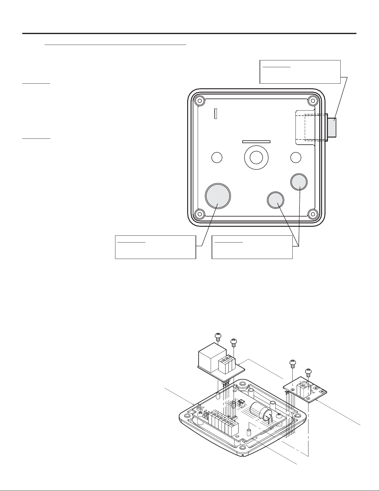
1.1Enclosure knock-out Instructions
Option A: Conduit Connection
1. Remove the red cap plug.
2. Install your pipe fitting (1/2 - 14 NPT male
end).
Page 2
Option A: 1 / 2-14 MPT
Red Cap Plug
(for pipe fitting)
Option B: Liquid-Tight Connections
Internal View
1. Remove knock-out(s) using a screwdriver.
2. Trim edge(s) with a knife and remove sharp
edges.
3. Install the provided liquid-tight connector(s).
Option B: 3/4 DIA.
Knock-out
(large liquid-tight connector)
Option B: 1/2 DIA.
Knock-out
(small liquid-tight connector)
Notes:
For the large liquid-tight connector (3/4” Knock-out), the acceptable cable diameter is between .200 - .394 in (5.1 -
10.0 mm).
For the small liquid-tight connector (½”Knock-out), the acceptable cable diameter is between .118 - .255 in (3.0 -
6.5 mm).
1.2Optional Circuit Board Installation
CAUTION: DISCONNECT POWER
SOURCE BEFORE SERVICING.
1. Carefully align optional board’s Pin
Header with the Pin Header socket
located on the main circuit board.
2. Press firmly into place.
3. Secure the board with the two screws
provided.
F-2000
Enclosure
Cover
(OPTIONAL BOARD)
N.C.
N.O.
C
F-2000-PC
F-2000-PB
(MAIN BOARD)
F-2000-RT
F-2000-AO
(OPTIONAL
BOARD)
Page 3
Page 3
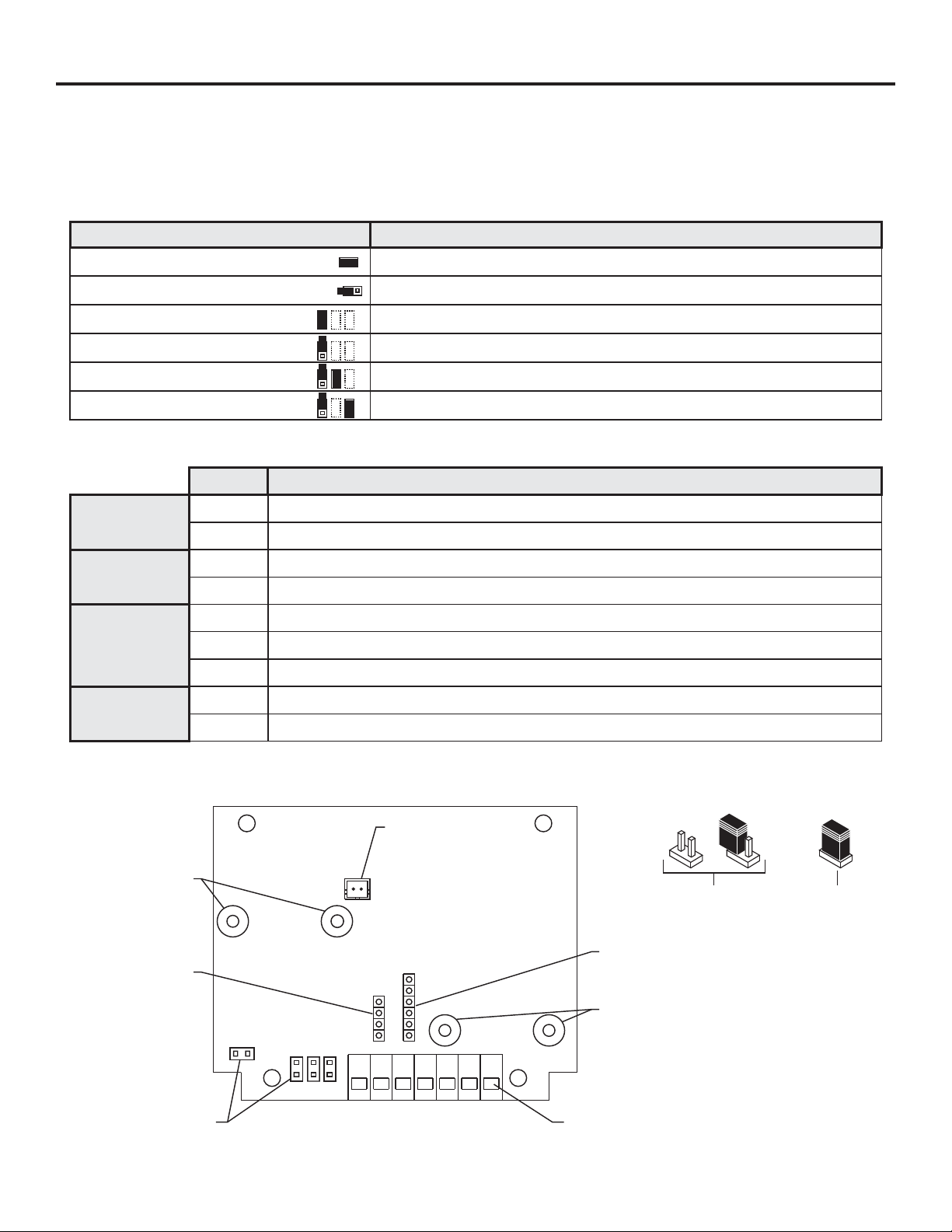
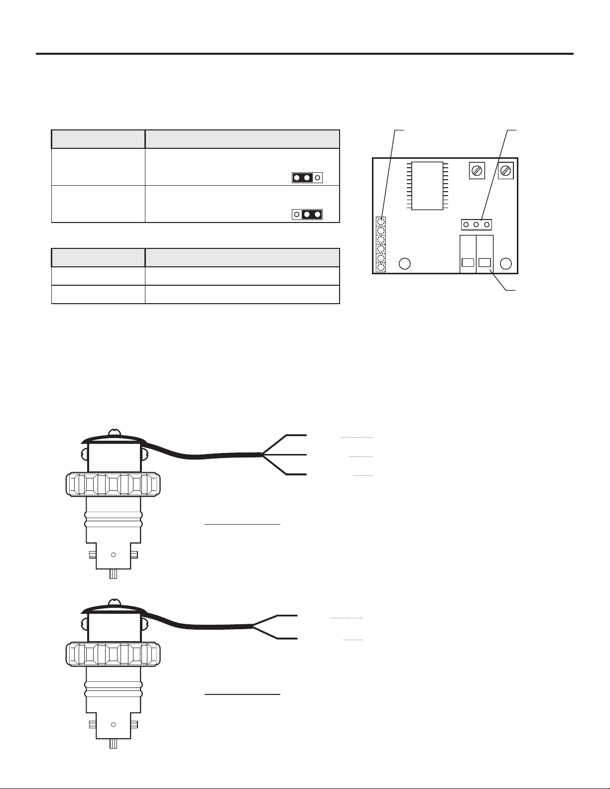
1.3Model RT Circuit Board Wiring
CAUTION: DISCONNECT POWER SOURCE BEFORE SERVICING.
Jumper Configuration
F-2000
Jumpers
J1 Installed
J1 Left Open
J2 Installed
J2 Left Open
J3 Installed and J4 Left Open
J3 Left Open and J4 Installed
Terminal Configuration
Terminal Function
Supply power
input
AC coil sensor
input
6
5
2
3
1
Hall Effect
sensor input
2
3
Open connector
pulse output
(from sensor)
7
4
Function
Battery Input (4 - 1.5 VDC, AA Cells)
Plug-In Transformer (115 VAC / 15 VDC, 220 VAC / 15 VDC, 230 VAC / 15 VDC)
Front Panel Programming is Disabled
Front Panel Programming is Enabled (factory default)
Hall Effect Sensor Input
AC Coil Sensor Input
Positive (+) power input (red wire from battery pack, or black with stripe wire from 15 VDC plug-in transformer)
Ground (-) power input (black wire from battery pack or 15 VDC plug-in transformer)
Ground (-) input (black wire from coil sensor body)
Pulse input (yellow or red wire from coil sensor body)
Positive (+) input (red wire from hall effect sensor)
Ground (-) input (black wire from hall effect sensor)
Pulse input (bare wire from hall effect sensor)
NPN positive (+) signal output
NPN negative (-) signal output
(Max voltage: 24VDC, Max load: 15mA, 2k ohm pull-up recommended.)
F-2000 RT Board
F-2000 PC Board
Mounting Screw
Bushings
SIP Socket for
F-2000 PC Board
Jumpers
BAT = ON
J1
J3
J2
PHM
Backup Battery
Connector
J4
7654321
SIP Socket for
F-2000 AO Board
F-2000 AO Board
Mounting Screw
Bushings
Terminal Blocks
Jumper Positions
Jumper Not
Installed (open)
Jumper
Installed
Page 4
F-2000
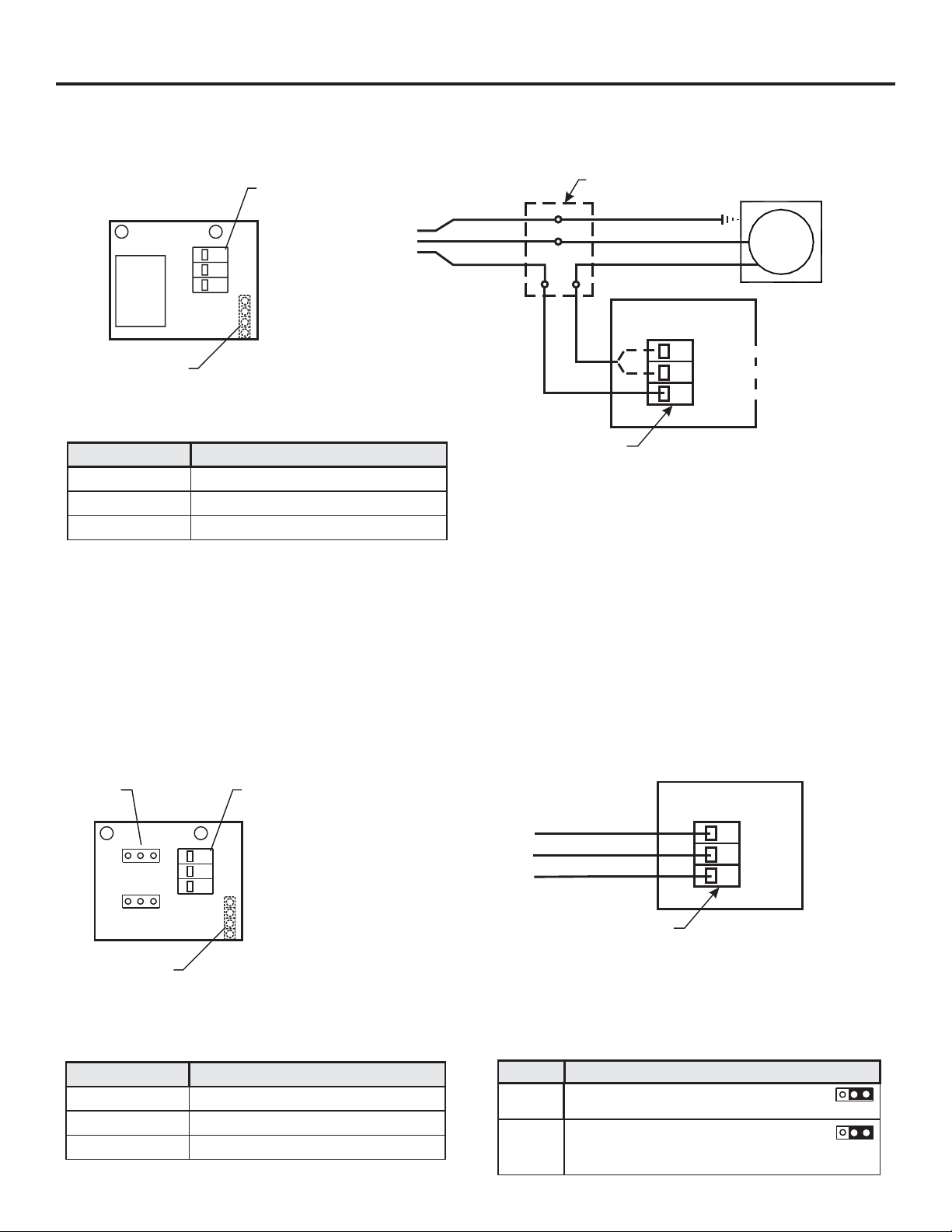
1.4Model PC Circuit Board Wiring
CAUTION: DISCONNECT POWER SOURCE BEFORE SERVICING.
Page 4
Terminal
Relay
Block
3
NC
2
NO
1
C
Earth Ground (green)
AC
Pin Header
(Other side)
Terminal Configuration
Terminal Terminal Block Connections
1
2
3
Output Type: Isolated relay SPDT (single poll double throw), NO / NC
Max. Load: 8 amps (AC) @ 115 VAC, 220 VAC, 230 VAC
Max. Voltage: 250 VAC, 125 VDC
Common
NO (Normally Open) contact
NC (Normally Closed) contact
7 amps (DC) @ 30 VDC (resistive load)
Common (-)
Hot (+)
Junction Box (not supplied)
Earth Ground (green)
Load Neutral (-)
Load Hot (+)
F-2000-PC Board
3-position
Terminal Block
External
Equipment
Load
(normally Closed Contact)
3
NC
(normally Open Contact)
NO
2
(common Contact)
1
C
1.5Model PB Circuit Board Wiring
CAUTION: DISCONNECT POWER SOURCE BEFORE SERVICING.
Jumpers
JP1
JP2
NC
IN
NO
EX
Pin Header
(Other side)
Terminal Configuration
Terminal Terminal Block Connections
1
2
3
Voltage input (+)
Switched output (NO/NC)
Ground (-)
3
2
1
Terminal
Block
G
OUT
V
Output Type: Non-Isolated contact closure switch, NO / NC
Max. Load: 100 milliamps (.10 amp)
Max. Voltage: 30 VDC if JP2 is set for external power.
15 VDC if JP2 is set for internal power and F-2000 is powered by plug-in transformer.
3 VDC if JP2 is set for internal power and F-2000 is powered by Batteries.
Max. Power: 3 Watts
Ground (-)
Switched Output (NO/NC)
Supply (+) (voltage input)
3-position
Terminal Block
Jumper Configuration
Jumper SettingsJumper
JP1
JP2
NC = Normally closed contacts
NO = Normally open contacts (default)
IN = Internal power
EX = External power (default)
Note: See above voltage limits
F-2000-PB Board
G
3
2
OUT
1
V
JP1
NC
NO
JP2
IN
EX
Page 5
Page 5
1.6Model AO Circuit Board Wiring
CAUTION: DISCONNECT POWER SOURCE BEFORE SERVICING.
Jumper Configuration
Output Jumper Settings
Connect P1 & P2 (leave P3 open) (factory
4-20 Milliamp
0-10 Volts DC
Terminal Configuration
Terminal Number Terminal Block Connections
default), Max Load = 250 Ohms
Connect P2 & P3 (leave P1 open), Max Load =
500 Ohms
P2
P3P1
P2
P3P1
Pin Header
(other side)
A
-
P2
21
F-2000
3 position
jumper Pin
P3P1
V
+
1
2
Output Type: Linear, Non-Isolated, powered loop.
Loop resistance: 250 ohm maximum for 4-20mA output
Positive (+) Analog Output Signal
Negative (-) Analog Output Signal
500 ohm maximum for 0-10 V DC
1.7Model FHXX and FCXX Sensor wiring
Model FHXX
Note: Output type - current sinking type hall effect sensor (13.5mA max).
Pull-up resistor is recommended. 5k ohm across red & bare wires.
RED
BARE
BLACK
Terminal
Block
Input Supply Voltage (+ 6 to 24 Vdc)
Signal Output (square wave)
Ground (-)
Model FCXX
RED
BLACK
Signal Output (Sine wave)
Ground (-)
Page 6

F-2000
2.0 HOW TO OPERATE THE MODEL PC and MODEL PB
2.1What Was The MODEL PC and PB Designed To Do?
In addition to the features of the MODEL RT, the model PC includes a single SPDT relay which can be used to
switch an external component such as a pump, valve, alarm buzzer, etc., on and off in order to assist in the
control of a process. The relay setpoints must be assigned to either the rate mode, the batch (total) mode, or
turned off. The MODEL PC cannot be battery operated.
The MODEL PB offers all of the features of the MODEL PC but includes a contact closure switch instead of a
relay and may be battery operated.
!
High level flow rate alarm.
!
Low level flow rate alarm.
!
High and low level flow “range” alarm.
!
Manual start or automatically timed start batch processing.
!
Proportional chemical feed injector pump control.
2.2What Features Are Available?
!
All controls are front panel programmable.
!
MODEL PC Max. switching load 8 Amp at - 115 VAC, 230 VAC, 220 VAC; 7 Amp at 30 VDC (resistive load).
!
MODEL PB Max. switching load 100 milliamp at 30 VDC.
!
NO / NC contact.
!
Rate alarms can be latched requiring a manual reset.
!
Programmable “alarm release value” provides hysteresis to prevent relay flickering (see page 28).
!
High and low range alarms can be independently programmed.
!
Alarm delay timer temporarily silences alarms for a programmed time from 0-999 seconds.
!
Independent display and resetting of batch count and batch amount.
!
Front panel clearing of batch counts and amounts can be disabled.
!
Turn on / off external devices, for a programmable time from 0-999 seconds per batch.
Page 6
2.3How Do I Program The MODEL PC & PB?
The Model PC & PB setpoints must be assigned to either the rate mode (option 1), the batch (total) mode
(option 2), or turned off (option 3).
Option 1 - Assign the setpoints to the RATE mode for applications involving the switching of external devices,
such as alarms or valves, when the rate of flow is greater than or less than the programmed flow
RATE value. The Model PC and PB is used to monitor flow RATE in this mode. Example: High or
low flow rate alarms.
Option 2 - Assign the setpoints to the BATCH mode for applications involving the switching of external devices
such as chemical metering pumps, centrifical pumps, solenoid valves, etc., when the amount of flow
is greater than or less than the programmed batch amount value. In this mode, the Model PC is used
to monitor flow total. Example: Manual batch processing or proportional feed rate control.
Option 3 - The OFF mode opens the relay contacts regardless of the flow conditions. The setpoints are not
assigned.
SETPOINT MODE SELECTION PROGRAMMING SCREEN OPTIONS
OPTION
Option - 1 (page 27)
Option - 2 (page 32)
Option - 3
SELECTION FUNCTION
Setpoint - RATE Relay Setpoints are assigned to flow RATE mode.
Setpoint - BATCH Relay Setpoints are assigned to BATCH (accumulative or “total”) mode.
Setpoint - OFF Relay Setpoints are not assigned. Relay is not energized.
Page 7

Page 7
F-2000
OPTION 1. RELAY SETPOINTS ARE ASSIGNED TO THE RATE MODE.
When the setpoint mode selection screen is assigned to RATE, the following program screens are available:
PROGRAMMING SCREEN PROGRAMMING SCREEN FUNCTION
Setpoint - RATE - 1 High alarm flow RATE trigger value. (Factory default value = 000001)
Setpoint - RATE - 2 High alarm flow RATE release value. (Factory default value = 000001)
Setpoint - RATE - 3 Low alarm flow RATE trigger value. (Factory default value = 000001)
Setpoint - RATE - 4 Low alarm flow RATE release value. (Factory default value = 000001)
Setpoint - RATE - 5 Alarm reset delay time from 000 - 999 seconds. (Factory default value = 000)
The relay setpoints may be assigned in one of three ways:
Choice 1. High Alarm Only
The High Alarm Trigger Setpoint energizes the relay at a high flow rate value (high flow alarm). A single
trigger value is assigned to a flow rate value greater than the normal flow rate. The relay will energize
when the flow rate increases to the programmed value. In this option, the low trigger and release values
are not used and should be programmed to a value of zero.
Choice 2. Low Alarm Only
The Low Alarm Trigger Setpoint energizes the relay at a low flow rate value (low flow alarm). A single
trigger value is assigned to a flow rate value less than the normal flow rate. The relay will energize when
the flow rate decreases to the programmed value. In this option, the high trigger and release values are
not used and should be programmed to a value of zero.
Choice 3. High and Low Range Alarm Setpoints
The Range Alarm Setpoints energize the relay at both the high and low flow rate values (out-of-range
alarm). Both the high and low trigger values must be assigned creating an acceptable range of flow. The
relay will energize when the flow rate increases or decreases out of the acceptable range.
The relay action may be programmed in three ways:
Choice 1. Manual Unlatching requires the user to press the clear setpoints button to unlatch the relay (turn off the
alarm). The relay is energized and latched when the trigger value is reached and remains energized and
latched until the clear setpoints button is pressed.
To enable the feature, program the trigger and release values to the same value.
Choice 2. Automatic Unlatching requires the programming of a separate release point. When the setpoint is
triggered, the relay will automatically unlatch when this release value is crossed.
To enable the feature, program a different trigger and release value. The high release value must be less
than the high trigger value. The low release value must be greater than the low trigger value.
Choice 3. The Relay is Deactivated
To deactivate the relay, program all trigger and release values to zero.
NOTE: When latched, regardless of how the relay action is programmed, the relay may be unlatched manually by
pressing the front panel “clear setpoints” button. However if there is still an alarm condition (high or low trigger
value is exceeded), the relay will immediately re-latch. An alarm reset delay time can be programmed which will
delay the re-latching of the relay even though the alarm condition still exists. If the relay is being used to switch an
audible alarm, this feature allows for temporarily silencing the alarm, allowing time to affect repairs, without
actually disabling the alarm feature. The programmable time range is from 0-999 seconds.
Page 8

F-2000
FLOW RANGE ALARM EXAMPLE
Page 8
High Alarm
High setpoint trigger value 250.0 GPM
Hysteresis
High setpoint release value 240.0 GPM
Flow
Low setpoint release value 160.0 GPM
Hysteresis
Low setpoint trigger Value 150.0 GPM
Low Alarm
Note: If the relay flickers on and off due to unstable flow, readjust
the release value to increase the amount of hysteresis.
2.4Programming the MODEL PC & PB when the setpoints are assigned to rate.
Caution: An emergency shut off switch for externally controlled electrical equipment is recommended.
Note: The F-2000 must be powered by the AC Adapter.
Nominal
Range
Note: While in the programming mode, if no buttons are pressed within twenty seconds, the programming mode
is automatically exited without saving the input of the last screen.
Step 1 Enter the programming mode and assign the setpoints to the RATE mode.
!
Press for at least 1.25 seconds.
!
Press to by-pass the first six program screens until you reach the Rate Setpoint Screen (seventh screen).
!
Press to select Rate Setpoint On.
!
Press .
ENTER
ENTER
CLEAR
TOTAL
ENTER
Step 2 Enter the High Alarm Trigger Value or 0.
!
Press to select the digit or decimal point to be modified. The selected digit will blink.
!
Press to change the selected digit. Note: Setting the value to zero disables the High Alarm.
!
Press when you have entered your desired High Alarm Trigger Value.
CLEAR
SETPOINT
CLEAR
TOTAL
ENTER
RATE SETPOINT
00000
RATE SETPOINT
O
Page 9

Page 9
Step 3 Enter the High Alarm Release Value or 0.
!
Press to select the digit or decimal point to be changed. The selected digit will blink.
!
Press to change the selected digit. Note: This value must not be greater than the High Alarm Trigger Value.
CLEAR
SETPOINT
CLEAR
TOTAL
F-2000
000002
RATE SETPOINT
!
Press when you have entered your desired High Alarm Release Value.
ENTER
Step 4 Enter the Low Alarm Trigger Value or 0.
!
Press to select the digit or decimal point to be changed. The selected digit will blink.
!
Press to change the selected digit. Note: Setting the value to zero disables the Low Alarm.
!
Press when you have entered your desired Low Alarm Trigger Value.
CLEAR
SETPOINT
CLEAR
TOTAL
ENTER
Step 5 Enter the Low Alarm Release Value or 0.
!
Press to select the digit or decimal point to be changed. The selected digit will blink.
!
Press to change the selected digit. Note: This value must not be less than the Low Alarm Trigger Value.
!
Press when you have entered your desired Low Alarm Release Value.
CLEAR
SETPOINT
CLEAR
TOTAL
ENTER
000003
RATE SETPOINT
000004
RATE SETPOINT
Step 6 Enter the Alarm Reset Delay Timer in seconds or press
ENTER
to bypass this screen.
The alarm will be silenced (relay de-energized) for the programmed amount of time when is pressed.
After the delay time, if the alarm condition still exists, the relay will re-energize. This feature allows the user to
temporarily silence the alarm without disabling the alarm feature. The programmed time range is from 0 to 999
seconds.
!
Press to select the digit to be changed.
!
Press to change the selected digit. Note: Setting the value to zero disables the Alarm Reset Delay Timer.
!
Press to save your Alarm Reset Delay Time.
Step 7 Press and hold down for at least 1.25 seconds to exit.
CLEAR
SETPOINT
CLEAR
TOTAL
ENTER
ENTER
RATE SETPOINT
CLEAR
SETPOINT
0005
Page 10

F-2000
2.5Examples of Setpoint Assigned to Rate.
Example 1: An audible alarm must sound when the flow rate goes out of the range of 25 to 35 gallons
per minute.
Alarm
Page 10
Trigger
Trigger
35.0 GPM
25.0 GPM
Release 34.0 GPM
Flow
Release
Alarm
Step 1 Set the SETPOINT MODE SELECTION screen to SETPOINT - RATE.
Step 2 Set SETPOINT - RATE - 1, screen for a high range trigger value of 35.0.
Step 3 Set SETPOINT - RATE - 2, screen for a high range release value of less than 35 and greater than 25.
(If latching alarm is required, set the release value to 35).
Step 4 Set SETPOINT - RATE - 3, screen for a low range trigger value.
Step 5 Set SETPOINT - RATE - 4, screen for a low range release value of greater than 25 and less than 35.
(If latching alarm is required, set the release value to 25).
Step 6 Set SETPOINT - RATE - 5, to the desired alarm silencing delay time of 0 - 999 seconds(optional).
Step 7 Wire the alarm to the normally open terminals of the relay terminal block. See page 16.
Example 2: An audible alarm must sound if the flow rate goes below 82.5 cubic meters per hour.
26.0 GPM
Flow
Trigger 82.5 MH
3
Alarm
Release 84.0 MH
Step 1 Set the SETPOINT MODE SELECTION SCREEN to SETPOINT - RATE.
Step 2 Set SETPOINT - RATE - 1, screen for a high trigger value of 0. (High alarm not used, bypass).
Step 3 Set SETPOINT - RATE - 2, screen for a high release value of 0. (High alarm not used, bypass).
Step 4 Set SETPOINT - RATE - 3, screen for a low trigger value of 82.5.
Step 5 Set SETPOINT - RATE - 4, screen for a low release value of greater than 82.5 (example: 84.0).
Step 6 Set SETPOINT - RATE - 5, to the desired alarm silencing delay time of 0 - 999 seconds (optional).
Step 7 Wire the alarm to the normally open terminals block. See page 16.
3
Page 11

Page 11
Example 3: A solenoid valve must open if the flow rate goes above 225 gallons per minute.
F-2000
Open Valve
Trigger
225 GPM
Release 220 GPM
Flow
Step 1 Set the SETPOINT MODE SELECTION SCREEN] to SETPOINT - RATE.
Step 2 Set SETPOINT - RATE - 1, screen for a high trigger value of 225.
Step 3 Set SETPOINT - RATE - 2, screen for a high release value of less than 225. Example: 220
Step 4 Set SETPOINT - RATE - 3, screen for a low trigger value of 0. (Low alarm not used).
Step 5 Set SETPOINT - RATE - 4, screen for a low release value of 0. (Low alarm not used).
Step 6 Set SETPOINT - RATE - 5, to the desired alarm delay silencer time from 0 - 999 seconds (optional).
Step 7 Wire the value to the normally open terminals of the relay terminal block. See page 16.
Page 12

F-2000
Page 12
OPTION 2. RELAY SETPOINTS ARE ASSIGNED TO THE BATCH MODE.
BATCH AMOUNT - Two types of batch applications are available, manually started batches and automatically started
batches. Both types require the programming of a batch amount value.
In a manually started batch, the relay is energized manually by the user when the front panel clear setpoint
button is pressed and de-energized when the batch amount is reached. In this mode, the relay is switching a
valve or other device that is controlling the flow being measured.
In an automatically started batch, the relay is energized and the external equipment timer is started when the
batch amount is reached. The relay is de-energized at the end of the timer cycle.
AUTO RESET ON/OFF - The auto reset must be turned off for manual start batches and turned on for auto start batches.
EXTERNAL EQUIPMENT TIMER - The external equipment timer is only used with auto start batches.
When the setpoint mode selection screen is assigned to BATCH, the following program screens are available:
PROGRAMMING SCREEN PROGRAMMING SCREEN FUNCTION
Setpoint - BATCH - 1 Batch amount value.
Setpoint - BATCH - 2
Setpoint - BATCH - 3 External equipment timer amount in seconds (0 - 999).
Auto reset on or off (on for auto timed batches and proportional feed control, off for manually reset batches)
MANUAL BATCH START APPLICATION
Manual batch start requires pressing the clear setpoints button to energize the relay. The relay de-energizes when
the Batch Amount is reached. The clear setpoints button must be pressed again to begin the next batch.
CAUTION: A SEPARATE EMERGENCY SHUT-OFF SWITCH FOR EXTERNAL EQUIPMENT IS RECOMMENDED.
Application 1. Manual Batch Operation
In this operation, the relay is used to switch a device such as a valve or pump, that is controlling the flow being
measured.
Example: a pump is turned on and off to fill containers to a preset amount of fluid. The fluid being pumped is also
the fluid being measured by the F-2000.
1. The pump is wired to the normally open relay contacts of the F-2000.
2. Manually pressing the front panel “clear setpoints” button starts the batch by energizing the relay, which
switches on power to the pump. The SETPOINT display icon illuminates.
3. The displayed Batch Number increments by one.
4. The displayed Batch Amount increases based on the pump flow rate.
5. When the programmed Batch Amount is reached, the relay de-energizes, turning off the pump. The SETPOINT
display icon disappears.
6. The batch is complete.
Note: The batch may be interrupted and re-started by pressing the “clear setpoints” button. The SETPOINT
display icon flashes.
AUTOMATIC BATCH START APPLICATION
Automatic Batch Start requires programming the EXTERNAL EQUIPMENT TIMER to a specific time from 000 999 seconds. When the batch amount is reached, the relay energizes and the timer starts. The relay de-energizes
when the number of seconds programmed is reached.
Page 13

Page 13
Application 2. Proportional Chemical Feed Operation
In this operation, the relay is used to switch a device such as a valve or pump, that is being controlled by the flow
being measured.
Example: A chemical injection pump is turned on for a preset amount of time when the Programmed Batch
Amount is reached, thus injecting an amount of chemical per an amount of measured flow.
1. The chemical injection pump is wired to the normally open relay contacts.
2. The flow measurement begins.
3. The displayed Batch amount increases based on the flow rate being measured.
4. When the programmed Batch Amount is reached, the following occurs:
a. The external equipment timer begins.
b. The relay energizes turning on the chemical injection pump.
c. The Batch Amount Resets to zero.
d. The next batch flow rate measurement begins and the displayed Batch Amount increases.
e. When the External Equipment Timer cycle ends, the relay de-energizes turning off the chemical injection
pump.
5. The displayed Batch Number increments by one.
6. The batch is complete.
F-2000
Note: The chemical pump may be stopped and re-started by pressing the clear setpoints button.
Application 3. Automatically Timed Batching Operation
In this operation, the relay is used to switch a device, such as a valve or pump, that is controlling the flow being
measured.
Example: A solenoid valve is wired to the normally closed contact of the F-2000 relay. In the de-energized relay
state, the valve is energized and open, which permits the flow being measured to flow. When the programmed
batch amount is reached, the relay is energized, opening the relay circuit which closes the valve, and a time delay
cycle begins. After the time delay cycle, the relay de-energizes which opens the solenoid valve and the next batch
begins.
CAUTION: WHEN WIRED TO THE NORMALLY CLOSED CONTACTS OF THE RELAY, EXTERNAL EQUIPMENT
WILL BE ENERGIZED IF THE CLEAR SETPOINTS BUTTON IS PRESSED. A SEPARATE
EMERGENCY SHUT-OFF SWITCH FOR EXTERNAL EQUIPMENT IS RECOMMENDED.
1. The solenoid valve is wired to the normally closed contacts.
2. The flow measurement begins.
3. The displayed Batch Amount increases based on the flow rate being measured.
4. When the programmed Batch Amount is reached, the following occurs:
a. The time delay cycle (External Equipment Timer) begins.
b. The relay energizes closing the valve which stops the flow.
c. The batch amount resets to zero.
5. When the External Equipment Timer cycle ends, the relay de-energizes, opening the solenoid valve.
6. The displayed Batch Number increments by one.
7. The batch is complete.
Page 14

F-2000
Page 14
2.6Programming The MODEL PC & PB When Setpoints Are Assigned To Batch
Note: The F-2000 must be powered by the AC adapter.
CAUTION: A SEPARATE EMERGENCY SHUT-OFF SWITCH FOR EXTERNAL EQUIPMENT IS RECOMMENDED.
Step 1 Enter the programming mode and assign the setpoint to the BATCH mode.
!
Press for at least 1.25 seconds.
ENTER
BATCH SETPOINT
O
!
Press to by-pass the first six program screens until you reach the Batch Setpoint Screen (seventh screen).
!
Press to select Batch Setpoint ON.
!
Press .
Step 2 The Setpoint Batch-1 screen, Batch Amount Value is selected.
This screen is used to enter the batch amount value. The relay will energize when the
accumulated total flow equals the programmed value.
!
Press to select the digit or the decimal to be modified. The selected digit will blink.
!
Press to change the selected digit.
!
Press when you have finished.
Step 3 The Setpoint Batch-2 screen, Auto Batch Start On or Off is enabled.
This screen is used to toggle the auto Batch Start function On and Off.
Note: Select On for auto-Start Batches and Off for manual Start Batches.
ENTER
CLEAR
TOTAL
ENTER
CLEAR
SETPOINT
CLEAR
TOTAL
ENTER
00000
BATCH SETPOINT
2
BATCH SETPOINT
O
!
Press to select On or Off.
!
Press when you have finished.
Step 4 The Setpoint Batch-3 screen, external equipment Timer amount
This screen is used to enter the number of seconds per batch that the relay will be energized.
Note: Set to zero for manual Start Batch operations.
!
Press to select the digit to be modified.
!
Press to change the selected digit.
!
Press when you’ve finished.
CLEAR
TOTAL
ENTER
(in seconds) is displayed.
CLEAR
SETPOINT
CLEAR
TOTAL
ENTER
3
BATCH SETPOINT
000
Page 15

Page 15
2.7Examples of Setpoint Assigned To Batch
Example 1: Proportional feed application. A chemical feed pump must run for 3 seconds for every 12.57
liters of flow measured.
Step 1 Set the SETPOINT MODE SELECTION screen to SETPOINT - BATCH.
Step 2 Set SETPOINT - BATCH - 1 screen for a batch amount value of 000012.57
Step 3 Set SETPOINT - BATCH - 2 screen for automatic batch start.
Step 4 Set SETPOINT - BATCH - 3 screen for external equipment timer on-time of 003 seconds.
Step 5 Wire the pump to the normally open terminals of the relay terminal block.
Step 6 The pump will start automatically when the batch amount is reached.
F-2000
Example 2: Manual batch application. In a truck depot, an attendant must open a solenoid valve
allowing 2,000 gallons of water to flow into each truck.
Step 1 Set the SETPOINT MODE SELECTION screens to SETPOINT - BATCH
Step 2 Set SETPOINT - BATCH - 1 screen for a batch amount value of 00002000
Step 3 Set SETPOINT - BATCH - 2 screen for automatic BATCH START OFF.
Step 4 Set SETPOINT - BATCH - 3 screen for external equipment timer on-time of 000 seconds.
Step 5 Wire the solenoid valve to the normally open terminals of the relay terminal block.
Step 6 Press to begin the first batch.
CLEAR
SETPOINT
Page 16

F-2000
3.0 HOW TO OPERATE THE MODEL AO
3.1What Was The MODEL AO Designed To Do?
!
Output a 4-20mA or 0-10VDC signal which is proportional to the flow.
3.2What Features Are Available?
!
Front panel programmable zero and span.
!
20-4mA and 10-0VDC inverted logic capabilities.
!
Front programming can be disabled for security.
!
4-20mA or 10VDC output signal (factory default) selected via jumper pin located on the circuit board.
3.3How Do I Program The MODEL AO?
Note: The F-2000 must be powered by AC Adapter
Note: The output signal can be inverted. Either the low or the high output signal may be assigned to the lower or
Programming Screen Programming Screen Function
Page 16
MA 1
MA 2
Input the desired flow rate which corresponds to an output signal of 4mA or 0VDC. This
value may be either the high or the low point in the range.
Input the desired flow rate which corresponds to an output signal of 20mA or 10VDC. This
is the opposite range point from the MA 1 setting (above).
Step 1 MA 1, Flow Rate at Low Output Signal (4mA or 0VDC).
!
Press for at least 1.25 seconds to activate programming mode.
!
Press to toggle through the different display screens until you reach the MA screen.
!
Press to select the digit to be changed. Note: The selected digit will blink.
!
Press to change the selected digit.
!
Press .
ENTER
ENTER
CLEAR
SETPOINT
CLEAR
TOTAL
ENTER
Step 2 MA 2, Flow Rate at High output Signal (20mA or 10VDC).
!
Press to select the digit to be changed.
CLEAR
SETPOINT
MA
00000
00000
2
MA
!
Press to change the selected digit.
!
Press .
CLEAR
TOTAL
ENTER
Page 17

Page 17
4.0 Programming Menu Flow Chart
F-2000
ENTER
ENTER
ENTER
ENTER
ENTER
ENTER
ENTER
SCREEN
000000
RATE
00000
2
RATE
3
RATE
O00000
TOTAL
00000
2
TOTAL
3
TOTAL
MODEL PC UNITS ONLY
CLEAR
TOTAL
RATE sETPOINT
OFF
OFF
OFF
sETPOINT
DESCRIPTION
MODIFYING
RATE 1 - Rate Scale Factor
RATE 2 - Rate Decimal Factor
RATE 3 - Battery Save Mode On / Off
TOTAL 1 - Total Scale Factor
TOTAL 2 - Total Decimal Factor
TOTAL 3 - Clear Total Enable On / Off
SETPOINT MODE ASSIGN - on rate / on batch / off
Setpoint ON - Assigned to RATE
CLEAR
SETPOINT
CLEAR
TOTAL
CLEAR
TOTAL
CLEAR
SETPOINT
CLEAR
TOTAL
CLEAR
TOTAL
Or
Or
CLEAR
TOTAL
CLEAR
TOTAL
ENTER
ENTER
ENTER
ENTER
ENTER
CLEAR
TOTAL
BATCH SETPOINT
ENTER
ENTER
ENTER
MODEL AO UNITS ONLY
00000
RATE SETPOINT
00000
2
3
4
5
BATCH SETPOINT
2 OFF
BATCH SETPOINT
3
BATCH SETPOINT
RATE SETPOINT
00000
RATE SETPOINT
00000
RATE SETPOINT
000
RATE SETPOINT
00000
00000
Setpoint Rate 1 - High Alarm Trigger
Setpoint Rate 2 - High Alarm Release
Setpoint Rate 3 - Low Alarm Trigger
Setpoint Rate 4 - Low Alarm Release
Setpoint Rate 5 - Alarm Delay Timer
Setpoint ON - Assigned to BATCH
Setpoint Batch 1 - Batch Amount
Setpoint Batch 2 - Auto Reset On / Off
Setpoint Batch 3 - External Equip. Timer
CLEAR
SETPOINT
CLEAR
SETPOINT
CLEAR
SETPOINT
CLEAR
SETPOINT
CLEAR
SETPOINT
CLEAR
SETPOINT
CLEAR
SETPOINT
CLEAR
SETPOINT
Or
Or
Or
Or
Or
Or
Or
Or
CLEAR
TOTAL
CLEAR
TOTAL
CLEAR
TOTAL
CLEAR
TOTAL
CLEAR
TOTAL
CLEAR
TOTAL
CLEAR
TOTAL
CLEAR
TOTAL
ENTER
ENTER
00000
MA
00000
2
MA
MA-1 - Low Analog Out Value
MA-2 - High Analog Out Value
CLEAR
SETPOINT
CLEAR
SETPOINT
Or
Or
CLEAR
TOTAL
CLEAR
TOTAL
Page 18

Warranty
!
Blue-White flowmeters are warranted to be free from defects in material and workmanship for 12 months from date of
factory shipment. Warranty coverage is limited to repair or replacement of the defective flowmeter only.
!
This warranty does not cover damage to the flowmeter that results from misuse or alterations, nor damage that occurs
as a result of: meter misalignment, improper installation, over tightening, use of non-recommended chemicals, use of
non-recommended pipe dopes or adhesives, excessive heat or pressure or allowing the meter to support the weight of
related piping.
!
Flowmeters are repaired at the factory only. Call or write the factory to receive a RA (return authorization) number.
Carefully pack the flowmeter to be returned, including a brief description of the problem, chemical used, and a description of the application. Note: Write the RA number on the outside of the shipping carton.
!
Prepay all shipping costs. The factory does not accept C.O.D. Shipments. Damage that occurs during shipping is the
responsibility of the sender.
Users of electrical and electronic equipment (EEE) with the WEEE marking per Annex IV of
the WEEE Directive must not dispose of end of life EEE as unsorted municipal waste, but
use the collection framework available to them for the return, recycle, recovery of WEEE
and minimize any potential effects of EEE on the environment and human health due to the
presence of hazardous substances. The WEEE marking applies only to countries within the
European Union (EU) and Norway. Appliances are labeled in accordance with European
Directive 2002/96/EC.
P.N. 80000-390 Rev 4/09/2009
Contact your local waste recovery agency for a Designated Collection Facility in your area.
 Loading...