

Page 1
Blue-White
Industries, Ltd.
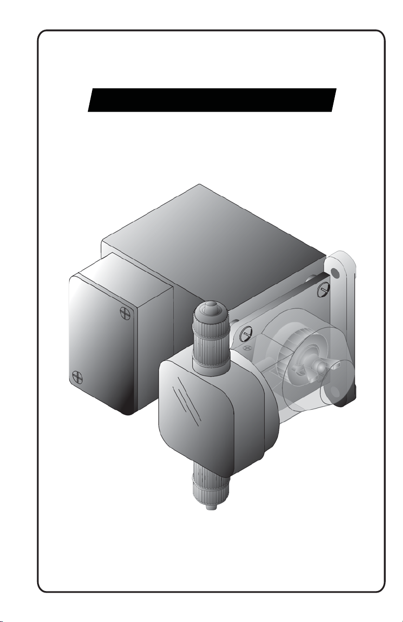
DIAPHRAGM INJECTOR
MODEL C-600P & C-600HV
®
5300 Business Drive
Huntington Beach, CA 92649
USA
Phone: 714-893-8529 FAX: 714-894-9492
E-mails: sales@blue-white.com or techsupport@blue-white.com
www.blue-white.com
Page 2

TABLE OF CONTENTS
SECTION HEADING PAGE
1 Introduction 2
2 Specifications 2
3 Features 3
4 How to install the metering pump 3
4.1 Mount Location 4
Installation 5
4.2 Electrical connections 6
4.3 How to install the tubing and fittings 7
5 How to operate the metering pump 9
5.1 Adjusting the Pump Output - Standard Models 9
5.2 Adjusting the Pump Output - Fixed cycle timer Models 9
5.3 Measuring the pump’s output - volumetric test 10
6 How to maintain the metering pump 10
6.1 Routine inspection and cleaning 10
6.2 How to clean the metering pump 10
Exploded View (C-600HV) 11
Exploded View (C-600P) 13
1.0 Introduction
Thank you for purchasing the positive displacement metering pump.
The pump is designed to inject chemicals into piping systems.
All models are equipped with a top mounted mechanical flow rate
adjustment knob. Optional on/off cycling timers are available.
2.0 Specifications
Maximum Working Pressure 125 psig / 8.6 bar* (C-600P)
20 psig 1. 37 bar* (C-600HV)
o o
Maximum Fluid Temperature 130 F / 54 C
Output Accuracy +/- 10% of maximum
o
(water @ 70 F, 0 psig, and 5’ suction lift)
o o
Ambient Temperature Range 14 to 110 F / -10 to 43 C
Enclosure Zinc - Metal
Duty Cycle Continuous
Maximum Viscosity 1,000 Centipoise
Maximum Suction Lift up to 10 ft. water
Power Requirements 115V60Hz 45 Watts
220V50Hz 45 Watts
230V60Hz 45 Watts
24V60Hz 45 Watts
Dimensions 6-1/2” H x 6-1/2” W x 5-3/4” D (C-600P)
7”H x 6-3/4” W x 6-1/8” D (C-600HV)
Weight 8 lb.
**Depending on Model number
Page 2
C-600
Page 3

* Most C-600P Models. C-600HV has max pressure rating of 20 PSIG
4.0 How To Install the Metering Pump
Note: All diagrams are strictly for guideline purposes only. Always
consult an expert before installing the metering pump into specialized
systems.
The metering pump should be serviced by qualified persons only.
4.1 Mounting Location
Choose an area located near the chemical supply tank, chemical
injection point and electrical supply. Install the pump where it can be
easily serviced.
!
Mount the pump to a secure surface or wall using the enclosed
hardware. Wall mount to a solid surface only. Mounting to drywall with
anchors is not recommended.
!
Keep the outlet (discharge) tubing as short as possible. Longer tubing
increases the back pressure at the pump head.
!
Do not mount the pump directly over your chemical container.
Chemical fumes may damage the unit. Mount the pump off to the side
or at a lower level than the chemical container.
!
Mounting the pump lower than the chemical container will gravity feed
the chemical into the pump. This “flooded suction” installation can
reduce the time required to prime the pump. Install a shut-off valve,
pinch clamp or other means to halt the gravity feed to the pump during
servicing.
!
Your solution tank should be sturdy. Keep the tank covered to reduce
fumes.
!
Be sure your installation does not constitute a cross connection with the
drinking water supply. Check your local plumbing codes.
CAUTION: PROPER EYE AND SKIN PROTECTION MUST BE WORN
WHEN INSTALLING AND SERVICING THE PUMP
3.0 Features
!
Double-ball ceramic check valves.
!
PVDF (Kynar) valve assemblies.
!
Viton o-rings.
!
High outlet pressure capability of 125 PSIG.*
!
Easy access, side mounted mechanical feed rate adjustment.
!
Ball bearing supported motor drive shaft.
!
Permanently lubricated ball bearing motor.
!
27:1 adjustment turn down ratio.
!
Easy servicing.
!
Includes suction tube foot valve & strainer, suction tube weight, suction
tubing, discharge tubing and injection fitting with internal back-flow
check valve and mounting hardware.
CAUTION - This pump has been evaluated for use with water only.
Page 3
C-600
Page 4
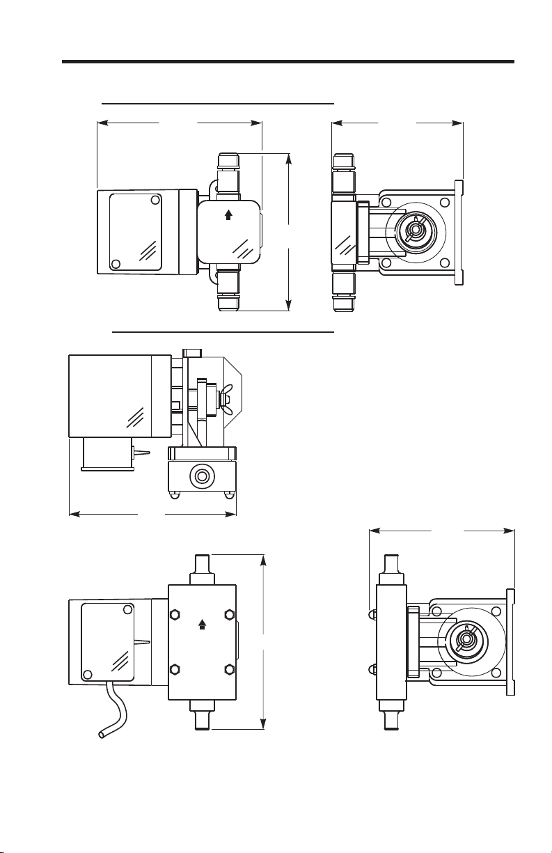
5-5/16”
134.9mm
0
1
2
3
4
5
6-3/4”
171.5mm
6-1/4”
158.8mm
C-600P
C-600HV
FIG. 4.1 DIMENSIONAL DRAWING
C-600
Page 4
0
1
2
3
4
5
6.75”
6.125”
7”
Page 5
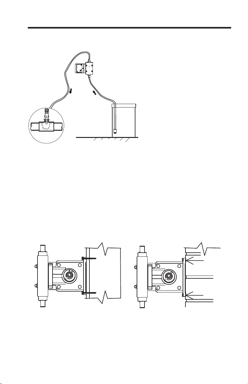
Stud
¼" & ½" NPT Injector
Suction Tube
(vertical)
Chemical
Container
Pumping unit
Discharge Tube
TYPICAL INSTALLATION
C-600
Page 5
0
0
1
1
2
2
3
3
4
4
5
5
WEATHER
RESISTANT
Masonry
Stud Mount
WALL MOUNTING
Page 6

4.2 Electrical Connections
Be certain to connect the pump to the proper supply voltage.
Using the incorrect voltage will damage the pump and may result in
injury. The voltage requirement is printed on the pump serial label.
Note: When in doubt regarding your electrical installation,
contact a licensed electrician.
The metering pump is supplied with a junction box for field wiring.
JUNCTION BOX MODELS -To reduce the risk of electric shock,
be certain that a grounding conductor is connected to the green
grounding screw located in the junction box.
FIG. 4.5 WIRING DIAGRAM - STANDARD MODELS
AC
MOTOR
INPUT
VOLTAGE
115V 60Hz
HOT
LEADWIRE
NEUTRAL
LEADWIRE
GROUND
LEADWIRE
230V 60Hz
BLUE or YELLOW*
BLUE
BROWN
RED
GREEN
GREEN
GREEN
MOTOR LEADWIRES
Neutral
Hot
Ground (green)
Earth Ground (green)
Common
Hot
AC
Input
Power
220V 50Hz
BLACK or YELLOW*
BLACK or YELLOW*
* Yellow leadwire : thermally protected motor
Black or Blue leadwire: standard impedance protected motor
24V 60Hz
WHITE
GREEN
BLUE*
C-600
Page 6
Page 7
4.3 How To Install the Tubing and Fittings
Inlet Tubing - Locate the inlet fitting of the pump head. Remove the
tube nut. Push the clear PVC suction tubing onto the compression barb
of the fitting. Use the tube nut to secure the tube. Hand tighten only.
Footvalve/Strainer -Trim the inlet end of the suction tubing so that the
strainer will rest in a vertical position, approximately one inch from the
bottom of the solution tank. This will prevent sediment from clogging the
strainer. Loss of prime may occur if the footvalve is permitted to lay on
the bottom of the solution tank in a horizontal position. Slip the ceramic
weight over the end of the suction tube. Press the footvalve/strainer into
the end of the tube. Secure the ceramic weight to the strainer. Drop the
strainer into the solution tank.
Outlet Tubing - Locate the outlet fitting of the pump head, Remove the
tube nut. Push the rigid outlet (discharge) tubing onto the compression
barb of the fitting. Use the tube nut to secure the tube. Hand tighten
only.
Trim the other end of the outlet tube leaving only enough slack to
connect it to the Injection/Check valve Fitting . Increasing the length of
the outlet tube increases the back pressure at the pump head, particularly when pumping viscous fluids.
Keep the inlet and outlet tubes as short as possible.
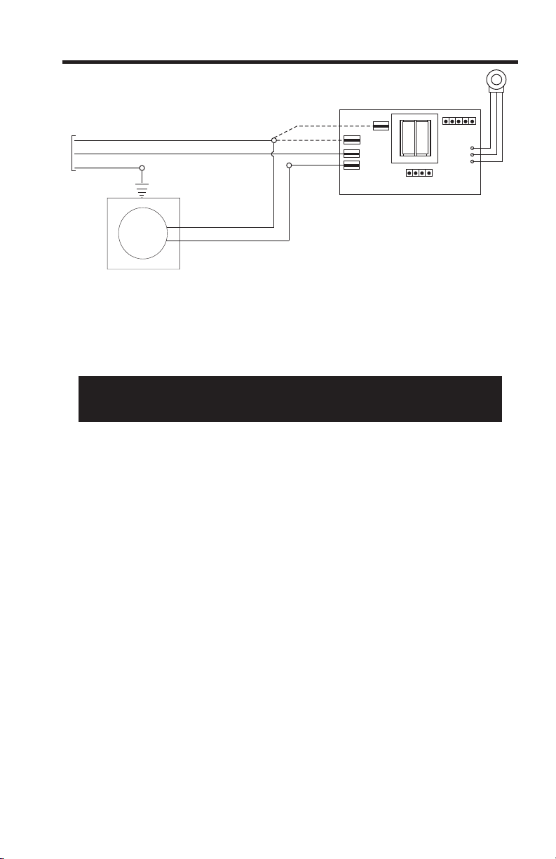
FIG. 4.6 WIRING DIAGRAM - FIXED TIMERS
CAUTION: PROPER EYE AND SKIN PROTECTION MUST BE WORN
WHEN INSTALLING AND SERVICING THE PUMP
Earth Ground (green)
120VAC
HOT
LOAD
220/230 VAC
Hot
Power
Cord
AC
MOTOR
Timer
Board
Neutral
Hot
Cycle Adjustment
Potentiometer
Common
C-600
Page 7
Page 8

C-600
Page 8
Discharge Tube
(Opaque P.E.)
Outlet Adapter
Tube Nut
Inlet Adapter
Tube Nut
Suction Tubing
(clear PVC)
Pump Head
FootValve
FootValve Assembly
Must be installed in
a vertical position.
FootValve Assemble
Ceramic
Weight
Suction Tubing
Suction Tubing
Clamp
Lock Nut
Footvalve Adapter
O-Ring
Ceramic Ball
O-Ring
O-Ring
Footvalve Body
Footvalve Strainer
FIG. 4.8 C-600P
FootValve Assy.
C-600P
PumpHead
C-600HV
PumpHead
C-600HV
FootValve Assy.
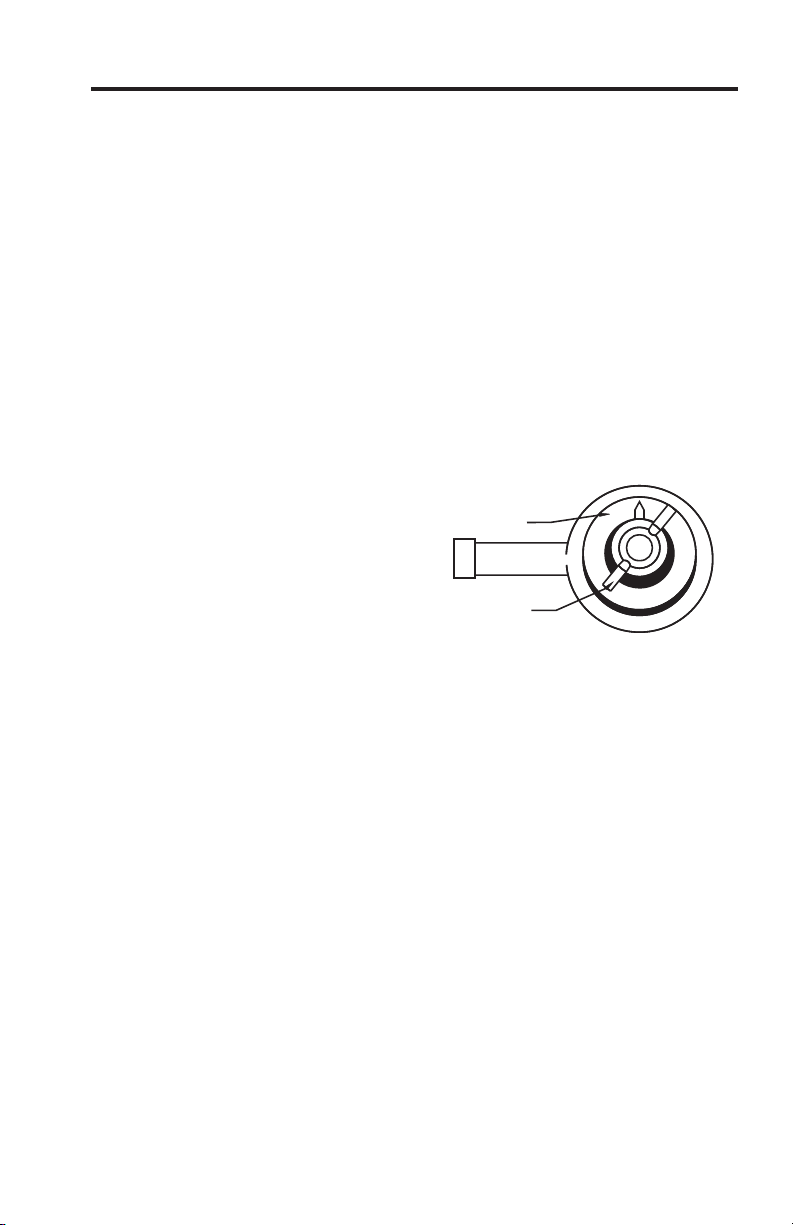
4.3.4 Injection/Check Valve Fitting Installation -
The Injection/Check valve fitting is designed
to install directly into either 1/4” or ½” female
pipe threads. This fitting will require periodic
cleaning, especially when injecting fluids that
calcify such as sodium hypochlorite. These
lime deposits and other build ups can clog the
fitting increasing the back pressure and
interfering with the check valve operation.
Install the Injection/Check valve directly into
the tee fitting. Do not install the fitting into a
pipe stud and then into the tee. The solution
must inject directly into the flow stream.
Use PTFE thread sealing tape on the pipe
threads. Push the opaque outlet (discharge)
tubing onto the compression barb of the
Injection/Check valve fitting. Use the tube nut
to secure the tube. Hand tighten only.
FIG. 4.9 C-600P
INJECTION/CHECK VALVE
TEE INSTALLATION AND EXPLODED VIEW
Page 9
5.0 How To Operate The Pump
5.1 Adjusting the Pump Output- The flow rate can be adjusted within a range
of approximately 10%-100% of maximum output (27:1 turndown ratio) by means
of a mechanical, cam type mechanism. The mechanism adjusts the pump’s
stroke length to 1 of 27 settings within the flow range. The pump’s output is
affected by the pressure of the system , the amount of suction lift, and the
viscosity of the fluid being injected into the pump must be over-sized to allow for
these factors. Sizing the pump to allow adjustment within the midrange is
preferred to maintain accuracy. Consult the factory for individual pump model
output curve data.
To adjust the pump output:
1. Make sure the pump is off before adjusting.
2. Loosen the wing nut.
3. Turn adjusting knob so the pointer is on the desired setting. Note: pump less
chemical at first, then re-adjust.
4. While holding the knob, tighten the wing nut to keep the knob at the desired
setting. Note: wing nut must be tight.
Priming The Pump
Each pump is factory tested with water. The test water is sealed in the pump
head keeping the valves dry to aid in priming. If the valves have dried or priming
is difficult due to back pressure, do the following:
1. Remove the opaque discharge tubing from the top valve fitting in the
pumphead.
2. Remove the top and bottom valve fittings and immerse in water to wet the
valves. Reinstall the fittings.
3. With the discharge tubing removed, start the pump. Stop the pump when the
fluid enters the pumphead.
4. Attach the discharge tubing to the top valve fitting.
5. Be sure the footvalve/strainer is attached to the suction tubing and is installed
in a vertical position.
If your installation is at high altitude, priming may be more difficult since the
atmospheric pressure is decreased. When the suction line is dry, the diaphragm
may not create enough pull. If this is the case, do the following:
1. Remove the clear suction tube from the bottom valve fitting and fill completely
with water.
2. While the pump is running, attach the tube (filled with water) to the bottom
valve fitting.
3. When the fluid enters the pumphead, place the foot valve in the solution tank.
4. Be sure the footvalve/strainer is attached to the suction tubing and is installed
in a vertical position.
66
0
1
2
3
4
5
Adjustment Knob
Wing Nut
FIG. 5.1 Adjustment Cam
C-600
Page 9
Page 10

5.3 Measuring the Pump’s Output - Volumetric Test.
This volumetric test will take into account individual installation factors
such as line pressure, fluid viscosity, suction lift, etc. This test is the most
accurate for measuring the injector’s output in an individual installation.
1. Be sure the Injection Fitting and Footvalve/Strainer is clean and
working properly.
2. With the injector installed under normal operating conditions, place
the Footvalve/Strainer in a large graduated cylinder.
3. Fill the graduated cylinder with the solution to be injected and run the
injector until all air is removed from the suction line and the solution
enters the discharge tubing.
4. Refill the graduated cylinder, if necessary, and with the Footvalve
completely submerged in the solution, note the amount of solution in the
graduated cylinder.
5. Run the injector for a measured amount of time and note the amount
of fluid injected. A longer testing time will produce more accurate results.
6.0 How to Maintain the Pump
6.1 Routine Inspection and Maintenance
The Pump requires very little maintenance. However, the pump and all
accessories should be checked regularly. This is especially important
when pumping chemicals. Inspect all components for signs of leaking,
swelling, cracking, discoloration or corrosion. Replace worn or damaged
components immediately.
Cracking, crazing, discoloration and the like during the first week of
operation are signs of severe chemical attack. If this occurs, immediately
remove the chemical from the pump. Determine which parts are being
attacked and replace them with parts that have been manufactured using
more suitable materials. The manufacturer does not assume responsibility for damage to the pump that has been caused by chemical attack.
6.2 How to Clean the Pump
The Pump will require occasional cleaning, especially the Injection fitting, the
Footvalve/Strainer, and the pump head valves. The frequency will
depend on the type and severity of service
When changing the diaphragm, the pump head chamber and pump head
cover should be wiped free of any dirt and debris.
Periodically clean the injection/check valve assembly, especially when
injecting fluids that calcify such as sodium hypochlorite. These lime
deposits and other build ups can clog the fitting, increase the back
pressure and interfere with the check valve operation.
Periodically clean the suction strainer.
Periodically inspect the air vents located on the back of the motor
compartment and under the pump head. Clean if necessary.
CAUTION: PROPER EYE AND SKIN PROTECTION MUST BE WORN
WHEN INSTALLING AND SERVICING THE METERING PUMP
Page 10
C-600
Page 11
C-600HV
25
27
25
28
29
32
33
34
30
31
26
1
2
3
2
7
6
5
4
9
7
8
5
10
2
11
12
13
15
16
20
21
24
18
19
3
2
14
17
22
23
Page 11
C-600
Exploded View
Page 12

Catalog No. Description Amount Reqd.
1. C-3391-10 Injection Fitting 1
2. C-3330 Clamp 4
3. C-334-10 Tubing 5/8” O.D. , 5FT 2
4.C-428-10 Top Adaptor, 5/8” Tube 1
5. 90003-033 O-ring (EP) (Viton) 1
6. C-354-2 Spring 1
7. C-926E Check Valve (Hypalon) 1
C-926V Check Valve (Viton) 1
8. C-3203 Headblock (Clear) (Polyethylene) 1
9. C-3504 Screw, (Headblock) #8-32X1 1/2 4
10. C427-10 Bottom Adaptor, 5/8” Tube 1
11. C-3345C Lock Nut 1
12. C-3345C O-ring 1
13. C-3373-10 Foot Strainer 1
14. C-3393-10 Combination Foot Strainer Bulkhead 1
15. C-3106NH Diaphragm (Hypalon) 1
C-3106NV Diaphragm (Viton) 1
16. 90006-526 Aluminum Backup Washer 1
17. 76000-514 H.V. Aluminum Spacer 1
18. C-3301 Motor Mount 2
19. C-624 Screw 10-32X1/2 4
20. C-3325 Cam Set 1
21. C-3304 Yoke and Bearing 1
22. 90011-155 Screw 6-32X3/8” 1
23. 90002-201 Cam Cover 1
24. C-618P-60 Gearbox Assembly(60 RPM) 1
C-618P-125 Gearbox Assembly(125 RPM) 1
C-618P-250 Gearbox Assembly(250 RPM) 1
25. C-612PB Armature Bearing 2
26. C-615P1 Motor Winding (115V-60hz) 1
C-615P2 Motor Winding (230V-60hz) 1
C-615P3 Motor Winding (220V-50hz) 1
27. 70000-027 Rotor w/ Spacers 1
28. C-612F Armature Fan 1
29. C-625 Motor Screw 8-32X2 3/4 2
30. C-608P Motor Cover (Zinc) 1
C-608P(AL) Motor Cover (Aluminum) 1
31. C-628 Cover Screw 6-32 X 2 3/4 2
32. 90007-515 1/2“ Aluminum Chase Nipple 1
33. C-308J Junction Box 1
34. 90011-129 Junction Box screw 8-32 X 5/16 2
C-600HV Parts List
Page 12
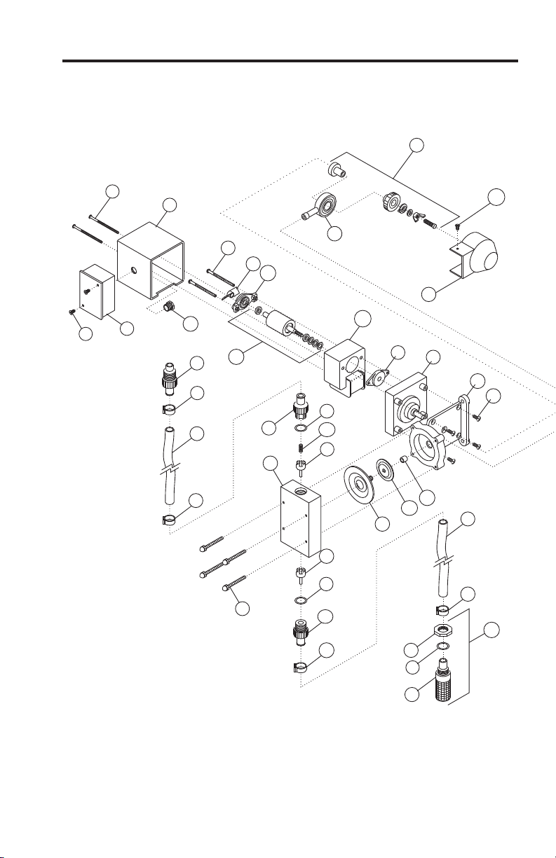
Page 13

4
4
10
9
8
22
6
3
5
15
28
16
15
14
13
26
27
12
11
23
25
25
T.I. Anti siphon valve
fitting
Threaded Anti siphon
valve, ¼ & ½” N.P.T.
Optional
7
2
3
1
17
18
19
20
24
21
Exploded View
C-600P
Page 13
Page 14

CCatalog No. Description Amount Reqd.
1. C-395-6V Injection valve 6 PSI, Viton 1
C-395-6E Injection v
alve 6 PSI, EP (optional) 1
2. C-335-6 Discharge Tubing 3/8 OD, 5ft. Opaque Poly-E 1
3. C-330-6 Tube Nu
t 2
4. K-568V-4 Bullet valve (double ball), Viton, 4 pack set 2
K-568V-10 bullet valve (double ball
), Viton, 10 pack set 2
K-569E-4 Bullet valve (double ball), EP, 4 pack set (optional) 2
K-569
E-10 Bullet valve (double ball), EP, 10pack set(optional) 2
5. C-334-6 Suction tubing 3/8’ OD, 5ft. Cle
ar PVC w/ indicator 1
6. C-346 Ceramic weight 1
7. C-345V Foot valve / strainer Poly-Pro, Viton 1
C
-345E Foot valve / strainer Poly Pro, EP (optional) 1
8. C-535 Heavy duty molded pump head 1
9. C-504HD
Screw, HD Pump head 10-32 x 1-1/4’ 4
10. C-535FC Pump head cover, Chem feed logo 1
11. C-628 Cover screw 6
-32 x 2-3/4’ Steel 2
12. C-608P Motor Cover 1
13. C-625 Motor screw 8-32 x 2-1/2’ 2
14. C-612F Rotor Fan 1
15. C
-612PB Rotor Bearing 2
16. C-616PN Rotor w/ Spacer 1
17. C-618P-14 Gearbox Assembly, 14 RPM 1
C-618P-30
Gearbox Assembly, 30 RPM 1
C-618P-45 Gearbox Assembly, 45 RPM 1
C-618P-60 Gearbox Assembly, 60
RPM 1
C-618P-125 Gearbox Assembly, 125 RPM 1
C-618P-250 Gearbox Assembly, 250 RPM 1
18. C-301 Moto
r Mount 1
19. C-624 Motor Mount Screw 10-32 x ½’ 4
20. C-325 Cam S/A C-600 1
21. C-304 Yoke w/Bearings 1
22. C-4
06T Diaphragm PTFE coated, EP 1
23. 90011-155 Screw 6-332 x 3/8’ 1
24. 90002-201 Cam Cover 1
25. C-550-6V Bull
et Valve Adapter, Viton O-ring 2
C-560-6E Bullet Valve Adapter, EP O-ring 2
26. 90007-515 ½” Alumin
um Chase Nipple 1
27. C-308J Junction Box Complete w/Cover and Gasket 1
28. C-615P-1 Stator S/A 115V/60Hz,
blue-black (lead wires) 1
C-615P-2 Stator S/A 230V/60Hz, red-black (lead wires) 1
C-615P-3 Stat
or S/A 220V/50Hz, brown-blue (lead wires) 1
C-615P-4 Stator S/A 24V/60Hz, blue-white (lead wires) 1
C-615P-6 Stator S/A 230V/60Hz, red-yellow (lead wires) 1
C-615P-8 Stator S/A 220V/50Hz, brown
-yellow (lead wires) 1
C-615P-9 Stator S/A 115V/60Hz, blue-yellow (lead wires) 1
C- 600P Parts List
Page 14
Page 15

LIMITED WARRANTY
Your new pump is a quality product and is warranted to be free of defects as set down in this policy. All parts, including
rubberized goods, and labor are covered under warranty for 90 days from the date of purchase. Used peristaltic pump tube
assemblies are not warranted. Parts, excluding rubberized goods, are covered under warranty for 12 months from the date
of purchase.
Warranty coverage does not include damage to the pump that results from misuse, carelessness, abuse or alteration. Only
the repair or the replacement of the pump is covered. Blue-White Industries does not assume responsibility for any other
loss or damage.
Warranty status is determined by the pump’s serial label and the sales invoice or receipt. The serial label must be on the
pump and the pump must be accompanied by the sales invoice or receipt to obtain warranty coverage. The warranty status
of the pump will be verified by Blue-White or a factory authorized service center.
Please be advised; injection and metering devices are not intended as a means of treating water to render it suitable for
human consumption. When used as hypochlorinators, they are meant to destroy bacteria and algae contamination, before
it’s removal by filtration. Acid and soda injectors are used for PH control (balance). Blue-White injectors are factory tested
with water only for pressure and performance. Installers and operators of these devices must be well informed and
aware of the precautions to be taken when injecting various chemicals -especially those considered hazardous or
dangerous.
Should it become necessary to return an injector for repair or service, you must attach information regarding the chemical
used as some residue may be present within the unit which could be a hazard to service personnel.
Blue-White Industries will not be liable for any damage that may result by the use of chemicals with their injectors and it’s
components. Thank you.
PROCEDURE FOR IN WARRANTY REPAIR
Carefully pack the pump to be repaired, include the foot strainer and injection/check valve fitting. Enclose a brief description
of the problem as well as the original invoice or sales receipt showing the date of purchase. The receipt will be returned
with the unit. Prepay all shipping costs. COD shipments will not be accepted. Warranty service must be performed by the
factory or an authorized service center. Damage caused by improper packaging is the responsibility of the sender.
AUTHORIZED SERVICE CENTERS
ARKANSAS Picard Chemical
BT Environmental, Inc 1670 S. Congress Avenue Shelter’s Water Refining
Bill Thomason W. Palm Beach, FL 33406 Robert Shelton
225 Castleberry Street 561-965-3434 2708 E. Randol Mill Rd.
Hot Springs, AR 71901 Arlington, TX 76011
501-624-3837 ILLINOIS 817-640-6188
Mullarkey Associates
CALIFORNIA (NORTHERN)
(Repair Center)
Howard E. Hutching company
12346 S. Keeler Ave.
(Repair Center)
Alsip, IL 60658
7190 Penryn Plaza
708-597-5558
Penryn, CA 95663
800-568-3958
MARYLAND
Swimco Electric Co. Century Pool Service, Inc
753 Camden Avenue 5020 Nicholson Court, #201
Campbell, CA 95008 Kensington, MD 20895
408-378-2607 301-231-8999
CALIFORNIA (SOUTHERN)
NEW YORK
Blue-White Industries
Sherwood Specialties, Inc.
(Repair Center)
875 Atlantic Ave. ‘B’
5300 Business Drive
Rochester, NY 14609
Huntington Bch. CA 92649
585-546-1211
714-893-8529
COLORADO
NORTH CAROLINA
Denver Winpump
Southern Industrial Sales
5754 Lamer ave
1903 Herring Avenue
.Arvada, CO 80002
Wilson, NC 27893
303-424-3551
800-872-7665
CONNECTICUT
SOUTH DAKOTA
Cronin-Cook & Associates
Son-Aqua Distributing
24 West Road
Jim Robinson
Vernon, CT 06029
2447 W. Main Street
860-875-0544
Rapid City, SD 57702
Rice Pump & Motor Repair 605-343-7716
5740 Powerline Road
Ft. Lauderdale FL 33309
TENNESSEE
954-776-6049
Rock City Machine
307 3rd Avenue South
American Pump
Nashville, TN 37201
7580-A W. Tennessee St.
615-244-1371
Tallahassee, FL 32304
850-575-9618
Jerry Lee Chemical Co.
TEXAS
3407 W. Old Fairfield Drive
Alamo Water Refiners
Pensacola, FL 32505
13700 Hwy. 90 West
904-432-9929
San Antonio, TX 78245
210-677-8400
Page 16

Users of electrical and electronic equipment (EEE) with the WEEE marking per Annex IV of
the WEEE Directive must not dispose of end of life EEE as unsorted municipal waste, but
use the collection framework available to them for the return, recycle, recovery of WEEE
and minimize any potential effects of EEE on the environment and human health due to the
presence of hazardous substances. The WEEE marking applies only to countries within the
European Union (EU) and Norway. Appliances are labeled in accordance with European
Directive 2002/96/EC.
Contact your local waste recovery agency for a Designated Collection Facility in your area.
Rev.09/18/2012# 80000-017
 Loading...