

Page 1

INJECTOR
MODEL C-1100
POSITIVE DISPLACEMENT INJECTOR PUMP
OPERATING MANUAL
Models C-1100A, C-1100C, C-1100F, C-1100X
R
Blue- White
PT SARANA PRIMA ENGUNA
Jl.Gunung Sahari Raya 84 C
Pho ne: 021 4200045 Fax : 021 4200483
Jakarta - 10610
Web sit e: w ww . sp e.c o.i d
Page 2

Page 2 C-1100
TABLE OF CONTENTS
1.....Introduction.....................................................................................3
2.....Specifications...................................................................................3
3.....Features ...........................................................................................3
4.....Unpacking .......................................................................................4
5.....Installation.......................................................................................4
5.1 ..Mounting location .....................................................................4
5.2..Optional circuit board signal connection installation.................6
5.3. .Input power connections ..........................................................8
5.4..Howto install the tubing and fittings .........................................10
6.....How to operate the Pump...............................................................11
6.1 ..How to adjust the output - manual stroke adjustment...............11
6.2..Fixed cycle timer models ..........................................................12
6.3..Variable speed model ................................................................ 12
6.4..FVS -Flow Verification System ................................................13
7.....How to maintain the Pump.............................................................14
7.1 ..Routine inspection and cleaning................................................14
7.2..Howto clean the pump .............................................................. 14
7.3 ..Measuring the pump output - Volumetric test...........................14
Pump head and Valve exploded view drawing .............................15
Replacement parts drawing............................................................16
Replacement parts list.....................................................................17
Warranty information ....................................................................18
Page 3

C-1100
1.0 Introduction
Congratulations on purchasing the C-1100 Model-E positive displacement
Metering Pump. The C-1100 is designed to inject chemicals into piping
systems and is capable of injecting against system pressures up to 150 PSI
(10.4 bar). In addition to the front mounted mechanical flow rate adjustment, the C-1100A and C-1100C models include timer circuitry, and C1100F includes speed control circuitry designed to adjust the pump’s output.
This manual covers models with the following feed rate mechanisms:
1. Fixed Cycle Timer & Mechanical Stroke Length - (Models C-1100A
and C-1100C) The fixed speed pumping mechanism is turned on and off by
an electronic timer. The total cycle time is factory set. The on-time cycle is
adjustable from 5% through 100% of the total cycle time. Model C-1100A
has a 60 second cycle with a 60 second adjustable on-time. Model C-1100C
has a 5 second cycle with a 5 second adjustable on-time.
2. Variable Speed Controller & Mechanical Stroke Length - (Model C1100F) The speed of the pumping mechanism is adjustable from 5%
through 100%.
3. Mechanical Stroke Length - (Model C-1100X) Mechanical adjustment only.
2.0 Specifications
Maximum Working Pressure 150 psig / 10.4 bar (most models)
Maximum Fluid Temperature 130 F / 54 C
Ambient Temperature Range 14 to 110 F / -10 to 43 C
Duty Cycle Continuous
Maximum Viscosity 1,000 Centipoise
Maximum Suction Lift up to 30 ft. water
Power Requirements 115V60Hz 80 Watts,
Dimensions 6-1/4” H x 10-1/8” W x 9” D
Weight 8 lb. / 3.6 Kg
o o
o o
220V50Hz 40 Watts,
230V60Hz 45 Watts
Page 3
3.0 Features
!
Double-ball, springless ceramic check valves with PVDF (Kynar) body,
TFE/P (Aflas) and Viton o-ring seals.
!
Easy access, front mounted mechanical feed rate adjustment.
!
High outlet pressure capability of 150 psig (most models)
!
Easy to adjust cycle timer or electronic motor speed control.
!
400:1 adjustment turn down ratio. (Model C-1100X turndown 20:1)
!
Corrosion proof Valox housing.
!
Tamper resistant electronic control panel cover.
Page 4

Page 4
CAUTION: Proper eye and skin protection must be
worn when installing and servicing the pump.
C-1100
4.0 Unpacking
Your pump package should contain the following:
1 - Injector pump
1 - Suction tube footvalve & strainer assembly
1 - Ceramic tubing weight
1 - 5’ Length of clear PVC suction tubing
1 - 5’ Length of opaque LLDPE discharge tubing
1 - Injection fitting with internal back-flow check valve
1 - Mounting hardware kit
5.0 Installation
CAUTION: Proper eye and skin protection must be
worn when installing and servicing the pump.
ø Note: All diagrams are strictly for guideline purposes only. Always consult
an expert before installing the pump into specialized systems. The pump
should be serviced by qualified persons only.
5.1 Mounting Location
Choose an area located near the chemical supply tank, chemical injection
point and electrical supply. Although the pump is designed to withstand
outdoor conditions, a cool, dry, well ventilated location is recommended.
Install the pump where it can be easily serviced.
!
Mount the pump to a secure surface or wall using the enclosed hardware.
Wall mount to a solid surface only. Mounting to drywall with anchors is not
recommended.
!
Mount the pump close to the injection point. Keep the outlet (discharge)
tubing as short as possible. Longer tubing increases the back pressure at the
pump tube.
!
Your solution tank should be sturdy. Keep the tank covered to reduce
fumes. Do not mount the pump directly over your tank. Chemical fumes
may damage the unit. Mount the pump off to the side or at a lower level
than the chemical container.
!
Mounting the pump lower than the chemical container will gravity feed the
chemical into the pump. This “flooded suction” installation will reduce
output error due to increased suction lift. You must install a shut-off valve,
pinch clamp or other means to halt the gravity feed to the pump during
servicing.
!
Be sure your installation does not constitute a cross connection with the
drinking water supply. Check your local plumbing codes.
Page 5
C-1100
Page 5
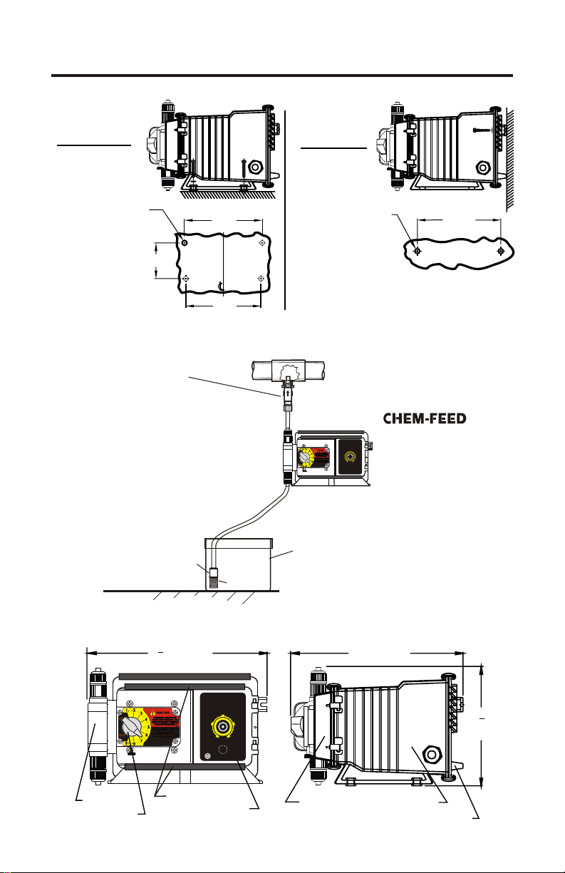
INJECTOR MOUNTING
Floor Mount
Drill .156 Dia. (5/32)
For Self-Tap Screw
#10 X 1” Phillips Steel
4 Places
Injection / Check valve
with 1/4” and 1/2” male
pipe threads.
Mount in upward position
to prevent trapped gasses
in the injection fitting.
Ceramic Weight
7-5/8”
3-1/2”
7-3/8”
TYPICAL INSTALLATION
Discharge
Tube
Suction
Tube
Strainer
Wall Mount
Drill .156 Dia. (5/32)
For Self-Tap Screw
#10 X 1” Phillips Steel
2 Places
Note: For wall-mounting, drill & thread into
solid wood only.
Wall or shelf mount
A-100N
50%
away from the top of the
25%
75%
100%
0%
solution tank. Chemical
ON OFF
O
I
fumes can damage the
unit.
Chemical
Container
with cover
8-3/16”
®
Pumphead
Adjustment knob
1
9 IN. (235 MM)
4
Slide Clamps*
Electronic Control
PARTS LOCATOR DRAWING
50%
25%
75%
100%
0%
ON OFF
L
A
I
T
U
Y
Q
O
I
P
T
R
BLUE-WHITEINDUSTRIES
C
O
U
D
Control Cover
10 IN. (254 MM)
Motor Housing
Rear Cover
(159
1
6
IN.
4
MM)
Page 6

Page 6
C-1100
5.2 Optional circuit board signal connection installation - The
pump includes three optional external signal connections:
!
FVS - FLOW VERIFICATION SENSOR INPUT
Accepts a pulse signal from an optional Blue-White sensor confirming that
fluid is passing through the pump. Triggers and alarm output if fluid is not
detected.
!
AL - ALARM OPEN COLLECTOR OUTPUT
The output (purple wire) sinks to DC ground when an alarm condition
exists. 6-30Vdc collector voltage. 50mAdc maximum sinking current.
!
MA - MOTOR ACTIVE OPEN COLLECTOR OUTPUT
The output (brown wire) sinks to DC ground when the motor is deenergized. 6-30Vdc collector voltage. 50mAdc maximum sinking current.
All signal wires must be connected to the circuit board, located inside the
pump enclosure, using connector plug wiring assemblies. A liquid-tight
connector must be installed in the pump enclosure wall and the signal wires
passed through the liquid-tight connector and secured. See pages 8 & 9 for
wiring details.
1. Remove the rear enclosure panel.
2. Remove knock-out using a screwdriver.
3. Trim edge with a knife and remove sharp edges.
4. Install the provided liquid-tight connector.
5. Connect the connector plug to the circuit board.
1/2” DIAMETER KNOCKOUT
LIQUID-TIGHT CONNECTOR
Page 7

C-1100
CIRCUIT BOARD SIGNAL CONNECTION
FVS - FLOW VERIFICATION
SENSOR INPUT
Page 7
T3
T4
230VAC
T2
T1
120 VAC
HOT
LOAD
-+-
MA AL
TFD
FVS
-
++
-
SIG
+
AL - OPEN COLLECTOR
ALARM OUTPUT
MA - OPEN COLLECTOR
MOTOR ACTIVE OUTPUT
Page 8

Page 8
WARNING: Risk of electric shock.
C-1100
5.3 Input Power Connections
WARNING: Risk of electric shock.
Be certain to connect the pump to the proper supply voltage. Using the
incorrect voltage will damage the pump and may result in injury. The
voltage requirement is printed on the pump serial label.
The pump is supplied with either a ground wire conductor and a grounding
type attachment plug (power cord) or a junction box for field wiring.
POWER CORD MODELS -To reduce the risk of electric shock, be certain
that the power cord is connected only to a properly grounded, grounding
type receptacle.
JUNCTION BOX MODELS -To reduce the risk of electric shock, be
certain that a grounding conductor is connected to the green grounding
conductor located in the junction box.
Note: When in doubt regarding your electrical installation, contact a
licensed electrician.
MOTOR LEADWIRES
INPUT
VOLTAGE
115VAC 60Hz
220VAC 50Hz
230VAC 60Hz
90VDC
HOT
LEADWIRE
YELLOW
YELLOW
YELLOW
(+) RED
NEUTRAL
LEADWIRE
BLUE
BROWN
RED
(-) BLACK
GROUND
LEADWIRE
GREEN
GREEN
GREEN
GREEN
CIRCUIT BOARD SIGNAL IN/OUT CONNECTIONS
SYSTEM DESCRIPTION
FVS - FLOW VERIFICATION SENSOR INPUT
Accepts a pulse signal from an optional Blue-White sensor
confirming that fluid is passing through the pump.
Triggers and alarm output if fluid is not detected.
TFD - TUBE FAILURE DETECTION SYSTEM INPUT
Monitors a pair of sensors in the pumphead. Triggers an alarm
output if fluid with a conductivity of greater than 500 micro-seimens
is detected. Typical chemicals include chlorine, acid, caustic.
The system will not detect water or silicone lubricating oil.
AL - ALARM OPEN COLLECTOR OUTPUT
The output (purple wire) sinks to DC ground when an alarm
condition exists.
6-30Vdc collector voltage. 50mAdc maximum sinking current.
MA - MOTOR ACTIVE OPEN COLLECTOR OUTPUT
The output (brown wire) sinks to DC ground when the motor is
de-energized.
6-30Vdc collector voltage. 50mAdc maximum sinking current.
WIRE COLOR CODE
RED (+ 20VDC)
BLACK (-)
YELLOW (signal)
GRAY & GRAY
PURPLE (+) & BLACK (-)
BROWN (+) & BLACK (-)
Page 9

C-1100
OPTIONAL POWER
INDICATOR LAMP
COMMON
AC
INPUT
AC
INPUT
HOT
GROUND
OPTIONAL POWER
INDICATOR LAMP
COMMON
HOT
GROUND
CYCLE ADJUSTMENT
POTENTIOMETER
AC
MOTOR
POWER
SWITCH
NEUTRAL
108/130 VAC
208/240 VAC
OPTIONAL INJECTOR
INDICATOR LAMP
T4
230VAC
T2
T1
T3
120 VAC
HOT
LOAD
-+-
MA AL
PURPLE
(+)
+
HOT
WIRING DIAGRAM - Model A-100NA & A-100NC
CYCLE ADJUSTMENT
POTENTIOMETER
AC
MOTOR
PRIME
SWITCH
NEUTRAL
HOT
108/130 VAC
208/240 VAC
OPTIONAL INJECTOR
INDICATOR LAMP
T4
230VAC
T2
T1
T3
120 VAC
HOT
LOAD
-+-
MA AL
PURPLE
(+)
+
TFD
-
++
BLACK
(-)
TFD
-
++
BLACK
(-)
FVS
FVS
Page 9
-
SIG
-
SIG
AC
INPUT
OPTIONAL POWER
INDICATOR LAMP
COMMON
HOT
GROUND
DC
MOTOR
WIRING DIAGRAM - Model A-100NS
NOTCH LOCATION INDICATES
INPUT POWER REQUIREMENT
108/130 VAC
208/240 VAC
WHITE
YELLOW
POWER
SWITCH
BLACK
RED
(-) Vdc
(+) 90 Vdc
WIRING DIAGRAM - Model A-100NF
SPEED ADJUSTMENT
POTENTIOMETER
TFD
-
++
-+-
+
MA AL
PURPLE
BLACK
(+)
(-)
FVS
-
SIG
Page 10

Page 10
CAUTION: Proper eye and skin protection must be
worn when installing and servicing the pump.
C-1100
5.4 How To Install the Tubing and Fittings
CAUTION: Proper eye and skin protection must be
worn when installing and servicing the pump.
! Inlet Tubing - Locate the inlet fitting of the pump head. Remove the tube
nut. Push the clear suction tubing through the tube nut and onto the fitting
barb. Hand tighten the tube nut to secure the tubing.
! Footvalve/Strainer - Trim the inlet end
of the suction tubing so that the strainer
will rest approximately two inches from
the bottom of the solution tank. This will
prevent sediment from clogging the
strainer. Slip the ceramic weight over
the end of the suction tube. Press the
strainer’s barbed fitting into the end of
the tube. Secure the ceramic weight to
the strainer. Drop the strainer into the
solution tank.
! Outlet Tubing - Locate the outlet
fitting of the pump head. Remove the
tube nut. Push the opaque discharge
tubing through the tube nut and onto the
compression barb of the fitting. Hand
tighten the tube nut to secure the tubing.
Keep outlet tube as short as possible.
! Injection/Check Valve Fitting
Installation - The Injection/Check valve
fitting is designed to install directly into
either 1/4” or 1/2” female pipe threads.
This fitting will require periodic
cleaning, especially when injecting
fluids that calcify such as sodium
hypochlorite. See section 7.0.
Install the Injection/Check valve directly
into the piping system. To prevent
trapped gasses, install the fitting in an
upward direction. Use Teflon thread
sealing tape on the pipe threads.
Push the opaque outlet (discharge)
tubing through the tube nut and onto the
compression barb of the Injection/Check
valve fitting. Hand tighten the tube nut
to secure the tubing.
FOOTVALVE/STRAINER
Suction Tubing
Ceramic
Wei ght
FootValve
Strainer
Assembly
INJECTION/CHECK VALVE
Pipe tee
Install
upward
Injection
Check valve
Tube retaining
nut
Discharge
Tubing
Page 11

C-1100
Page 11
Injection
Check valve
Tub e N ut
Discharge Tube
(Rigid P.E.)
Tub e N ut
Outlet Adapter
Pump Head
Inlet Adapter
Tub e N ut
Suction Tubing
(clear PVC)
Ceramic Weight
Footvalve
Install
upward
Manual
Stroke length
Adjustment knob
Lock Screw
25%
50%
0%
ON OFF
I
75%
100%
O
6.0 How To Operate The Pump
6.1 How to adjust the output- manual stroke adjustment The
Pump flow rate can be adjusted within a range of 5% -100% of maximum
output (20:1 turndown ration) by means of a mechanical, cam type
mechanism. The mechanism adjusts the pump’s stroke length to an infinite
number of settings within the flow range.
ø Note: The pump’s output will reduce due to increased system pressure,
increased suction lift, and increased fluid viscosity. The pump must be oversized to allow for these factors. Sizing the pump to allow adjustment within
the midrange is preferred to maintain accuracy. Consult the factory for
individual pump model output curve data.
To adjust the pump’s output:
1. With the pump running, loosen the lock screw.
2. Turn the adjustment knob to the desired setting.
3. Re-tighten the lock screw.
Page 12

Page 12
C-1100
6.2 Fixed Cycle Timer Models -The pumping
mechanism is turned on and off by an electronic
cycle timer. The total-time cycle is factory preset
50%
and is not user adjustable. The on-time cycle is
adjustable from 5% to 100% of the total cycle
25%
time. Example: If the total-time cycle is 60
seconds and the on-time cycle is adjusted for 25
100%
percent, the pump will run for 15 seconds and turn
0%
off for 45 seconds (60 second total cycle). This
cycle is repeated until either the power switch is
turned off, the cycle time is changed or the input
ON OFF
O
I
power is disconnected from the pump.
To adjust the pump output -
!
Slide the slide clamps to the left only far enough to open the control panel
door.
!
Turn the adjustment knob to the desired percentage of on-time per cycle.
ø
Note: When power is applied to the pump, the pump will either
automatically begin to pump, or maintain power-off status, depending
on the power switch status.
6.3 Variable Speed Model -The speed of the pumping mechanism is
adjustable from 5 % through 100%.
To adjust the pump output -
!
Slide the slide clamps to the left only far enough to open the control panel
door.
!
Turn the adjustment knob to the desired percentage of speed.
75%
DIGITALTIMER PUMP
MODE
1
VDC
mA Hz
1000
ON-T
TOT-TSECMINHR DAY
ALARM
TFD
FVS
SERVICE
DIGIT MODE
FIELD
RUN
STANDBY
PRIME
DISPLAY
RESETSERVICE
PROGRAM
INPUTMODES
2- 4-20mA
1- MANUAL
4- 0-1000 Hz
5-PULSE(BATCH)
SLIDE CLAMP
RUN
PROGRAM
STAND-BY
PRIME
MINIMUM
MAXIMUM
3- 0-10VDC
Page 13

OPERATING
FLOW RANGE
(ml/min)
C-1100
Page 13
6.4 (FVS) Flow Verification System The pump is equipped with a
-
Flow Verification System which is designed to stop the pump and provide
an open collector (sinking) output signal in the event the sensor does not
detect chemical during pump operation. This could indicate a clogged
injection fitting, empty chemical solution tank, loose tubing connection, etc.
The system features an alarm delay time of 6 seconds which allows the
pump to clear any gasses that may have accumulated during stopped
operation. The pump will stop, and the alarm mode activated, if no pulses
are received by the pump and the alarm delay time period has ended. Turn
the power switch off and on to clear the alarm and restart the pump. The
Flow Verification Sensor is sold as an optional accessory.
Confirm the FVS flow range - The Flow
Verification Sensor (FVS) will only function
within its operating range. Sensor model
FV-100-6V has an operating range of 30300 ml/min (1-10 oz/min). If the pump’s
output is less than 30 ml/min (0.5 ml/sec),
the sensor will not detect chemical and a
signal will not be sent to the pump.
SENSOR
MODEL
NUMBER
FV-100-6V
FV-200-6V
FV-300-6V
FV-400-6V
FV-500-6V
FV-600-6V
OPERATING
FLOW RANGE
(ml/min)
30-300
100-1000
200-2000
300-3000
500-5000
700-7000
Install the FVS Flow Sensor - The Flow Verification Sensor (FVS) should
be installed on the outlet (discharge) side of the pump head valve. The
sensor includes a PVC tubing insert, located inside the sensor’s female
thread connection, that is designed to seal the sensor onto the pump tube
inlet adapter. Thread the sensor onto the pump tube until the tubing insert is
snug against the pump tube inlet fitting - do not over-tighten.
Connect the red/white (+), black (-),
and bare (signal) wires from the
sensor to the red (+), black (-), and
yellow (signal) wires on the plug
connector. Knock-out the liquid-tite
connector mounting hole on the
side of the pump enclosure and
FVS Sensor
Insert Tubing Seal
install the liquid tight connector.
Route the wires through the
Outlet Adapter
connector and tighten the connector
nut. Plug the connector onto the
circuit board at the pins marked
“FVS”. See page 6.
Open Collector Alarm Output -
An open collector (sinking) output
signal is provided with the FVS
DIGITALTIMER PUMP
MODE
1
1000
ON-T
TOT-TSECMINHRDAY
TFD
FVS
FIELD
RUN
STANDBY
PRIME
RESETSERVICE
INPUTMODES
1-MANUAL
4-0-1000 Hz
RUN
PROGRAM
VDC
mA Hz
STAND-BY
PRIME
MINIMUM
ALARM
SERVICE
MAXIMUM
DIGIT MODE
DISPLAY
PROGRAM
3-0-10VDC
2-4-20mA
5-PULSE (BATCH)
system. (See page 6).
Page 14

Page 14
CAUTION: Proper eye and skin protection must be
worn when installing and servicing the pump.
C-1100
7.0 How to Maintain the Pump
CAUTION: Proper eye and skin protection must be
worn when installing and servicing the pump.
7.1 Routine Inspection and Maintenance
The pump requires very little maintenance. However, the pump and all
accessories should be checked regularly. This is especially important when
pumping chemicals. Inspect all components for signs of leaking, swelling,
cracking, discoloration or corrosion. Replace worn or damaged components
immediately.
Cracking, crazing, discoloration and the like during the first week of
operation are signs of severe chemical attack. If this occurs, immediately
remove the chemical from the pump. Determine which parts are being
attacked and replace them with parts that have been manufactured using
more suitable materials. The manufacturer does not assume responsibility
for damage to the pump that has been caused by chemical attack.
7.2 How to Clean the Pump
The pump will require occasional cleaning, especially the Injection fitting,
the Footvalve/Strainer, and the pump head valves. The frequency will
depend on the type and severity of service.
]
Inspect and replace the pumphead valves as required.
]
When changing the diaphragm, the pump head chamber and pump head
cover should be wiped free of any dirt and debris.
]
Periodically clean the injection/check valve assembly, especially when
injecting fluids that calcify such as sodium hypochlorite. These lime
deposits and other build ups can clog the fitting, increase the back pressure
and interfere with the check valve operation. See page 8.
]
Periodically clean the suction strainer. See page 8.
]
Periodically inspect the air vents located under the motor housing and in
the back on the rear housing cover. Clean if necessary.
7.3 Measuring the Pump’s Output - Volumetric Test.
This volumetric test will take into account individual installation factors
such as line pressure, fluid viscosity, suction lift, etc. This test is the most
accurate for measuring the injector’s output in an individual installation.
1. Be sure the Injection Fitting and Footvalve/Strainer is clean and working
properly.
2. Fill a large graduated cylinder with the solution to be injected.
3. With the pump installed under normal operating conditions, place the
suction tubing with the Footvalve/Strainer installed in the graduated
cylinder.
4. Run the pump until all air is removed from the suction line and the solution
Page 15

C-1100
enters the discharge tubing. If the pump does not easily prime, remove the
discharge tubing from injection fitting until the pump primes. Re-connect
the discharge tubing to the injection fitting.
5. Remove the suction tubing from the graduated cylinder and refill the
graduated cylinder if necessary. Note the amount of solution in the graduated cylinder.
6. Place suction tubing with the Footvalve/Strainer installed back into the
graduated cylinder.
7. Run the injector for a measured amount of time. A longer testing time will
produce more accurate results.
8. Remove the suction tubing from the graduated cylinder. Measure the
amount of chemical injected.
Page 15
PUMP HEAD AND VALVE EXPLODED VIEW
Page 16

Page 16
43
38
40
C-1100
REPLACEMENT PARTS DRAWING
63
62
69
41
42
61
60
64
37
52
51
36
55
54
56
35
39
59
38
32
31
58
57
34
30
33
29
28
70
21
20
16
19
18
27
26
49
48
24
47
25
22
23
45
5
68
67
66
65
53
52
51
50
%75
%
OFF
00
O
1
%5
0
I
%
0
N
O
%
5
2
46
44
3
4
9
17
15
14
12
11
13
10
8
6
7
2
1
Page 17

C-1100
Page 17
REPLACEMENT PARTS LIST
Item Part No Description Qty
Item Part No Description Qty
76001-035 Enclosure, J-box model 1
32 76001-183 Motor Mount, Large Dia 1
90010-196 Power Cord, 220v50 1
90010133 Power Cord, 230v60 1
A-023N-H Timer 5 sec. Model C 1
C-1817N-1 Speed control 115V model F 1
C-1817N-4 Speed control 220V model F 1
C-1817N-5 Speed control 230V model F 1
50 90003-559 Mounting Feet, Rubber 4
51 90011-091 Screw, #10 X 1.0” Phl ST 6
52 90011-094 Washer, #10 Stainless 6
53 90010-110 Power Cord, 115v60 1
54 70000-589 Connector Liq-tite w/ nut .375 1
56 A-023N-B Timer 60 sec. Model A 1
70000-682 Diaph. S/A 2.0 15N, EP/TFE 1
71000-358 Gearbox, 30 RPM 1
71000-359 Gearbox, 45 RPM 1
71000-360 Gearbox, 60 RPM 1
71000-361 Gearbox, 125 RPM 1
71000-362 Gearbox, 250 RPM 1
33 70000-683 Diaph. S/A 2.0 15N, Vit/TFE 1
34 71000-357 Gearbox, 14 RPM 1
57 90011-146 Screw, 8-32 X .25 Phil Pan F 1
58 90006-583 Motor Retaining Clip, Ss 1
59 90006-580 Gasket, Back , Neoprene 1
60 90010-036 Wire Nut, Blue 2
62 90002-192 Enclosure Back Plate, Valox 1
63 90011-044 Screw 6-32 x .37 Swag Form 1
64 90007-515 Bushing, J-Box Conn, Alum. 1
65 90008-199 Connector Liq-tite w/ nut .187 1
66 76001-168 J-Box, Ext. Input, Valox 1
67 90011-129 Screw, 6-32 X .25 Phil SS 2
68 71000-133 Cover, J-Box w/Gasket ,Label 1
69 70000-364 J-Box Assembly, Ext. Input 1
70 C-395N-6A Inj. Valve .5-.25 MptX.37od T 1
Gearmotor, 45 Rpm, 230v60 1
71000-213 Stator 220v Brwn-Wht/yell 1
71000-212 Stator 230v Red-White/Yellow 1
70002-205 Gearmotor, 30 Rpm, 115v60 1
70002-206 Gearmotor, 45 Rpm, 115v60 1
70002-207 Gearmotor, 60 Rpm, 115v60 1
70002-208 Gearmotor, 125 Rpm, 115v60 1
70002-209 Gearmotor, 250 Rpm, 115v60 1
70002-210 Gearmotor, 14 Rpm, 220v50 1
70002-211 Gearmotor, 30 Rpm, 220v50 1
70002-212 Gearmotor, 45 Rpm, 220v50 1
70002-213 Gearmotor, 60 Rpm, 220v50 1
70002-214 Gearmotor, 125 Rpm, 220v50 1
35 90011-078 Washer, , #8 Intrl/Star 1
36 90010-222 Lead Wire, ground, Green 1
37 90011-024 Screw 8-32 x .25 Hex SL ST 1
38 70000-028 Bearing Bracket With Bearing 2
39 71000-211 Stator 115v Blue-Wht/Yell 1
40 70000-027 Rotor With Shaft And Spacers 1
41 90011-022 Screw, 8-32 X 2.5” Phl Steel 2
42 70002-204 Gearmotor, 14 Rpm, 115v60 1
70002-215 Gearmotor, 250 Rpm, 220v50 1
70002-216 Gearmotor, 14 Rpm, 230v60 1
70002-217 Gearmotor, 30 Rpm, 230v60 1
70002-219 Gearmotor, 60 Rpm, 230v60 1
70002-220 Gearmotor, 125 Rpm, 230v60 1
70002-221 Gearmotor, 250 Rpm, 230v60 1
70002-218
90012-225 Label blank (model X) 1
43 90006-581 Fan, Motor, 2.25” Dia,Alum 1
44 90002-191 Door, Controls Cover 1
45 90006-579 Gasket, Front, Neoprene 1
46 90012-224 Label percent control 1
47 76000-999 Slide Clamp, Encl Front 2
48 76001-000 Slide Clamp, Encl Rear 2
49 90002-190 Enclosure, P/cord model 1
Item Part No Description Qty
90003-129 O-ring Seat, FootValve, E.P. 1
90003-015 O-ring, FootValve, E.P. 1
71000-325 FootValve S/A, C-340A, Aflas 1
1 90002-086 Screen, FootValve, P.P. 1
2 90002-214 Body, FootValve, PVDF 1
3 2-108A O-ring Seat, FootValve,Aflas 1
4 90008-062 Ball, FootValve, Ceramic 1
5 90003-014 O-ring, FootValve, Viton 1
6 90002-215 Adapter, FootValve, PVDF 1
7 71000-324 FootValve S/A, C-340E, EP 1
71000-205 Adapter S/A Bullet .37T EP 2
71000-224 Adapter S/A Bullet .37T Sil 2
8 90008-068 Ceramic weight, C-346 1
9 90008-116 Tubing Suction 3/8 x 5 FT 1
10 90002-077 Tube Nut, .37T, P.P. 2
11 71000-204 Adapter S/A Bullet .37T Vit 2
12 71000-195 Cartridge Valve S/A, D-Ball 2
70001-153 Kit P/Head HDN 37T E.P. P-P 1
90001-133 Offset Cam #2 .055” 1
90001-134 Offset Cam #3 .187” 1
90001-141 Offset Cam #4 .100” 1
13 90002-146 P/Head Noir Molded, P.P. 1
14 90011-141 Screw 10-32 x 1.25 4
15 70004-074 Cover P/Head, HD logo 1
16 70001-149 Kit P/Head HDN 37T V. P-P 1
17 76000-374 Tubing D/Charge, 3/8 x 10 FT 1
18 90001-132 Offset Cam #1 .125” 1
19 90006-006 Return Spring 2
20 90002-001 Slide Bearing 2
21 76000-172 Stirr-up 1
22 90002-017 Dial Knob 1
23 90011-168 Screw #6 x .62 PH oval ‘A’ 4
24 90011-121 Thumb Screw 6-32 x 1.125 1
25 71000-363 Cover Cam S/A C-1100 1
70000-133 Drive Cam S/A #2 .055” 1
70000-132 Drive Cam S/A #3 .187” 1
70000-722 Drive Cam S/A #4 .100” 1
26 90006-597 Gasket, Top Cover 1
27 90004-005 Bearing, Top Cover 1
28 90012-218 Label, Cam Cover 1
28 70000-131 Drive Cam S/A #1 .125” 1
29 90011-014 Spacer, Rotor 1
30 90011-122 Screw 10-32 x .50 PHL PAN 4
31 90008-138 Plug .312 Hole Black 1
Page 18

Page 18
LIMITED WARRANTY
Your new pump is a quality product and is warranted to be free of defects as set
down in this policy. All parts, including rubberized goods, and labor are covered
under warranty for 90 days from the date of purchase. Used peristaltic pump
tube assemblies are not warranted. Parts, excluding rubberized goods, are
covered under warranty for 12 months from the date of purchase.
Warranty coverage does not include damage to the pump that results from
misuse, carelessness, abuse or alteration. Only the repair or the replacement of
the pump is covered. Blue-White Industries does not assume responsibility for
any other loss or damage.
Warranty status is determined by the pump’s serial label and the sales invoice or
receipt. The serial label must be on the pump and the pump must be
accompanied by the sales invoice or receipt to obtain warranty coverage. The
warranty status of the pump will be verified by Blue-White or a factory
authorized service center.
Please be advised; injection and metering devices are not intended as a means of
treating water to render it suitable for human consumption. When used as
hypochlorinators, they are meant to destroy bacteria and algae contamination,
before it’s removal by filtration. Acid and soda injectors are used for PH control
(balance). Blue-White injectors are factory tested with water only for pressure
and performance. Installers and operators of these devices must be well
informed and aware of the precautions to be taken when injecting various
chemicals -especially those considered hazardous or dangerous.
Should it become necessary to return an injector for repair or service, you must
attach information regarding the chemical used as some residue may be present
within the unit which could be a hazard to service personnel.
Blue-White Industries will not be liable for any damage that may result by the
use of chemicals with their injectors and it’s components. Thank you.
C-1100
PROCEDURE FOR IN WARRANTY REPAIR
Carefully pack the pump to be repaired, include the foot strainer and
injection/check valve fitting. Enclose a brief description of the problem as well
as the original invoice or sales receipt showing the date of purchase. The receipt
will be returned with the unit. Prepay all shipping costs. COD shipments will
not be accepted. Warranty service must be performed by the factory or an
authorized service center. Damage caused by improper packaging is the
responsibility of the sender.
Page 19

R
Blue- White
PT SARANA PRIMA ENGUNA
Jl.Gunung Sahari Raya 84 C
Jakarta – 10610
Phn. 021 4200045 Fax. 021 4200483
www.spe.co.id
# 80000-363 Rev. 1/12/2006
 Loading...