

Bluesky SAT 6.5 Active Satellite Owner's Manual
SAT 6.5 Active Satellite
SUB 12 Active Subwoofer
Owner’s Manual for 2.1 (stereo) Application

Contents
blue sky SAT 6.5 Active Satellite & SUB 12 Active Subwoofer
Owners Manual for 2.1 (stereo) Applications Issue 1
Contents
Important Safety Instructions _ __ __ __ __ __ __ __ __ __ _ Page 3
1 Philosophy and Introduction _ __ __ __ __ __ _ Page 4
2 What is THXpm3® Certifi cation_ __ __ __ __ __ _ Page 4
3 Quick Setup _ __ __ __ __ __ __ __ __ __ __ __ _ Page 5
4 System Signal Connection Diagram _ __ __ __ _ Page 6
5 A Tour of Sat 6.5 _ __ __ __ __ __ __ __ __ __ _ Page 7
6 A Tour of Sub 12 _ __ __ __ __ __ __ __ __ __ _ Page 8
7 Expanded Setup Guide _ __ __ __ __ __ __ __ _Page 10
8 Cable and Wiring Specifi cations _ __ __ __ __ _Page 11
9 Technical Information _ __ __ __ __ __ __ __ __ _Page 12
10 Satellite Cabinet Dimensions _ __ __ __ __ __ _Page 13
11 Subwoofer Cabinet Dimensions _ __ __ __ __ _Page 14
12 Factory Service Instructions _ __ __ __ __ __ __ _ Page 15
13 Contact Details _ __ __ __ __ __ __ __ __ __ __ _ Page 15
Page 3
blue sky SAT 6.5 Active Satellite & SUB 12 Active Subwoofer
Owners Manual for 2.1 (stereo) Applications Issue 1
1 READ INSTRUCTIONS - Read all safety and operating instructions
before operating this product.
2. RETAIN INSTRUCTIONS - Retain these safety and operating
instructions for future reference.
3. HEED WARNINGS - Follow all warnings on this product and in the
operating instructions.
4. FOLLOW INSTRUCTIONS - Follow all operating and use
instructions.
5. ATTACHMENTS - Do not use attachments not recommended by the
product manufacturer as they may cause hazards.
6. WATER AND MOISTURE - Do not use this product near water - for
example, near a bathtub, washbowl, kitchen sink, or laundry tub; in
a wet basement; or near a swimming pool; and the like.
7. ACCESSORIES - Do not place this product on an unstable cart,
stand, tripod, bracket, or table. The product may fall, causing
serious injury to a child or adult, and serious damage to the product.
Use only with accessories recommended by the manufacturer,
or sold with the product. Any mounting of the product should
follow the manufacturer’s instructions and should use a mounting
accessory recommended by the manufacturer.
8. POWER SOURCE - This product should be operated only from the
type of power source indicated on the marking label. If you are
unsure of the type of power supply to your home, consult your
product dealer or local power company.
9. OVERLOADING - Do not overload wall outlets or extension cords
as this can result in a risk of fi re or electric shock.
10. LIQUID ENTRY - Never spill any liquid of any kind on the product.
11. SERVICING - Do not attempt to service this product yourself.
Opening or removing covers, including any over bottom or side
speaker drivers, may expose you to dangerous voltage or other
hazards. Refer all service to qualifi ed service personnel.
12. DAMAGE REQUIRING SERVICE - Unplug this product from the
wall outlet and refer servicing to qualifi ed personnel under the
following conditions:
a. When the power-supply cord or plug is damaged.
b. If liquid has been spilled, or objects have fallen into this
product.
c. If the product does not operate normally by following the
operating instructions. Adjust only controls that are covered
by the operating instructions as an improper adjustment of
other controls may result in damage and will often require
extensive work by a qualifi ed technician to restore the prod-
uct to its normal operation.
d. If the product has been dropped or damaged in any way.
e. When the product exhibits a distinct change in performance
- this indicates a need for service.
13. REPLACEMENT PARTS - When replacement parts are required be
sure the service technician has used replacement parts specifi ed
by the manufacturer or have the same characteristics as the original
part. Unauthorized substitutions may result in risk of fi re, electric
shock, or other hazard.
14. SAFETY CHECK - Upon completion of any service or repairs to
this product, ask the service technician to perform safety checks to
determine that the product is in proper operating condition.
15. HEAT - This product should be situated away from heat sources
such as radiators, heat registers, stoves, or other products that
produce heat.
Safety Instructions

Page 4
blue sky SAT 6.5 Active Satellite & SUB 12 Active Subwoofer
Owners Manual for 2.1 (stereo) Applications Issue 1
1. Philosophy&
Introduction
Blue Sky is a philosophy. We design each product to represent the highest
ratio possible of performance to cost, providing the highest value added to
our customers.
We will continually seek out opportunities to utilize the talent of the Blue
Sky team to realize this philosophy. Our customer’s value requirements
will always be our prime focus, and only those products that achieve our
performance value ratio will earn the right to carry the Blue Sky logo.
Sat 6.5 and SUB 12 represent the fi rst products built using this philosophy.
Ultra high quality, THX Approved studio monitors, with a price vs.
performance ratio that cannot be beat.
Why do leading industry professionals choose Blue Sky Bass-Managed
Monitoring Systems as their reference monitoring system?
1. Blue Sky Bass-Managed Monitoring Systems are truly
full-range!
Unlike most monitoring systems on the market today (even most
large dual 15” in wall studio monitors), only a bass-managed
system, like the SAT 6.5 / SUB 12, can deliver true full-range in-room
response (20Hz to 20Khz). This allows you to hear everything that
your digital recorder is recording, including many of the subsonic
artifacts that only a mastering engineer would typically be able to
detect.
2. Blue Sky Bass-Managed Monitoring Systems strictly adhere to
industry standards put forth by companies like THX® and
Dolby®.
Blue Sky believes that your monitoring system shouldn’t just sound
good, but that the mixes you create on these monitors should also
translate into other environments such as Consumer Audio Systems,
Consumer Home Theatres or even Commercial Cinemas.
3. Unlike many systems on the market, Blue Sky’s computer
optimized bass-management and crossover networks ensure
accurate and smooth transition from Subwoofer to Main
Monitor and smooth on and off axis frequency response...
We strongly believe that our monitoring systems need to be
unquestionably accurate and we therefore have our products,
measurements and data reviewed by an independent company
- Lucasfi lm’s THX Division. THX reviews and then approves that
we have met or exceeded all of their stringent standards for
professional monitoring systems under their pm3 program. Monitor
with confi dence!
Thank you for choosing Blue Sky!
2. What is THX pm3®
Certification?
Nearly two decades ago, George Lucas turned a passion for great sound
into the world’s most accepted and trusted solution for achieving it. The
standard was named THX, and, today, with hundreds of thousands of home
theatre customers and more than 3000 THX Certifi ed movie theatres enjoying
the benefi ts, the THX name has become nothing short of legendary. Simply
put: when it comes to premium sound, no other name so closely defi nes
quality for millions of movie-goers and home theatre enthusiast alike. THX
IS ONE OF A KIND.
Today, a new landscape is emerging. A landscape comprised of hundreds
of small, professional multi-channel facilities, whose need for differentiation,
expert technical and marketing support and a true, multi-channel standard is
becoming a competitive fact of life. Again, THX has a singular solution and
this time it is called THX pm3 Certifi cation.
Blue Sky International has designed SAT 6.5 and SUB 12 to conform to THX’s
rigorous standards and have been approved for use in THX pm3 Certifi ed
Studios. For information regarding THX pm3 Certifi cation, please visit the THX
website, www.thx.com, or contact Blue Sky International.
For information on this and other Blue Sky products visit the Blue Sky
website at www.abluesky.com or contact Blue Sky International (contact
details are on page 15).
Page 5
blue sky SAT 6.5 Active Satellite & SUB 12 Active Subwoofer
Owners Manual for 2.1 (stereo) Applications Issue 1
3. Quick Setup
1. Carefully remove the SAT 6.5 Active Satellite and the SUB 12 Active
Subwoofer from their respective packaging. Please make sure to
retain all packaging materials for future shipping requirements.
2. The SAT 6.5 and SUB 12 leave the Blue Sky factory fully calibrated.
With the gain controls set to the reference mark (which is at
12 o’clock on the gain control) on the subwoofer and monitor
speakers, a 200mV -7dBu pink noise signal, with a bandwidth of
500 to 2kHz, will yield 90dB SPL at 1 meter for the satellite. Because
most small monitoring rooms have some gain at low frequency
a good starting point for the subwoofer level is -3dB from the
reference position.
3. The SAT 6.5 and SUB 12 use XLR connectors. You will need a total
of four (4) XLR cables for a stereo monitoring confi guration (not
supplied).
4. The fi rst step in the installation process is to position the active
subwoofer. Although you have great fl exibility in where the active
subwoofer is positioned, a good starting point is centered between
the left and right satellite speakers. This could be under the
console, behind the console, etc.
5. Once the subwoofer is in position, connect two XLR cables from
the left and right monitor outputs on the mixing console or digital
workstation to the Left and Right inputs on the subwoofer. Then
connect the remaining two XLR cables to the left and right satellite
outputs of the subwoofer. You will connect these cables at the end
of Step 6. Please note that the SUB 12 has a sophisticated auto
mute circuit, which mutes the subwoofer’s active monitor outputs
when there is no audio signal present for 15 minutes. Please plug
in the power cord to the IEC connector on the subwoofer. Also set
the subwoofer Phase switch to “+” and the Mute switch to “Auto”.
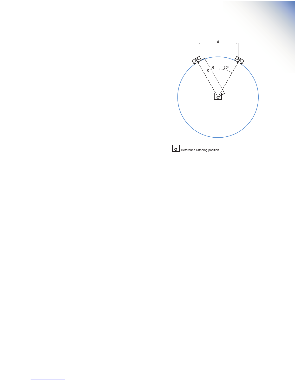
6. Next, place the SAT 6.5 Active Satellite Speakers into position. The
recommended position for the monitors is based on ITU standards
and sets the speakers at 60 degrees from the listener, forming
an equilateral triangle (a triangle with equal sides). See Figure 1.
Fortunately, this setup eliminates most of the math and is easily
simplifi ed to the following guidelines: If you want to sit 1 meter
(39.37 inches) from the speakers, place the speakers 1 meter apart.
If you want to sit 6 ft from the speakers, place the speakers 6 ft
apart. Etc. The active monitors can be positioned on the console,
on stands, etc. Ideally the SAT 6.5 active monitors should be at
seated ear height. If this is not possible, tilting the cabinet at the
listening area can improve high-frequency coverage.
7. Once the speakers are in position, plug the two XLR cables from
the Left and Right Subwoofer outputs into the SAT 6.5 inputs, and
then plug the power cord into the IEC connector on the SAT 6.5.
Confi rm the system is wired as shown in System Signal Connection
Diagram on - page 6.
8. At this point the Blue Sky monitoring system is correctly confi gured,
and ready for the fi nal step in the installation. Prior to plugging
the system into the wall, and powering up the system, do a quick
check of all connections.
9. If everything is correct, plug in all power cords. Do not turn on
the power switches, yet! Some mixers and out-board equipment
such as D-to-A converters and equalizers generate loud rail-to-rail
pops when they initially turn-on. Depending on the level and
the gain settings of the monitors, these pops could damage the
tweeters in the SAT 6.5 monitors. To avoid this, always turn on
equipment in the following sequence: Mixer 1st, subwoofer 2nd,
and satellite speakers last.
10. At this point the Blue Sky monitoring system is fully operational, and
ready for use. Begin by playing familiar pieces of music, which
can assist you in the fi ne-tuning and exact positioning of both the
active monitors and active subwoofer. It is important to remember
that the positioning of the subwoofer in the room will impact
the subwoofer level. You may fi nd it necessary to increase or
decrease the level from the reference position. This is OK, and is
anticipated.
11. If a more exacting setup is required, a pink noise generator, used in
conjunction with a real time analyzer can be used to fully optimize
the system (See Page 10 - Expanded Setup Guide).
12. Just remember - Use your ears, they are the best audio tool you
have and you will be amazed how accurate the setup can be if you
use familiar audio material during the setup of the system.
13. Congratulations! You have now completed the set up of one of
the world’s fi nest monitoring systems. If you have any questions,
please do not hesitate to contact us directly with your questions.
(631) 249-1399 (9:00am to 5:30pm EST)
 Loading...