

Page 1
bass management controller
bass management controller
owner's manual
BMC
Page 2

blue sky | BMC
Owner's Manual for 5.1 Applications Issue 1, rev 2
Contents
Important
1
2
3
4
5
6
7
8
9
10
11
12
13
Safety Instructions
Philosophy and Introduction
A Tour of the BMC Main I/O Unit
A Tour of the BMC Remote
System & Software Overview
5.1 Speaker Placement
5.1 System Wiring Diagram
5.1 System Calibration
Additional Setup Information
Cable and Wiring Information
Technical Information
Product Dimensions
Factory Service Instructions
Contact Details
Page 3
Page 4
Page 4
Page 5
Page 6
Page 7
Page 8
Page 9
Page 10
Page 10
Page 11
Page 11
Page 12
Page 12
Page 2
Page 3

Safety Instructions
blue sky | BMC
Owner's Manual for 5.1 Applications Issue 1, rev 2
1. READ INSTRUCTIONS - Read all safety and operating
instructions before operating this product.
2. RETAIN INSTRUCTIONS - Retain these safety and operating
instructions for future reference.
3. HEED WARNINGS - Follow all warnings on this product and
in the operating instructions.
4. FOLLOW INSTRUCTIONS - Follow all operating and use
instructions.
5. ATTACHMENTS - Do not use attachments not
recommended by the product manufacturer as they may
cause hazards.
6. WATER AND MOISTURE - Do not use this product near
water - for example, near a bathtub, washbowl, kitchen
sink, or laundry tub; in a wet basement; or near a
swimming pool; and the like.
7. ACCESSORIES - Do not place this product on an unstable
cart, stand, tripod, bracket, or table. The product may fall,
causing serious injury to a child or adult, and serious
damage to the product. Use only with accessories
recommended by the manufacturer, or sold with the
product. Any mounting of the product should follow the
manufacturer’s instructions and should use a mounting
accessory recommended by the manufacturer.
8. POWER SOURCE - This product should be operated only
from the type of power source indicated on the marking
label. If you are unsure of the type of power supply to
your home, consult your product dealer or local power
company.
9. OVERLOADING - Do not overload wall outlets or extension
cords as this can result in a risk of fire or electric shock.
11. SERVICING - Do not attempt to service this product
yourself.
Opening or removing covers, may expose you to
dangerous voltage or other hazards. Refer all service to
qualified service personnel.
12. DAMAGE REQUIRING SERVICE - Unplug this product from
the wall outlet and refer servicing to qualified personnel
under the following conditions:
a. When the power-supply cord or plug is
damaged.
b. If liquid has been spilled, or objects have fallen
into this product.
c. If the product does not operate normally by
following the operating instructions. Adjust only
controls that are covered by the operating
instructions as an improper adjustment of
other controls may result in damage and will
often require extensive work by a qualified
technician to restore the product to its normal
operation.
d. If the product has been dropped or damaged in
any way.
e. When the product exhibits a distinct change in
performance - this indicates a need for service.
13. REPLACEMENT PARTS - When replacement parts are
required, be sure the service technician has used
replacement parts specified by the manufacturer or have
the same characteristics as the original part. Unauthorized
substitutions may result in risk of fire, electric shock, or
other hazard.
14. SAFETY CHECK - Upon completion of any service or repairs
to this product, ask the service technician to perform
safety checks to determine that the product is in proper
operating condition.
10. LIQUID ENTRY - Never spill any liquid of any kind on the
product.
15. HEAT - This product should be situated away from heat
sources such as radiators, heat registers, stoves, or other
products that produce heat.
Page 3
Page 4
bass management controller
blue sky | BMC
Owner's Manual for 5.1 Applications Issue 1, rev 2
1. Philosophy &
Introduction
Blue Sky is a philosophy. We design each product to represent the
highest ratio possible of performance to cost, providing the highest
value added to our customers.
We will continually seek out opportunities to utilize the talent of the
Blue Sky team to realize this philosophy. Our customer’s value
requirements will always be our prime focus, and only those
products that achieve our performance value ratio will earn the right
to carry the Blue Sky logo.
The Blue Sky | BMC continues our lineage and philosophy of high
value and superior performance products. Designed for use with 5.1
channel monitoring systems, the Blue Sky | BMC allows for complete
control of all monitoring system parameters from a single, easy-touse, remote control.
The Blue Sky | BMC eliminates the many variables of putting together
a reliable, easy to calibrate 5.1 monitoring system, allowing the user
to monitor with confidence!
2. A Tour of the BMC - Main I/O
bass management controller
BLUE SKY INT
REV 1.0
MENU
+
NO
YES
SELECT CANCEL
remote
GAIN
REF
MUTE
1
2
3 5 64
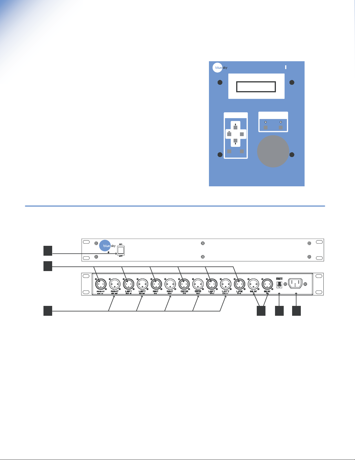
1. Power Switch - This switch controls the power to the
BMC | Remote and all internal electronics.
2. 5.1 Channel Inputs - These XLR inputs should be connected
to the 5.1 channel outputs of your console or digital
workstation. The inputs are electronically balanced. Do not
connect more than one source to these inputs. Refer to the
wiring table on page 10 for wiring custom cables and
connectors.
3. L, C, R, LS & RS Outputs - These XLR outputs should be
connected to the inputs of the active satellite speakers.
These outputs are electronically balanced. These outputs can
be full range or bass-managed with a bandwidth limited to
spectral content above 80Hz. Refer to the wiring table on
page 10 for wiring custom cables and connectors.
4. Parallel Subwoofer Outputs - These outputs can be used to
drive one or more subwoofers. The output signal is the sum
total of both the LFE and the bass-managed subwoofer signal
(when the bass-management feature is being used). Refer to
the wiring table on page 10 for wiring custom cables and
connectors.
5. Remote Control RJ-11 Connector - This standard six
conductor RJ-11 jack is used to connect the main I/O unit to
the BMC | Remote. The remote control cable length should
not exceed 100 Feet.
6. IEC Power Terminal - Input Power Voltage I20 VAC / 60Hz
or 240 VAC 50 / 60HZ (set at the factory), rated for 15-
Watts. Use the included IEC Power Cable.
bass management controller
Page 4
Page 5

bass management controller
3. A Tour of the BMC | Remote
1. RJ-11 Main BMC Control Output - Connect this plug to
the Main BMC I/O unit with the supplied 25 ft 6 conductor
phone cable. This cable can be extended to a maximum
of 100ft using standard 6 conductor phone (not data)
cable.
blue sky | BMC
Owner's Manual for 5.1 Applications Issue 1, rev 2
2. RJ-11 Aux BMC Control Output - Reserved for future
expansion.
3. + / YES Button - Used to adjust parameters within the
submenus. Press to increase individual channel levels,
mute channels and set the reference gain setting. See
the Software Overview section on page 6 for more
information.
4. Arrow Up - Navigation Button - Used to scroll up through
the software submenus. See the Software Overview
section on page 6 for more information.
5. - / NO Button - Used to adjust parameters within the
software. Press to decrease individual channel levels
and un-mute channels. See the Software Overview
section on page 6 for more information.
6. Arrow Down - Navigation Button - Used to scroll down
through the software submenus. See the Software
Overview section on page 6 for more information.
7. REF (reference) LED - "ON" when the system gain is set
to the user predefined reference level setting. See item
10 below.
8. MUTE LED - "On" when all outputs have been muted.
"Flashing" when one or more channels have been muted
within the "Mute Channels" submenu of the software. See
item 9 below.
Main Aux
1 2
bass management controller
3
BLUE SKY INT
REV 1.0
remote
7
4
8
MENU
5
+
NO
YES
6
SELECT CANCEL
GAIN
REF
MUTE
9
10
9. MUTE Control Button - Toggles the system in and out of
mute. Press this button to mute all outputs. Press again
to cancel Mute. Moving the Volume Control Knob will
also cancel mute . See the Software Overview section on
page 6 for more information
10. REF (reference) Control Button - Toggles the system in
and out of reference gain. Press this button to set the
gain to the user defined reference gain. Press again to
cancel. Moving the Volume Control Knob will bring the
system out of the reference setting. See the Software
Overview section on page 6 and the 5.1 System
Calibration Section on page 9 for more information
11. SELECT Button - Press to activate menu and press again
to scroll through the main software menus, "Mute
Channels", "Calibrate CH(annels)" and "Setup Menu".
See the Software Overview section on page 6 and the
5.1 System Calibration Section on page 9 for more
information.
11 12 13
12. CANCEL Button - Press to cycle backwards through the
menu and to cancel menu operation. See the Software
Overview section on page 6 for more information.
13. VOLUME Control Knob - Turn to control to set overall
nominal system gain from -50 dB to 0 dB, in .5dB
increments. Turning this knob will cancel MUTE and REF
gain operation . Turning this knob while in the menus will
temporarily override menu operation to adjust the system
gain. Once knob is released, the menu will be
reactivated.
Page 5
Page 6

blue sky | BMC
Owner's Manual for 5.1 Applications Issue 1, rev 2
4. System & Software Overview
System Gain
The BMC is a studio quality bass management controller with an integral
multi-channel volume control. The input stage is designed for a maximum
input level of +24dBu (balanced or unbalance) before clipping. The
output stage will also drive a balanced 10K Ohm load to a maximum of
+24dBu. However, because the BMC can add up to +6dB of gain to a
channel to balance the system, there are situations where the BMC will
clip. For example you cannot take a +24dBu input, set the system gain at
0dB , add +6dB of calibration gain to the signal and get +30dB on the
output. The output amplifiers in the BMC will clip under these conditions.
System Power Up Sequence -
1. Although the system will startup without the BMC | Remote
being connected, in order to calibrate the system and gain full
access to all of the systems features, the BMC | Remote must
be connected to the I/O box(es). Once the system has been
calibrated, the remote can be disconnected and the main I/O
unit will retain all the setup information. Once the systems'
power is cycled, the main I/O box will power up fully
calibrated and at the "reference" position. See the Software
Overview section on this page and the 5.1 System Calibration
Section on page 9 for more information.
2. The startup sequence is activated when ever a remote is
connected to the I/O box or when the power is cycled with
the remote connected. The power up sequence is as follows A: The LEDs may flash momentarily as the remote receives
power from the main I/O unit. The power LED on the front of
the I/O box(es) should be lit.
B: Within the I/O box(es) the output relays will click on.
C: The LCD will display the current software version for 5
seconds. "Blue Sky Ver REV 1.0"
D: After the system has been fully activated the system will go
into the mute mode and the display will show the following
message. "SYSTEM MUTED".
Although this may seem to be a limitation, in practice it is not. The Blue
Sky monitors, like most amplified monitors, have relatively high voltage
sensitivity. Therefore, there is quite a bit of flexibility in setting gains.
For the best signal to noise ratio and to minimize noise and hum pickup,
the BMC should be driven with as high a signal level as possible. The
output signal going to the speakers should be kept relatively high and if
necessary signals should be attenuated at the monitors.
BMC Power Up Sequence
P
U
R
E
W
O
P
S
E
Y
IS
E
T
O
M
E
R
?
D
E
T
C
E
N
N
O
C
O
N
D
A
O
L
E
T
A
T
S
T
S
A
L
IN
A
G
F
E
R
R
O
F
IT
A
W
S
N
IO
T
C
U
R
T
S
IN
R
F
E
T
O
M
E
R
M
O
Page 6
CANCEL
MENU
SELECT SELECT SELECT
MUTE
MENU
RSUR
NO / YES
LSUR
NO / YES
RIGHT
NO / YES
CENTER
NO / YES
LEFT
NO / YES
SUB
NO / YES
BMC Software Overview
CAL
MENU
RSUR
-6 / +6dB
LSUR
-6 / +6dB
RIGHT
-6 / +6dB
CENTER
-6 / +6dB
LEFT
-6 / +6dB
SUB
-6 / +6dB
LFE
0 or 10dB
UP / DOWN ARROW
UP / DOWN ARROW UP / DOWN ARROW
SETUP
MENU
BASS
MANAGER
ON
SET
REF
GAIN
YES
NO
80HZ HIGH
PASS
IN
120HZ LOW
PASS LFE
FILTER IN
BASS
SUM ON
ADJUST
GAIN
CONTROL
HIT
YES TO
STORE
80HZ HIGH
PASS
OUT
120HZ LOW
PASS LFE
FILTER OUT
BASS
SUM OFF
Page 7

blue sky | BMC
Owner's Manual for 5.1 Applications Issue 1, rev 2
5. 5.1 Speaker Placement
Satellite Speaker Placement - MUSIC
The recommended monitoring angle for proper stereo imaging with music
is 60 degrees between the left and right speakers. The center channel
speaker should be located on axis with the reference monitoring position
and both the left and right surround channel speakers should be at an
angle of 110 degrees from the centerline. In most applications, surrounds
used for music are placed at the same height as the front speakers for a
direct sound field. See Figure 1
Satellite Speaker Placement - FILM / POST PRODUCTION
Although the above recommendations should work equally well for both
film and music production, there may be situations where a more "film"
optimized setup is desirable. To correctly relate audio to picture, the
recommended angle between left and right speakers is 45 degrees.
This narrower monitoring angle should still yield a very satisfactory stereo
image. As with the "music" setup, the center channel speaker, should
still be located on axis with the reference monitoring position. Unlike
music surrounds, which tend to be direct in nature, film surrounds are
usually positioned for a more diffused sound field to simulate the effect of
an array of surround speakers used in a theater. For a single pair of
surrounds, this can be accomplished by placing them two feet above
seated ear height, to the side of the monitoring position and slightly by
behind the mix position. For larger rooms, it may also be desirable to use
multiple surround speakers as an "array".
Satellite Speaker Monitoring Height Recommendations
B
C
Figure 1
RL
D = B
LS
Reference Monitoring Position
30˚
110˚
RS
SPEAKER PLACEMENT AS DOCUMENTED IN
RECOMMENDATION ITU-R BS.775-1
It is recommended that all of the satellite speakers be placed at or about
seated ear height, as shown in Figure 2. If it is not possible to place the
speakers at or about seated ear height, please aim the speakers at the
monitoring position.
Subwoofer Speaker Placement
Although you have great flexibility in positioning a subwoofer, a good
starting point is centered between the left and right satellite speakers. This
could be under the console, behind the console, etc. Placing the
subwoofer closer to a corner or wall will increase acoustic efficiency and
may yield better acoustic response in many situations. However, because
of the many variables that relate to "in-room" subwoofer performance, we
highly recommend experimenting with subwoofer placement.
Speaker placement recommendations, with regard to these types of
installations, vary greatly on the end users' goals and surround
philosophy. For more specific information regarding your particular
installation, please do not hesitate to contact Blue Sky directly.
www.abluesky.com
Figure 2
Center of the tweeter
Center of the woofer
Mid-point of the woofer and tweeter
MONITORING HEIGHT
RECOMMENDATIONS
Page 7
Page 8

blue sky | BMC
Owner's Manual for 5.1 Applications Issue 1, rev 2
6. System Wiring Diagram
5.1 Channel Output From Console or Workstation
bass management controller
BMC Remote
Control Cable
5.1 Channel Output From
the BMC going to the monitoring
system. NOTE: Connect the
Subwoofer output to the
DIRECT input on the subwoofer.
SUB
C
RL
LS
RS
Page 8
5.1 Channel Monitoring System
Page 9

7. 5.1 System Calibration
The following system calibration instructions are for a bass-managed
speaker system, such as Blue Sky's ProDesk or Sky System One.
Step 1 "BASS MANAGER - ON"- Press SELECT three times, or until the
display reads "SETUP MENU". Press the UP or DOWN ARROW keys until
the display reads "BASS MANAGER - ON". If the display reads "BASS
MANAGER - OFF", press YES To turn it on. Now press CANCEL until
you have backed out of all the menus.
85
80
LFE Channel +10dB
75
above Main Channel
Ref
70
Bass-Managed
Subwoofer
Channel = 79dBC
65
60
blue sky | BMC
Owner's Manual for 5.1 Applications Issue 1, rev 2
5.1 Channel Calibrated System Response
80 dB Ref Line for LFE = Approximately 89dBC
70dB Ref Line = Approximately 85dBC for each main & surround
channel
STEP 2 "MUTE THE SUBWOOFER" - Press the SELECT once, or until the
display reads "MUTE CHANNELS". Press the UP or DOWN ARROW until
you get to the subwoofer channel and then press YES . The MUTE LED
will flash. Now press CANCEL until you have backed out of all the
menus.
STEP 3 "FINDING YOUR REFERENCE LEVEL" - Turn the gain on the remote
to -50dB. Patch a pink noise generator, tape or other source with at least
60 seconds of 0dBVU Pink Noise into your console or workstation. If you
are using a digital source, the test signal should measure -20dB FS (0dB FS
= Full Scale Digital). Assign the test signal to the center channel only.
Confirm that all your speakers are turned on and that the gain on each
speaker is set to a moderate level. Slowly bring up the gain with the
master Volume Control knob on the BMC | Remote until you measure
85dB on the C scale, with the response set to Slow. Measure SPL exactly
at the reference mix position, with the SPL meter at arms length, the
microphone at seated ear height, angled at approximately 45 degrees,
and pointed at the center speaker. If you are using a 1/3 octave RTA, align
the level of the speakers to 70dB reference line on the analyzer. Note the
gain displayed on the remote when the center channel is at 85dBc. If it is
less than -20dB turn the gain on the back of the center channel monitor
down and increase the level of the BMC until a good compromise is
reached. Typically using a reference gain setting of -10dB is a good
choice between overall electrical headroom, input signal level, output
signal level and giving you an additional 10dB of system gain when
necessary.
Once the "Reference Level" setting has been determined, turn off the pink
noise, make a note of the System gain reading on the remote. Set the gain
controls of the rest of the monitors to the same level as the center channel.
Now follow STEP 4 to enter the "Reference Level" into memory.
55
50
45
z
H
5
2
1
3
z
z
z
z
z
H
H
0
.5
4
5
z
z
H
H
3
0
6
8
z
H
H
H
H
0
0
5
0
0
2
6
1
1
1
2
BASS-MANAGED SUBWOOFER (without LFE)
LS =
85dBC
Test Signal = 0dBu Pink Noise / -20dB FS (Full Scale Digital)
Measurement System = SPL Meter set to C Weighted & Slow
Reference Monitoring Position
5.1 Channel Monitoring System
Test Signal = 0dBu Pink Noise / -20dB FS (Full Scale Digital)
Measurement System = 1/3 Octave Real Time Analyzer
z
z
z
z
z
z
z
z
z
H
H
H
H
5
0
1
0
50
00
5
3
4
2
H
H
H
H
k
kH
0
0
5
1
0
3
00
8
6
.2
1
1
= 79dBC
C =
L =
85dBC
85dBC
k
.6
z
H
85dBC
2
R =
z
H
k
.5
2
z
z
z
z
H
H
kH
k
kH
k
5
4
5
.3k
.1
6
3
RS =
85dBC
z
z
z
z
z
z
h
H
H
H
K
8
1
H
kH
k
k
k
6
0
0
.5
1
2
2
1
STEP 4 "SETTING THE REFERENCE LEVEL" - Press SELECT three times,
or until the display reads "SETUP MENU". Press UP or DOWN ARROW
until "SET REF GAIN" is on the display. Turn the Volume Control
Knob until the SYSTEM GAIN equals the gain noted above in STEP 3.
Release the knob and press YES when the menu reappears. You have
now successfully stored the preset reference level. Press CANCEL three
times to exit the menu.
STEP 5 "FINAL SATELLITE SPEAKER CALIBRATION" (subwoofer should
still be muted) It is extremely important that you set the volume control
to the reference level prior to starting the calibration of the system. Do
not adjust the knob during the calibration function.
Press SELECT twice until the display reads "CALIBRATE CH". Press the
DOWN ARROW key until it reads RSUR (right surround). Turn on the
calibrated pink noise source (making sure to assign it to the channel that is
being calibrated) and trim the gain using the + or - keys until the SPL meter
reads 85dBc (for the surrounds it may be necessary to point the SPL meter
towards the back of the room to get a more accurate SPL measurement).
If you are using a 1/3 octave RTA, align the level of the speakers to the
70dB reference line on the analyzer. Once each channel is set, use the
DOWN ARROW key to scroll through the other channels and then use
the + or - buttons to adjust the level as described above. Stop when you
get to the SUB (subwoofer) and press CANCEL to exit this part of the
calibration.
STEP 6 "SUBWOOFER CALIBRATION" Press SELECT once, or until the
display reads "MUTE CHANNELS". Mute the the Left, Center, Right, Left
Surround and Right Surround Channel by selecting, with the DOWN
ARROW key, and pressing YES . Un-mute the Subwoofer Channel (by
pressing the NO button). The Mute LED will flash.
Confirm that the volume control is set at the "Reference Level" as
described in STEP 3. Press SELECT Two times, or until the display reads
"CALIBRATE CH". Press the DOWN ARROW key to scroll through each
channel until you get to the SUB (subwoofer). Feed the pink noise to the
CENTER channel only. No noise should be coming from any of the satellite
speakers (they are muted). Now, using your SPL meter, adjust the level of
the subwoofer until it reads 79dBc (allow enough time for the display to
settle and make a mental average), you may also need to physically adjust
the gain on the subwoofer. If you are using a 1/3 octave RTA, align the
level of the subwoofer to the 70dB reference line on the analyzer. Next,
turn off the pink noise signal, press the DOWN ARROW button, and
press YES to set the LFE to +10dB (as recommended by Dolby). Press
CANCEL to go back to the MUTE MENU and un-mute each channel (the
mute LED should be off when this step is completed). The calibration
process is now complete! Please make a note of all the settings.
(Additional Setup information is available on page 10.)
Page 9
Page 10

XLR
)
)
3
g
)
()()()()
()()()()
()()
()
()
ppp
p
p
p
p
p
p
gggg
PUSH
RIGHT
IN
RIGHT
OUT
blue sky | BMC
Owner's Manual for 5.1 Applications Issue 1, rev 2
8. Additional Setup Information
Using the Blue Sky | BMC as a multi-channel volume control
There may be applications where the Blue Sky | BMC may only be used as
a multi-channel volume control. The bass-manager OFF function can be
accessed within the SETUP MENU. Once at this menu, press the down
arrow button until the display reads Bass-Manager. Press the NO button to
defeat the bass-management function. Once this is done, the unit will
operate purely as a six channel volume control (press cancel to escape
out of this menu). The LFE 120Hz low pass-filer will now also be
defeated (making the LFE input/output full-range). However, the LFE +10 /
0dB boost can still be selected. To defeat this, enter the Calibrate CH.
menu, scroll down using the arrow down buttons, and toggle the setting
using the + / - buttons. Once the desired setting has been entered, press
cancel to exit this menu.
The LFE Channel
The LFE Channel was originally designed for film applications as a way to
extend the low frequency "head-room" (not frequency response) of the
playback system. This additional headroom was created by adding
+10dB of in-band gain to the LFE channel. This channel should only be
used when no additional headroom is available in the other channels for
low frequency effects. As an example, you may use the LFE channel to
increase the dynamic low frequency content of a movie that has many
large explosions. This is rarely the case in music, although there may be
some creative reasons to use the LFE from time to time. It is important to
note that no "significant" audio should be sent exclusively to the LFE
channel. The reason for this is that if a Dolby Digital audio track is folded
down to 2-channels, which can happen if a consumer doesn't have a
surround system, the LFE channel will not be added to the fold-down mix
(all other channels will be added to the fold-down).
Future Expansion
The Blue Sky | BMC is a digitally controlled analog product. It was
designed to be software upgradeable. Please check the Blue Sky website
for future upgrades. www.abluesky.com
Need to know more about
multi-channel audio?
There is a wide variety of technical
information available on the internet regarding
multi-channel audio. If you need more
specific information regarding multi-channel
audio and Blue Sky International, please do
not hesitate to contact us directly.
www.abluesky.com
Additional Technical Resources -
Source: The Audio Engineering Society
Website: www.aes.org
Source: Digital Theater Systems, Inc.
Website: www.dtsonline.com
Source: Dolby Laboratories
Website: www.dolby.com
Source: Society of Motion Picture and
Television Engineers
Website: www.smpte.org
Source: Surround Associates
Website: www.surroundassociates.com
Source: The THX Division of Lucasfilm Ltd.
Website: www.thx.com
9. Cable and Wiring Information
Page 10
Use high-quality, shielded cables to connect your console, workstation or
other source to your Blue Sky | BMC. Foil-shielded cables, such as Belden
8451, 8761, or 9501 should do quite well. Other high quality cables are
available and those that incorporate better shielding will yield an overall
higher noise rejection, lowering your systems susceptibility to external
interference. Another important tip to keep in mind when wiring your
system is to route all line level cables away from the AC and other power
sources, this will reduce the probability of having AC hum emanating from
your monitoring system..
TRS RCA
T (+
LD (-
SHIELD (Ground
Pin
n 2
in
Shield Shield
RIGHT
IN
PUSH
RIGHT
OUT
Page 11

10. Technical Information
Input Impedance 20k Ohms balanced
Common Mode Rejection Ratio 40dB typical @60Hz
Maximum Input Level (all inputs) +24dBu balanced
Maximum Output Level +24dBu balanced
Output Impedance 200 Ohms balanced
Nominal max gain 0 dB
Gain trim range +/- 6dB
Signal to noise ratio > 105dB
Output noise -85dBu (20 to 20kHz)
THD + Noise (0dB of gain) .002% @ 1kHz @ +10dBu
Frequency Response 20 Hz to 20KHz +/- .25dB
(Volume Control Mode)
High-Pass Filter type 2nd order Linkwitz-Riley
High-Pass Filter Cutoff 80Hz
Low-Pass Filter Type 4th order Linkwitz-
Riley
Low-Pass Cutoff 80Hz
LFE Input
Gain 0dB / +10dB Selectable
Low-Pass Filter 120Hz
CHANNEL
IN
REMOTE
CONTROL
LFE
IN
other channels
input
blue sky | BMC
Owner's Manual for 5.1 Applications Issue 1, rev 2
BMC BLOCK DIAGRAM
1 of 5 input channels
DIGITALLY
12 dB / OCT
MICRO
CONTROLLER
1 / 10x
gain
CONTROL
ANALOG
80 HZ
HIGH PASS
POT
BYPASS
24 dB / OCT
80 HZ
LOW PASS
BASS SUM
24 dB / OCT
120 HZ
LOW PASS
INPUT
SELECT
outputinput
DIGITALLY
CONTROL
ANALOG
POT
CHANNEL
OUT
output
LFE
OUT
Input power 120 VAC 60HZ
240 VAC 50/60HZ
15-Watts
(Voltage set at the factory)
11. Product Dimensions
5.0"
6.20"
8.00"
1.75"
17.35"
6.01"
bass management controller
1.4"
19.00"
2.6"
Page 11
Page 12

blue sky | BMC
Owner's Manual for 5.1 Applications Issue 1, rev 2
12. Factory Service Instructions
Service for the U.S. versions of Blue Sky products is available only
from our authorized distributor, Group One Ltd., located in
Farmingdale, New York. (Service for Blue Sky products outside the
United States can be obtained through local dealers or distributors.)
If your Blue Sky | BMC needs service, follow these instructions:
1. Review the manual and ensure that you have followed all
setup and operating instructions.
2. Call (631) 249-1399 9:00am to 5:30pm EST and ask for
Customer Service. Explain the problem and request an RA
(Return Authorization) number. It is important to have your
product serial number available when you call. You must have
an RA number before you can obtain service.
3. Pack the product in its original packing material and box
(do not return the power cord or the manual). If you don’t
have the original packing material and/or box, please let
Customer Service know when you call for the RA number.
Blue Sky is not responsible for any damage that occurs
due to non-factory packaging.
4. Include a legible note stating your name, shipping address (no
P.O. boxes), daytime phone number, RA number, and a
detailed
description of the problem, including how it can be
duplicated.
5. Write the RA number on the top of the carton.
Blue Sky International
ATTN: SERVICE DEPT / RA#
70 Sea Lane
Farmingdale, NY 11735
USA
7. Turnaround time is three to fi ve business days depending on
the problem. When calling for RA numbers, please ask
Customer Service what the turnaround time is. The serviced
product will be sent back to you via the same shipping
method as received (i.e. if you ship your monitor UPS Ground
it will be returned UPS Ground, UPS Red will be returned UPS
Red etc...). This only applies to products serviced under the
warranty.
6. Ship the product to the address below. We recommend
United Parcel Service (UPS). Please insure the product
regardless of shipping method.
13. Contact Details
For sales and other enquiries, please contact Blue Sky at:
Blue Sky International
70 Sea Lane
Farmingdale, NY 11735
USA
tel: 516 249 3662
fax: 516 249 8870
email info@abluesky.com
To discover the very latest information check out our website at:
www.abluesky.com
Page 12
Copyright © 2002~2003 Blue Sky International
 Loading...