

Page 1
Marine Electrical Prod
206.4mm
ucts
SMS Surface Mount System
PN 3113 / PN 3116 / PN 3117 / PN 3118 / PN 3119 / PN 3120
Meets ABYC E11 when used with an ELCI Main circuit breaker and
mounted within 10 feet of the shore power inlet
WARNING
The Surface Mount System panel enclosure should be installed by a
certied marine electrician.
DANGER
Hazardous voltage. Improper handling can cause death or serious injury.
Turn off any shore sources and disconnect shore cord(s). Lock out other
AC power sources before beginning electrical installation.
• Models available with ELCI Main circuit breakers for 120V 30A, 120V 50A,
and 120/240V 50A
• Blank apertures for custom breaker loading
• Glass lled polycarbonate base
• Clear cover allows easy view of circuit breaker status
• Overlapping cover for strength and increased gasket protection
• Oversized, formed in place seamless PUR gasket
• Easily removable stainless steel hinge pin for unobstructed installation
• Stainless steel latch secures cover without penetrating the enclosure
• Blank circuit positions accommodate Carling Technologies™
A and C Series Flat or Raised Rocker and ELCI Main circuit breakers
• Stainless steel mounting hardware included
• Includes waterproof glands (3116, 3117, 3118, 3119, 3120)
• LED lights for back lighting and ON indication (3116, 3117, 3118, 3119, 3120)
GUARANTEE: Blue Sea Systems stands behind its products for as long
as you own them. Find detailed information at www.bluesea.com/about.
For customer service, call 800-222-7617.
Blue Sea Systems Inc. p 360.738.8230
425 Sequoia Drive f 360.734.4195
Bellingham, WA 98226 USA conductor@bluesea.com
www.bluesea.com
980009910 Rev.004
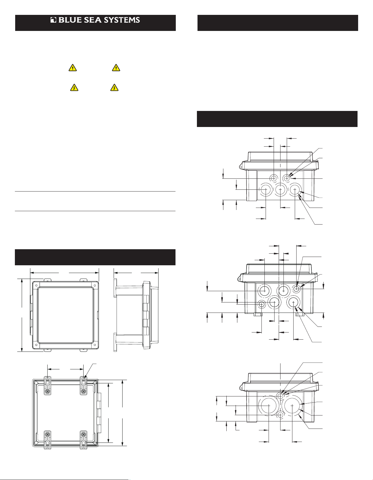
Enclosure Dimensions
7.65"
194.2mm
4.96"
126.1mm
Specications
Box Specications
Temperature Range −40°C to +85°C
Cover Screws and Hardware 10-32, stainless steel
Mounting Hardware ¼" diameter, #12, (6 mm)
Regulatory
IP66—Protected against powerful water jets
Flammability rating—Per UL 508
Toxicity— Non-toxic, halogen free, RoHS compliant
UL Listed and NEMA 4X rated, NEMA Type 4, 4X, 6, 6P, 12, and 13
Specications subject to change. See www.bluesea.com for additional information and specications
Drill Guides
1.25"
31.8mm
PG 7
CABLE
GLAND
Ø.49" THRU
12.5mm
Ø.80"
20.3mm
CLEARANCE
FOR LOCK NUT
PG 16
CABLE
GLAND
Ø.89" THRU
22.5mm
Ø1.30"
33mm
CLEARANCE
FOR LOCK NUT
2X Ø.49"
12.5mm THRU
FOR PG 7
CABLE GLAND
Ø.80"
20.3mm
CLEARANCE
FOR LOCK NUT
2X 2.08"
52.7mm
3X 1.00"
25.4mm
.63"
15.9mm
1.40"
35.6mm
2.80"
71.1mm
PN 3116
42mm
1.38"
35mm
1.65"
11mm
.43"
8.13"
4.00"
101.6mm
CLEARANCE FOR:
1/4", #12, OR 6mm
Ø
MOUNTING HARDWARE
6.65"
168.8mm
186.8mm
7.35"
2X 2.08"
52.7mm
2X 1.00"
25.4mm
2.40"
61mm
2X
1.50"
38.1mm
.80"
20.4mm
15.2mm
.60"
.43"
11mm
1.65"
42mm
1.38"
35mm
PN 3117
1.13"
28.6mm
2.25"
57.2mm
PN 3118, 3119, 3120
2.27"
57.7mm
Ø1.30"
33mm
CLEARANCE
FOR LOCK NUT
2X Ø.89"
22.5mm THRU
FOR PG 16
CABLE GLAND
PG 7
CABLE
GLAND
Ø.49" THRU
12.5mm
Ø.80"
20.3mm
CLEARANCE
FOR LOCK NUT
PG 29
CABLE
GLAND
Ø1.47" THRU
37.3mm
Ø2.00"
50.8mm
CLEARANCE
FOR LOCK NUT
Page 2
SEALING NUT
SUGGESTED CLEARANCE HOL
FOR NONTHREADED MOUNTING
Installation
Components Included
Required Tools
• Hole Saw, drill or step drill suitable for cable glands (see information on back).
• Drill motor suitable for above
• Screw Drivers
• Knife
• Measuring device
• Wire cutters and Crimpers
Required Parts
• Suitable ring terminals for circuit breaker and grounding connections
• In some installations it may be desirable to attach a mounting substrate to the
hull with adhesive or epoxy instead of screwing directly to the hull.
Installing the Enclosure Panel
• The Surface Mount System Enclosure Panel should be installed by a certied
marine electrician.
• Plan the installation by determining where the enclosure will be mounted
o Per ABYC, the enclosure cannot be mounted further than the reach of a 10'
cable from the AC power inlet
o Consider the needed clearances to access the enclosure and open the sealed cover
o Allow for a wire drip loop outside the enclosure and sufcient service loop
for wires inside the enclosure
• Determine which included glands are needed. It is recommended that glands be
installed on the bottom of the enclosure to maintain the waterproof integrity of
the sealed enclosure.
• Smaller glands may permit convenient installation of a galvanic isolator if used
in the systems. In this case the line safety ground wire would exit the enclosure
to the galvanic isolator and the boat side of the galvanic isolator would return to
the enclosure to join the internal connections and the ground from the load side
power cable.
• Try all cable glands on the wire for correct t before proceeding.
• Flat cables can be manipulated to a nearly round shape to t and seal better
in the gland.
• Large round cables with #6 Wire may be a very tight t in the cable gland.
Dismantle the gland and use wire lubricant to ease cable through the rubber
seal if necessary.
• When drilling holes for cable glands, be sure to allow sufcient clearance inside
for the nut. The best location is as close to the back of the enclosure as
possible and still allow for the nut.
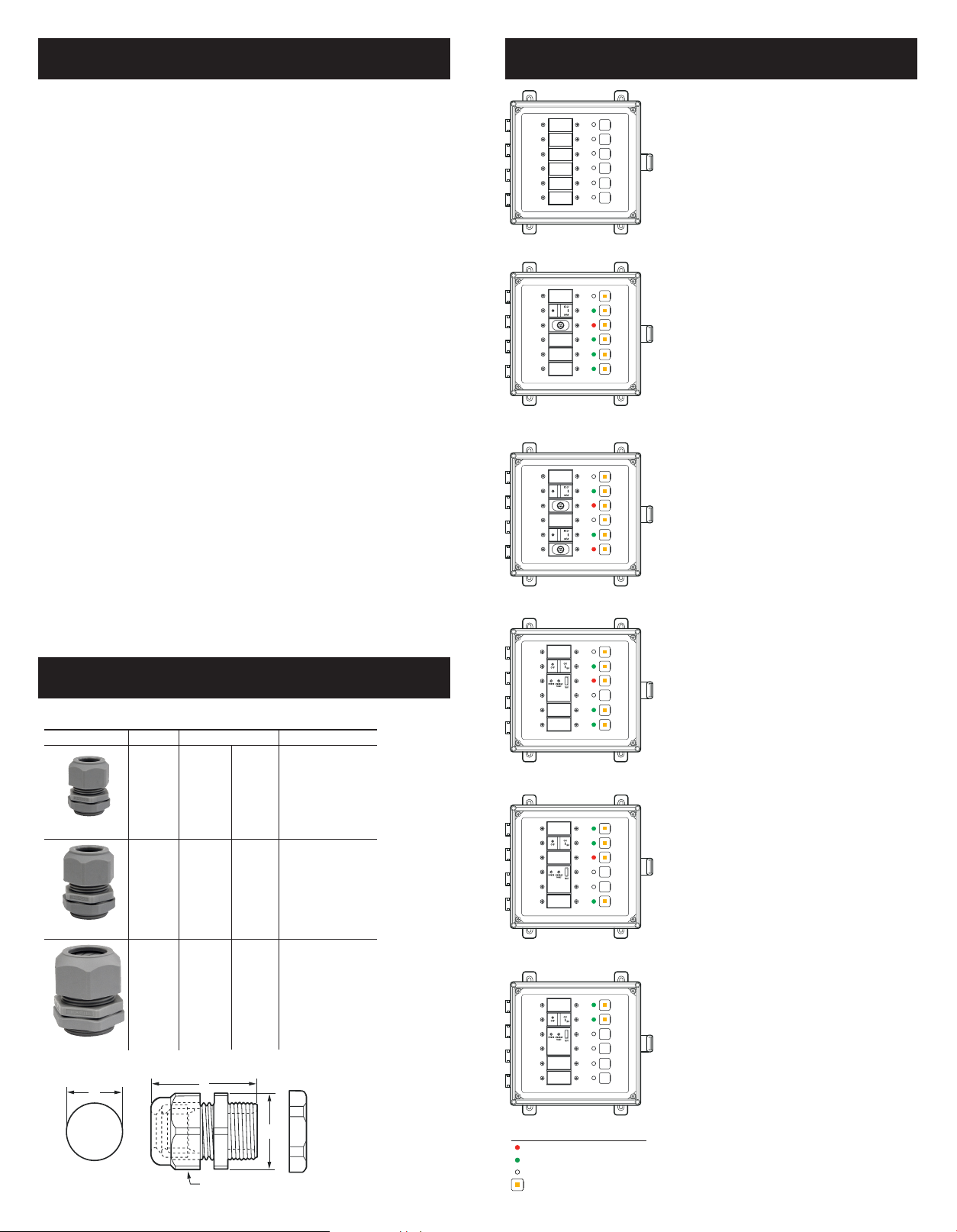
3113 SMS Panel Enclosure Includes:
6 blank circuit positions
6 LED plugs
12 circuit breaker mounting screws
30 Basic DC labels, 4205
30 Basic AC labels, 4206
Panel Voltage ID labels
12V DC, 24V DC
120V AC, 230V AC,
120/240V AC
3116 SMS Panel Enclosure Includes:
ELCI Main + 3 blank circuit positions
1 ELCI Main 120V 30A, 30mA, 3102
2 small wire glands, 3124
3 medium wire glands, 3125
4 green “ON” indicating 120V AC LEDs, 8034
1 red “Reverse Polarity” indicating 120V AC LED, 8066
1 LED plug
12 circuit breaker mounting screws
6 Backlit circuit label positions
1 AC Main label, 1 Reverse Polarity label, 1 ELCI label
30 Basic AC labels, 4206
Panel Voltage ID label-120V AC
3117 SMS Panel Enclosure Includes:
2 x 120V AC / 30A ELCI Main
2 ELCI Main 120V 30A, 30mA, 3102
2 small wire glands, 3124
4 medium wire glands, 3125
2 green “ON” indicating 120V AC LEDs, 8034
2 red “Reverse Polarity” indicating 120V AC LEDs, 8066
2 LED plugs
12 circuit breaker mounting screws
6 Backlit circuit label positions
Source Selection Label Set (10 labels)
2 Reverse Polarity labels, 2 ELCI labels
Panel Voltage ID label-120V AC
Gland Specications
Gland Specifications
Small 3124 (PG7)
Medium 3125 (PG16)
Large 3126 (PG29)
A
WIRE SIZE
#14 to
#10
Single
Wire
#14 to
#10
Cable,
3 Conductor
#6
Cable,
4 Conductor
CABLE DIA. RANGE DIMENSIONS
Min. Dia. Max. Dia.
.114 in
2.9 mm
.230 in
5.8 mm
.590 in
15.0 mm
.250 in
6.4 mm
.530 in
13.9 mm
.990 in
25.4 mm
B
A. Clearance Hole
.492 in (12.5 mm)
B. Max. O. A. Length
1.17 in (29.7 mm)
C. Wrenching Flats
.59 in (15.0 mm)
Reference diagram below
A. Clearance Hole
.886 in (22.5 mm)
B. Max. O. A. Length
1.66 in (42.2 mm)
C. Wrenching Flats
1.05 in (26.7 mm)
Reference diagram below
A. Clearance Hole
1.470 in (37.3 mm)
B. Max. O. A. Length
2.23 in (56.6 mm)
C. Wrenching Flats
1.66 in (42.2 mm)
Reference diagram below
3118 SMS Panel Enclosure Includes:
ELCI Main + 2 blank circuit positions
1 ELCI Main 120V 50A, 30mA, 3103
2 small wire glands, 3124
1 medium wire gland, 3125
2 large wire glands, 3126
3 green “ON” indicating 120V AC LEDs, 8034
1 red “Reverse Polarity” indicating 120V AC LED, 8066
2 LED plugs
12 circuit breaker mounting screws
5 Backlit circuit label positions
1 AC Main label, 1 Reverse Polarity label, 1 ELCI label
30 Basic AC labels, 4206
Panel Voltage ID label-120V AC
3119 SMS Panel Enclosure Includes:
ELCI Main + 1 blank circuit position
1 ELCI Main 120/240V, 50A, 30mA, 3104
2 small wire glands, 3124
1 medium wire gland, 3125
2 large wire glands, 3126
3 green “ON” indicating 120V AC LEDs, 8034
1 red “Reverse Polarity” indicating 120V AC LED, 8066
3 LED plugs
12 circuit breaker mounting screws
4 Backlit circuit label positions
1 AC Main label, 1 Reverse Polarity label, 1 ELCI label
30 Basic AC labels, 4206
Panel Voltage ID label-120V/240V AC
3120 SMS Panel Enclosure Includes:
ELCI Main for Isolation Transformer
1 ELCI Main 240V, 50A, 30mA, 3093
2 small wire glands, 3124
1 medium wire gland, 3125
2 large wire glands, 3126
2 green “ON” indicating 240V AC LEDs, 6806
4 LED plugs
12 circuit breaker mounting screws
2 backlit circuit label positions
1 AC Main label, 1 ELCI label,
Panel Voltage ID Label- 240V AC
E
C
KEY
Red circuit status indicator LED
Green circuit status indicator LED
LED plug
Backlit circuit label position
 Loading...