


P12
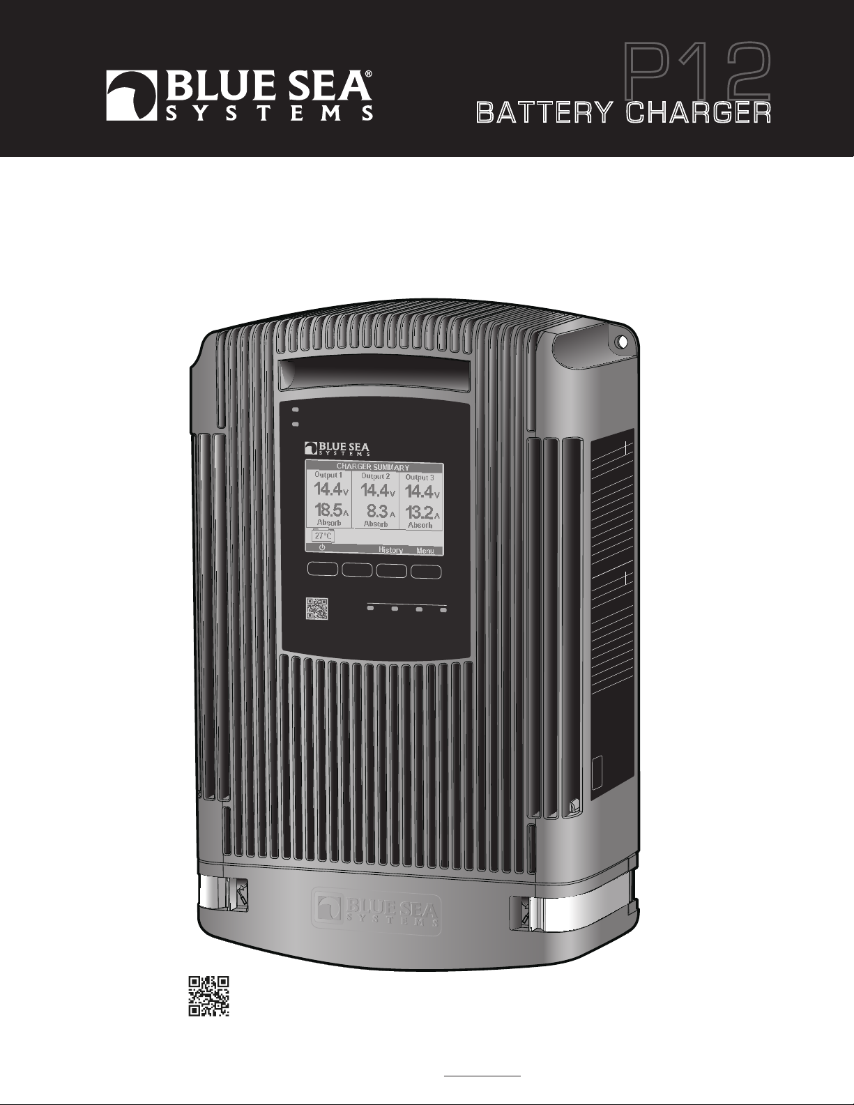
BATTERY CHARGER
User Manual
7521 (25A) and 7522 (40A)
P12
CHA RGING
ALE RT
Quick Guide
Pate nt Pe nding
12V DC
P12
BAT TERY CHARG ER
CH A RG IN G S TA G E
EQUA LIZE – A LL LI GHTS FLASH
www. blues ea.co m
Part Number 7521 7522
Total Output Current (Limited) 25A 40A
Nominal Output Voltage 12V DC
Output Connections 3 positive
1 negative
Universal AC Input Voltage 90–265V AC
Nominal AC Input Frequency 45–65 Hz
Maximum Output Voltage 16.0V DC
Output Voltage Accuracy 0.05V DC
Minimum Operating Temperature -20°C (-4°F)
Maximum Operating Temperature 70°C (158°F)
Minimum Storage Temperature -30°C (-22°F)
Maximum Storage Temperature 80°C (176°F)
Maximum Parasitic Current 2mA
N° article 7521 7522
Courant maximum de sortie totale 25A 40A
Tension de sortie nominale 12V CC
FLOA TABSO RBBULK PREF LOAT
Raccordements de sortie 3 positifs
1 négatif
Tension d'entrée CA universelle 90–265V CA
Fréquence d'entrée CA nominale 45–65 Hz
Tension de sortie maxi. 16,0V CC
Précision de tension de sortie 0.05V CC
Température de fonctionnement mini. -20°C (-4°F)
Température de fonctionnement maxi. 70°C (158°F)
Température de stockage mini. -30°C (-22°F)
Température de stockage maxi. 80°C (176°F)
Courant parasite maxi. 2mA
Regulatory
Design and construction compliance to UL-1236
marine (including ignition protection) and CSA 22.2
No. 107.2-0 standards. Meets all elements of the
ABYC A-31 and certain NMEA requirements. To view
the most current regulatory certifications,
visit www.bluesea.com/P12.
DES IG NED
ASSEMBLED
and TESTED
in the
U SA
Scan for
additional
product
information
Read and understand the contents of this User Manual. It contains important safety, handling, and operational instructions for the P12 Battery Chargers.
This User Manual describes the product mentioned herein at the time of its publication. Specifications and performance are subject to change at the discretion
of Blue Sea Systems. To view the most current revision of this publication visit bluesea.com/P12.


Table of Contents
Important Safety Instructions 2
P12 Battery Charger Overview 3–4
Specifications 5
Installation Tables 5
• Table A: Minimum Recommended Wire Size
• Table B: Recommended DC Circuit Protection
• Table C: Typical AC Regional Wire Colors
• Table D: AC Wire - Circuit Protection Selection Chart
• Table E: Default Voltages by Battery Type
Product Dimensions and Installation Clearances 6
Included Components 7
Supplies Needed 8
Installation Instructions 9–10
Initial Charger Setup 11
Advanced Charger Setup 12–13
Reset to Manufacturer Defaults 13
Absorption Parameters and Timers 14
Temperature Parameters 15
Equalization 16–17
Screen Summary 18–19
Alert Screens and Diagnostics 20–21
Optional Installation 22–23
• Automatic Charging Relays (ACRs)
Optional P12 Battery Charger Remote 24–27
Warranty and Contact Information 28
P12 Charge Management System 29
Specifications are subject to change. See bluesea.com/P12 for current information.
1
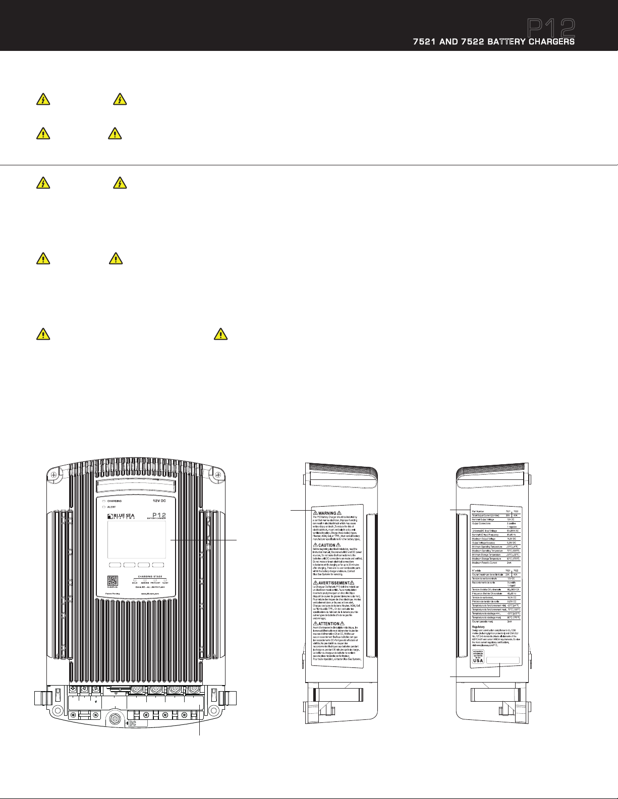
IMPORTANT SAFETY INSTRUCTIONS
7521 AND 7522 BATTERY CHARGERS
P12
READ AND SAVE THESE INSTRUCTIONS
WARNING
Refers to a potentially hazardous situation which, if not avoided, could result in death or serious injury.
CAUTION
Refers to a potentially hazardous situation which, if not avoided, may result in injury.
WARNING
The P12 Battery Charger should be installed by a qualified marine electrician. Improper installation can result in electrical shock which may
cause serious injury or death. To reduce the risk of electrical shock, mount vertically in a dry, well ventilated location. Charge these battery
types: Flooded, AGM, Gel, or TPPL Lead Acid batteries. Must consult battery manufacturer specifications for other battery types to
avoid damage.
CAUTION
Before beginning electrical installation, read the instruction manual. Disconnect all AC and DC power sources. Do not make final connections
to the batteries until DC connections on the charger are made and verified. Do not make or break electrical connections to batteries while
charging or for up to 30 minutes after charging. Other than parts accessed under the termination cover, there are no user serviceable parts
within the battery charger enclosure. Contact Blue Sea Systems for servicing.
GROUNDING PRECAUTIONS
Marine battery chargers and inverters have two grounding connections, one from the AC system and one from the DC system. ABYC requires
the AC grounding system to be connected to the DC grounding system through the distribution systems. Additionally, the chargers make
connections to both systems. It is very important the systems be connected properly before the charger is installed. Otherwise the charger
grounding system may become the sole connection between AC and DC ground and it may not be sized large enough to provide system wide
safety function. The AC grounding conductor is the conductor with green, or green with yellow stripe included in the AC power cable and should
be sized the same as the power and neutral conductors (see Table C page 5 for AC wire color). This will connect to the right most terminal in
the AC connection block. There is also chassis connection terminal for a DC safety grounding wire. The DC safety ground should be green or
marked green and sized equal to, or one wire size smaller, than the DC charge wires.
Warnings
Display
Specifications
Serial
Serial No. xxxxxxxxxxx
Number
M4 x 10
Line Neutral
Ground
AGC® 10A AC Fuse
− NEG
+ POS
+ POS
Battery Bus
DC Safety Ground
AC Input
Max.Torque 20 in-lb (2.25 Nm)
M3 x 25mm M3 x 30mm
SAFETY
GROUND
Battery 1
DC Output
Max.Torque 75 in-lb (8.47 Nm)
Battery 2
Battery 3
+ POS
Terminations
2
Specifications are subject to change. See bluesea.com/P12 for current information.

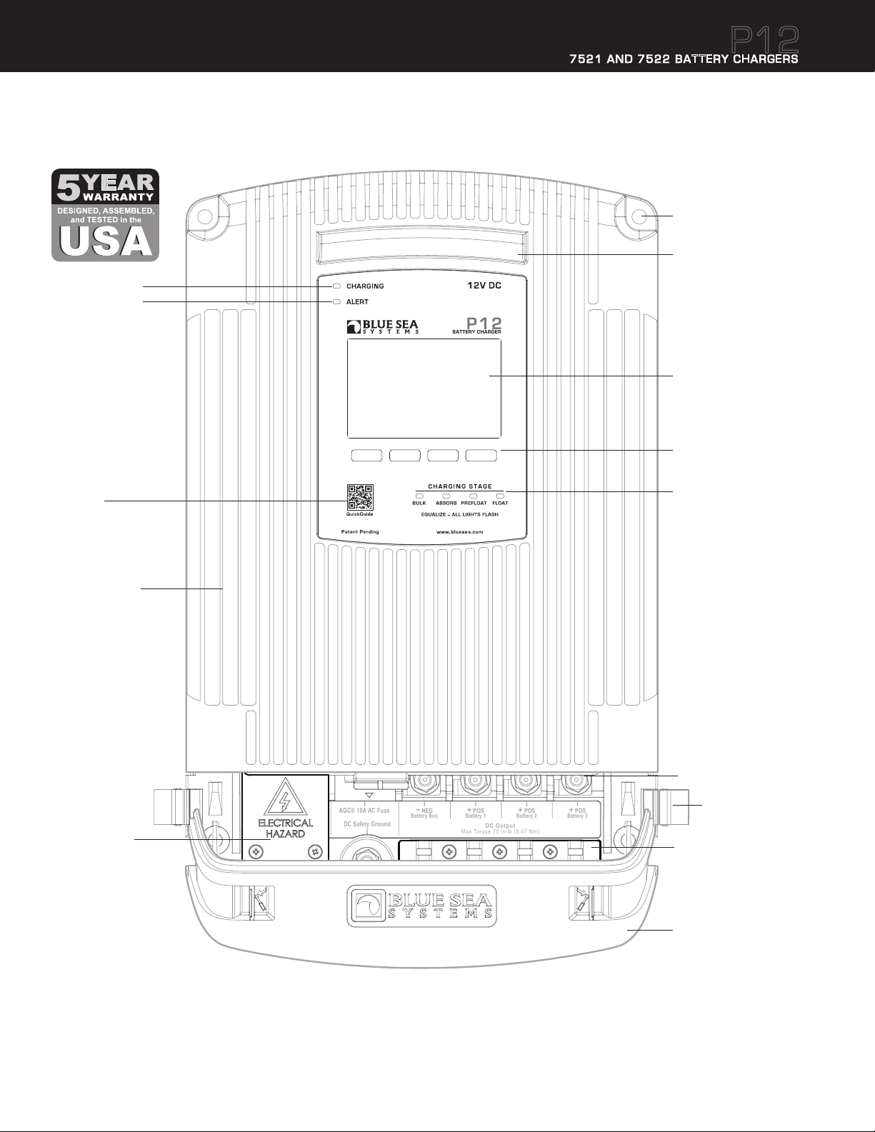
P12 Battery Charger Overview
7521 AND 7522 BATTERY CHARGERS
P12
The Blue Sea Systems P12 Battery Charger is dry mount device designed for use in marine applications and other harsh environments where reliability, ease of
use, and high performance are of primary importance. To this end, the P12 is designed, assembled, and tested in Bellingham, Washington, USA. Critical
components, including all electronic circuitry, are of US manufacture.
The P12 is designed to charge three electrically independent batteries or battery banks. The P12 has the unique capability to individually move each battery
out of the Absorption charging stage. This ensures batteries near their full charge do not continue to receive high constant voltages necessary in the Absorption
stage. This is optimal treatment for long battery life. Charge Coordination integrates with the Blue Sea Systems family of Automatic Charging Relays (ACR) to
force separation of the battery banks while the P12 is operational, to allow the batteries to individually exit the absorption stage. After fourteen days of
continuous Float, the charger will repeat the normal charge cycle to assure good battery health.
For reliability, the P12 has a rugged cast aluminum housing with high heat dissipating capability for minimum cooling fan run times. The electronic design has
given special consideration to operation in areas of inconsistent AC power quality. The P12 has a Power Factor Corrected nominal AC input range of 90V to
265V AC within which it will produce its full rated DC charging output. It will continue to produce reduced DC output to as low as 75V AC. After a shut down
below 75V AC or when there is interrupted switching between AC sources, like switching between generator and shore power, the P12 will automatically perform
an orderly restart.
Central to the P12’s ease of use is the large plain-language full graphics control screen capable of displaying in French, English, Italian, German and Spanish.
The plain language display enables clear communication with the operator for setting precise charging parameters and providing a broad range of easily understood fault communications and operating history. An optional remote display brings much of this functionality to a secondary location away from the charger.
The P12 contains charge profiles for most batteries available today, including Flooded Lead Acid (FLA), Gel, Thin Plate Pure Lead (TPPL), and Absorbed Glass
Mat (AGM). In addition, a user configurable charge profile is available for other battery types.
The P12 has built-in safety features including: ignition protection, over and under temperature protection (sensed internally and at the batteries), DC reverse
polarity protection, DC over voltage protection, and surge and shor t circuit protection.
Four Stage Battery Charging
The definitions of the P12 charging stages are defined below. The charging stage LEDs on the front of the charger will indicate the current stage.
Bulk (Constant current)
The Bulk charging stage is the first stage in the battery charging process. It is where a majority of the charging actually takes place leaving batteries at approximately
75% to 80% of their final capacity. The goal of the Bulk stage is to drive current into the batteries quickly to increase their voltage. Once all the batteries have reached the
defined Absorption voltage then the charger will move them into the Absorption stage.
Absorption (Constant voltage)
In the Absorption charging stage the batteries complete their charging by being “topped off”. This is a less aggressive charging stage than bulk where the current going into a
particular battery bank will significantly reduce with time. The conditions for a battery bank to be considered “full” vary based on many different factors. In order for a battery
bank to leave the Absorption stage a number of different parameters must be met. The main parameters are the Absorption Timers which can be seen on
page 14. Outputs move individually from Absorption to Pre-Float. When all batteries have completed Absorption, the charger will move them into the Float stage.
Pre-Float (Constant voltage)
The Pre-Float charging stage is unique to the P12. Since the size of battery banks typically vary from one output to the next, there is a need to charge each bank independently.
Once all batteries are in Absorption battery banks may finish charging at different rates. Once a battery bank has met its unique Absorption parameters the P12 Charger will
independently move it into the Pre-Float stage. Pre-Float is the initial stage to maintain a fully charged battery. Batteries in Pre-Float can have up to a .5V difference
between batteries in Absorption. Up to two outputs can be in Pre-Float simultaneously.
Float (Constant voltage)
Float is the final charging stage for fully charged batteries. Batteries in this stage are being maintained at their defined float voltage. Typically his Float voltage
commonly has a 1.0V or greater difference from the Absorption voltage.
Conventional Three Stage Battery ChargingFour Stage Battery Charging
Battery 1
Battery 2
Battery 3
Bu lk
Absorption
T I M E
Example of Flooded Lead Acid Battery
Absorption
Absorption
PreFloat
PreFloat
Float
14.4V
13.9V
13.2V
Battery 1
Battery 2
Battery 3
Bu lk
Example of Flooded Lead Acid Battery
Forced Absorption: A period when batteries are potentially over charged.
Absorption
Absorption
Absorption
Forced Absorption
Forced Absorption
T I M E
Float
14.4V
13.2V
Specifications are subject to change. See bluesea.com/P12 for current information.
3
−
NEG
Battery Bus
+
POS
Battery 1
+
POS
Battery 2
+
POS
Battery 3
DC Output
Max.Torque 75 in-lb (8.47 Nm)
AGC® 10A AC Fuse
DC Safety Ground
P12 Battery Charger Overview
Charging and
Alert indicators
7521 AND 7522 BATTERY CHARGERS
P12
Mounting holes
Clearance for:
M6, 1/4", or #12
mounting hardware
NOTE: Mounting holes are
not symmetrical please see
dimension drawing on page 6
Fan vent
Graphic LCD Display
Screen selection
buttons
Scan for
additional
information
Rugged, finned
cast aluminum case
AC strain
relief and
insulating cover.
AC input terminals
under cover.
Charging stage
indicators
DC output
Termination
cover latch
DC strain
relief clamp
4
Specifications are subject to change. See bluesea.com/P12 for current information.
Termination
insulating
cover
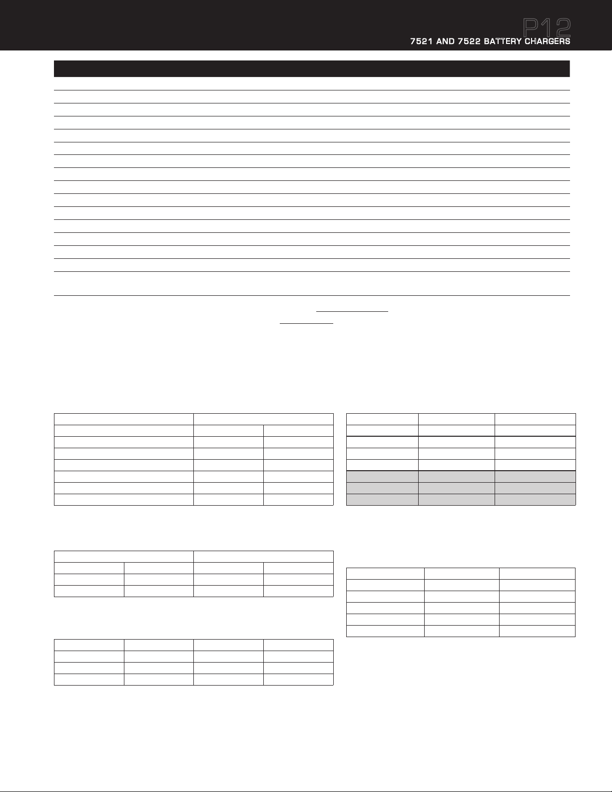
Specifications
7521 AND 7522 BATTERY CHARGERS
P12
7521 7522
Total Output Current 25A 40A
Input AC Current 4.5A @ 100V AC / 2.25A @ 200V AC 7.5A @ 100V AC / 3.75A @ 200V AC
Nominal Output Voltage 12V DC 12V DC
Output Connections 3 positive, 1 negative 3 positive, 1 negative
Universal AC Input Voltage 90V–265V AC 90V–265V AC
Input Frequency Range 45–65 Hz 45–65 Hz
Typical Float Voltage 13.5V DC 13.5V DC
Maximum Available Voltage 16.0V DC 16.0V DC
Output Voltage Accuracy 0.05V DC 0.05V DC
Minimum Operating Temperature −20°C (−4°F) −20°C (−4°F)
Maximum Operating Temperature 70°C (158°F) 70°C (158°F)
Minimum Storage Temperature −30°C (−22°F) −30°C (−22°F)
Maximum Storage Temperature 80°C (176°F) 80°C (176°F)
Warranty 5 Year 5 Year
Battery Types* Flooded, Gel, AGM, TPPL (Thin Plate Pure Lead) Flooded, Gel, AGM, TPPL (Thin Plate Pure Lead)
Recommended for Battery Bank Sizes**
* Consult batter y manufacturer specifications for other battery types to avoid damage. Do not mix battery types.
** Battery bank sizes are recommended for optimal charging efficiency-see bluesea.com/P12 for details. Larger and smaller size banks could charge well, but consume slightly
more power over the charging cycle.
160Ah Minimum, Example: 2 x Group 27
330Ah Maximum, Example: 3 x Group 31
Regulatory
Designed and constructed for compliance to UL-1236 Marine, CSA 22.2 No. 107.2, and ABYC A-31 standards. Ignition Protection per ISO 8846, and SAE J1171.
Meets FCC Part 15, Class B requirements. To view current regulatory specifications visit www.bluesea.com/P12.
220Ah Minimum, Example: 2 x Group 31
440Ah Maximum, Example: 4 x Group 31
Table A: Minimum Recommended Wire Size*
Conductor Length in feet (meters) Charger Rating
25A 40A
6 ft (1.83 meters) 14 AWG (2.5mm²) 8 AWG (10mm²)
10 ft (3.05 meters) 12 AWG (4mm²) 8 AWG (10mm²)
15 ft (4.57 meters) 10 AWG (6mm²) 6 AWG (16mm²)
20 ft (6.09 meters) 8 AWG (10mm²) 6 AWG (16mm²)
25 ft (7.62 meters) 6 AWG (16mm²) 4 AWG (25mm²)
Recommended Battery Fuse
* Based on 3% voltage drop. If fast charge recovery is important, use larger wire. Double the conductor
length entry to get a 1.5% drop, triple the conductor length to get a 1% voltage drop.
30A 60A
Table B: Recommended DC Circuit Protection
Appropriate Fuses and Fuse Holders Charger Rating
Fuse Type Fuse Holder 25A 40A
MRBF Terminal Fuses
AMI®/MIDI® Fuses 7720 Safety Fuse Block 5250 (30A Fuse) 5253 (60A Fuse)
5191 Terminal Fuse Block
5175 (30A Fuse) 5178 (60A Fuse)
Table C: Typical AC Regional Wire Colors
Region Line Neutral Ground (Earth)
North America Black White Green
Europe Brown Blue Green-Yellow
Australia/ New Zealand Brown or Red Blue or Black Green-Yellow
Table D: AC Wire - Circuit Protection Selection Chart
7521 (25A) 7522 (40A)
Input Watts 450 750
120V AC Application 4.5A @ 100V AC 7.5A @ 100V AC
Minimum AC Wire Size 18 AWG (0.75mm²) 16 AWG (1.5mm²)
Circuit Breaker 10A 15A
230V AC Application* 2.25A @ 200V AC 3.75A @ 200V AC
Minimum Wire Size 18 AWG (0.75mm²) 18 AWG (0.75mm²)
Circuit Breaker 5A – 10A 5A – 10A
* Typical of Europe
Table E: Default Voltages by Battery Type
Batteries should match in chemistry, although many AGM’s and flooded batteries are
compatible. Based on 25°C (77°F)
Type Absorb Volts Float Volts
FLA – Flooded Lead Acid 14.5V 13.5V
AGM – Absorbed Glass Mat 14.35V 13.3V
Gel – Gelled Electrolyte 14.1V 13.5V
TPPL – Thin Plate Pure Lead 14.7V
User Adjustable 12.5V Default 12.5V Default
¹ Taken from Odyssey Tech Notes, Northstar operation Manual
13.6V¹
Specifications are subject to change. See bluesea.com/P12 for current information.
5
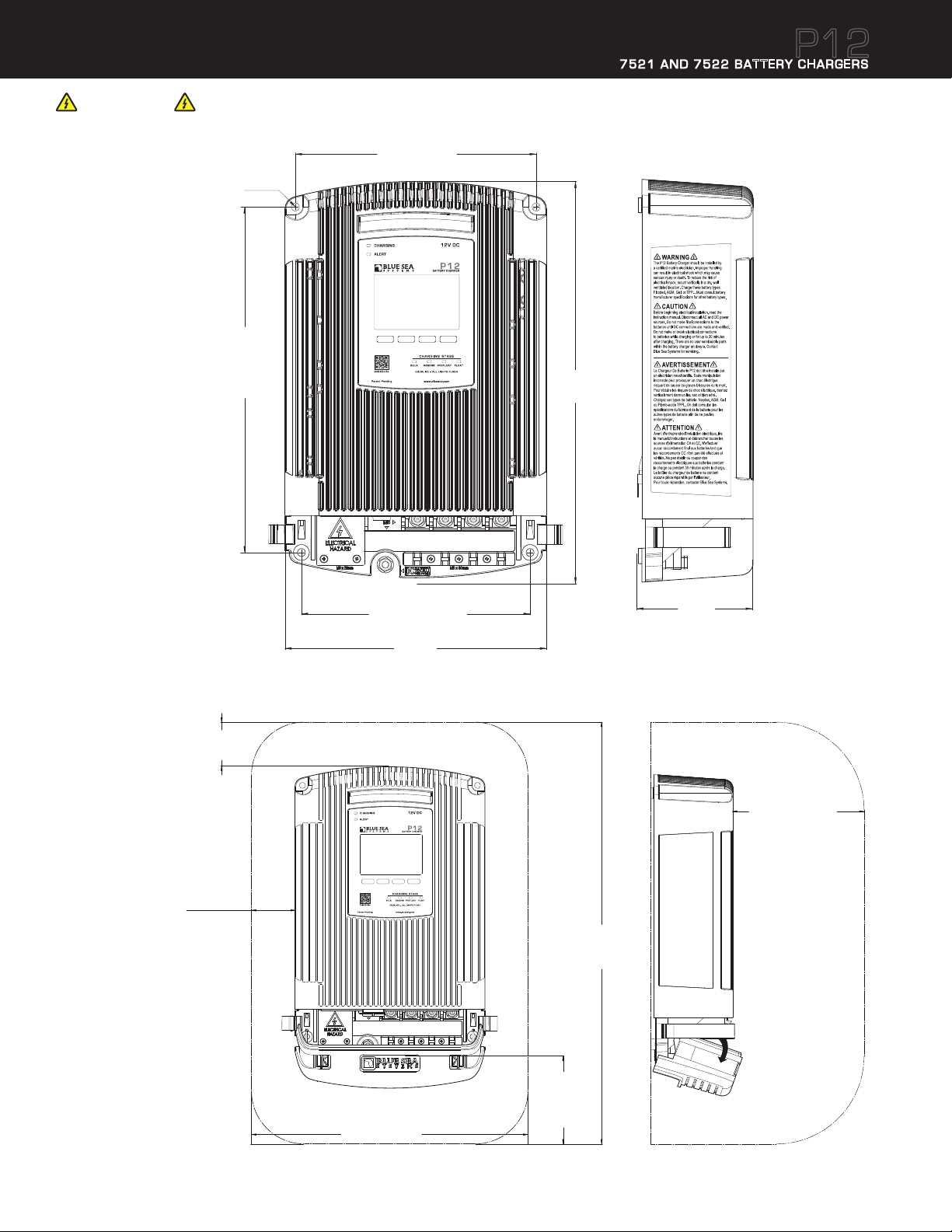
Product Dimensions
7521 AND 7522 BATTERY CHARGERS
WARNING
For drip proof performance, and to meet ABYC requirements, the P12 Battery Charger must be mounted vertically as shown below.
7.80" (198mm)
Top mounting
screw centers
Ø0.3" (6.6mm)
Mounting holes
Clearance for:
M6, 1/4", or #12
mounting hardware
NOTE: Mounting
holes are
not symmetrical
11.18"
(284mm)
Mounting
screw
centers
13.00"
(330.6mm)
P12
Installation Clearances
Recommended
top clearance
"
(50mm)
1.97
Recommended
side clearance
"
(50mm)
1.97
7.40" (188mm)
Bottom mounting
screw centers
8.46"
(215mm)
TOP
Recommended
overall
envelope height
"
(480.6mm)
19.00
3.66"
(93mm)
Recommended
clearance
for cooling fan exhaust.
do not block!
"
(150mm)
5.91
Recommended
clearance
for wire access
Recommended
overall envelope width
12.40
"
(315mm)
6
Specifications are subject to change. See bluesea.com/P12 for current information.
and inlet airflow.
"
(100.2mm)
3.94
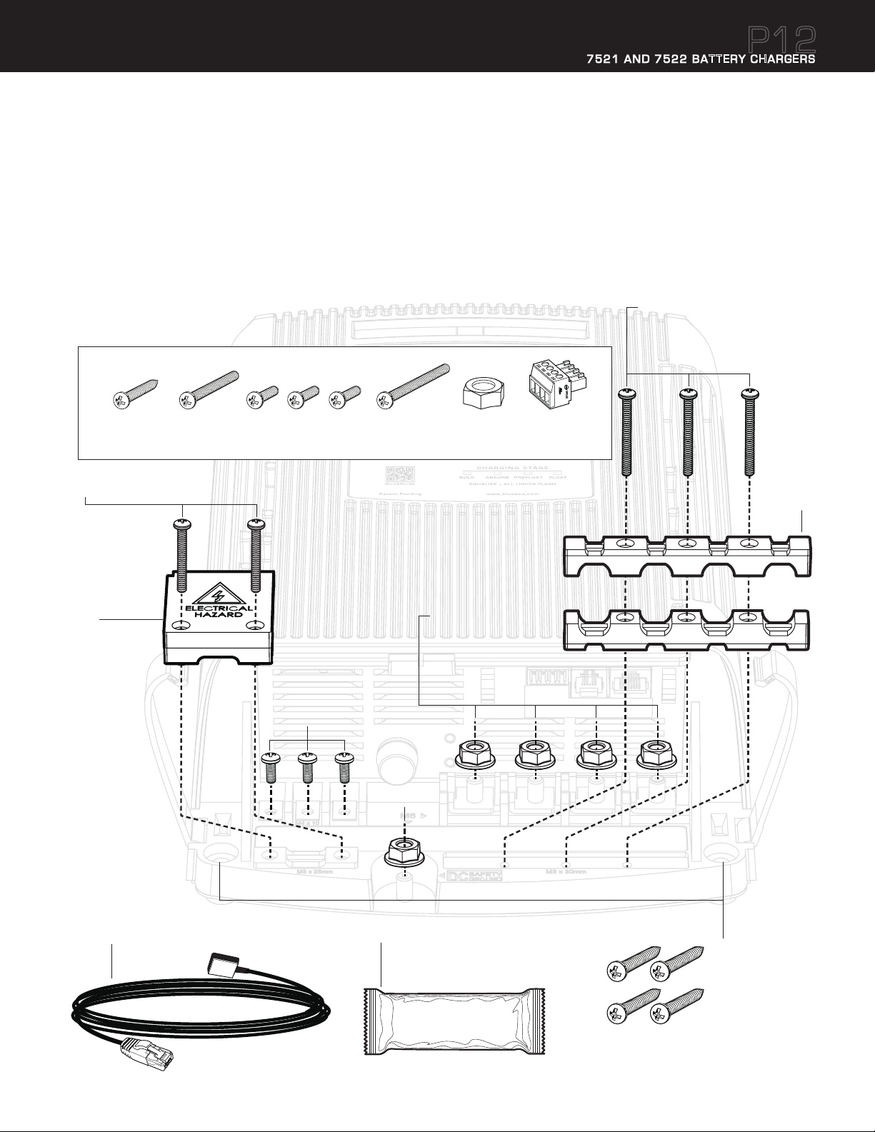
Included Components
1. Four Mounting Screws
2. Two AC Strain Relief and Insulating Cover Screws
3. One AC Strain Relief and Insulating Cover
4. Three AC Termination Screws: AC Line: Gold, AC Neutral: Silver, AC Ground: Green
5. Three DC Strain Relief C-Clamp Screws
6. One DC Strain Relief C-Clamp
7. Four DC Termination Nuts
8. One DC Safety Ground Nut
9. One Battery Temperature Sensor
10. One Packet of Dielectric Grease
11. Accessory Pack Includes:
Accessory Pack
AC Line
Gold
AC Neutral
Silver
AC Ground
Green
7521 AND 7522 BATTERY CHARGERS
P12
5
M3 x 30mm pan-head machine screws
(Use #1 Phillips screwdriver)
Recommended torque:
5–10 in-lb (0.6–1.1 Nm)
#12 x 1-1/4"
sheet metal screw
M3 x 25mm pan-head machine screws (Use #1 Phillips screwdriver)
2
Recommended torque: 5–10 in-lb (0.6–1.1 Nm)
M3 x 25mm
pan-head
machine screw
3
M4 x 10mm
pan-head
machine screws
M4 x 10mm pan-head
machine screws,
(Use #2 Phillips
screwdriver)
Recommended torque:
10–15 in-lb
(1.0–1.8 Nm)
4
M3 x 30mm
pan-head
machine screw
8
M6 serrated
flange hex-nut
7
M6 serrated flange hex-nuts
(Use 10mm socket wrench
with extension)
Recommended torque:
70–80 in-lb (8–9 Nm)
M6 serrated
flange hex-nut
(see #7 above)
Screw terminal
plug for ACR
connection
6
RJ11 connector with peel and stick
9
adhesive, 15 ft (4.6m) long tether
Used for Temperature Sensor and the
10
Optional Accessory P12 Remote Display
Connections (see pages 24–27). View
the MSDS for the Dielectric Grease at
bluesea.com/P12
Dielectric Grease
Specifications are subject to change. See bluesea.com/P12 for current information.
1
#12 x 1-1/4" sheet
metal screws (Use #3
Phillips screwdriver)
77

Supplies Needed
7521 AND 7522 BATTERY CHARGERS
1. AC Wire (see Table D page 5)
NOTE: Wire length must reach from the panel to the battery charger AC Connections with proper routing, support, drip loops, service loops, and termination.
2. DC Wire: Black or Yellow for negative and red for each positive. (see Table A page 5)
NOTE: Yellow is preferred for negative however diagrams are drawn in black for visibility.
3. Fuse holders for connection to each battery. (see Table B page 5)
4. Fuses for fuse holders. (see Table B page 5)
5. Screwdrivers
• Flat blade screwdriver
• Phillips #1 – for AC Termination cover and DC Termination Strain Relief clamp
• Phillips #2 – for AC termination screws
• Phillips #3 – for mounting screws
6. Socket wrench
• 10mm socket with extension and ratchet handle or nut driver – for DC wire terminations
7. Ring terminals
• #8 ring terminals sized for AC/Supply wire gauge (quantity 3)
• ¼” or M6 ring terminals sized for DC wire sizes (quantity 4)
P12
8. Crimping tool or obtain wires that are pre-terminated
9. Appropriate heat shrink if pre-terminated wires were not acquired
8
Specifications are subject to change. See bluesea.com/P12 for current information.
 Loading...