

Page 1
BATTERY CHARGER REMOTE
P12
Scan for
Instructions
PN 7520 / PN 1521
Indicates battery charger stage, alerts, and controls basic
battery charger functions
LED Indicators
• Charging: Quick check for green light conrms charging
• Charge Stage: Displays charging stage including PreFloat for each battery
• Equalize: Indicates when the charger is in equalization mode
• Fan Mode: Indicates charger’s internal fan mode
• Charge Output: Displays the percentage of output current for each battery.
Will also indicate maximum output setting when maximum output is adjusted
to accommodate for AC source limitations.
• Alert: Provides warning and alert status for quick diagnostics
Four Control Buttons
• Fan: User adjustable settings (OFF, LOW, or HIGH)
• Dim/ Alarm: Provides adjustment to brightness of LEDs on display as well
as Silence function for alarms.
• Output: User adjustable charger output when AC source limitations exist
that require lowering the AC current draw.
• Standby: Places P12 Battery Charger into standby mode
GUARANTEE: Blue Sea Systems stands behind its products for as long
as you own them. Find detailed information at www.bluesea.com/about.
For customer service, call 800-222-7617.
Blue Sea Systems Inc. p 360.738.8230
425 Sequoia Drive f 360.734.4195
Bellingham, WA 98226 USA conductor@bluesea.com
www.bluesea.com
additional
product
information
980016790 Rev.001
Warranty
Register your P12 Remote Display at bluesea.com/warranty
Blue Sea Systems stands behind its products for as long as you own them. Blue Sea
Systems will replace or issue a credit for any of its products found to be defective in
materials or manufacture. P12 Battery Chargers and P12 Remote Displays are warranted
for a period of five years from the date of first purchase. No compensation will be allowed
for products not returned to Blue Sea Systems for analysis, nor will compensation be made
for labor required to replace any defective product. Please contact Customer Service for an
RMA number prior to shipping any product back to Blue Sea Systems. Blue Sea Systems
cannot accept liability for damage due to the use of the P12 Battery Charger.
“Date of first purchase” means:
1. The date on which the product was purchased by the first retail customer
2. The date on which the first retail customer purchases a vessel on which the product
was installed
Blue Sea Systems will (at its sole discretion) repair or replace any product which is:
1. Proven to be defective in materials or workmanship
2. Returned to Blue Sea Systems (or its agent) during the warranty period in accordance
with this warranty
The replacement battery charger may be new or refurbished in as-new condition. Such
repair or replacement will be the sole remedy by Blue Sea Systems under this warranty.
Any repaired or replacement product will be warranted in accordance with this warranty for
the unexpired balance of the warranty period on the original product.
Specications
Minimum Operating Temperature −20°C (−4°F)
Maximum Operating Temperature 60°C (140°F)
Minimum Storage Temperature −30°C (−22°F)
Maximum Storage Temperature 70°C (158°F)
Electrical Specication:
On State Operating Current <300mA sourced from charger
Communications:
Protocol Proprietary
Maximum Cable Length 150 ft (45.7 m)
Cable Cat5e (Standard US)
Mounting Hole Cutout 1-1/4" (31.75 mm)
Dimensions Height: 3.01" (76.56 mm)
Width: 4.15" (105.46 mm)
Depth: .95" (24.01 mm)
Mounting Hardware Included #6 Screws
Regulatory
Surface Mount Gasket creates an IP67 waterproof seal on unit face--temporary
immersion for 30 minutes.
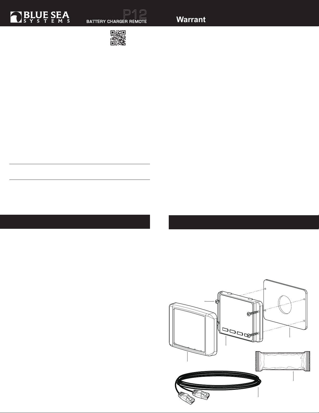
Included Components
1. Mounting Screws: (4) #6 x 1" pan-head sheet metal screws (#2 Phillips screwdriver)
2. Cover
3. Remote Assembly
4. Mounting Gasket
5. 25 ft (7.6 m) Cat5e Cable
6. Dielectric Grease: Blue Sea Systems recommends using a high quality dielectric grease
for remote control connection. View the MSDS for the Dielectric
Grease at bluesea.com/P12
1
4
3
2
6
5
1 of 4
Page 2
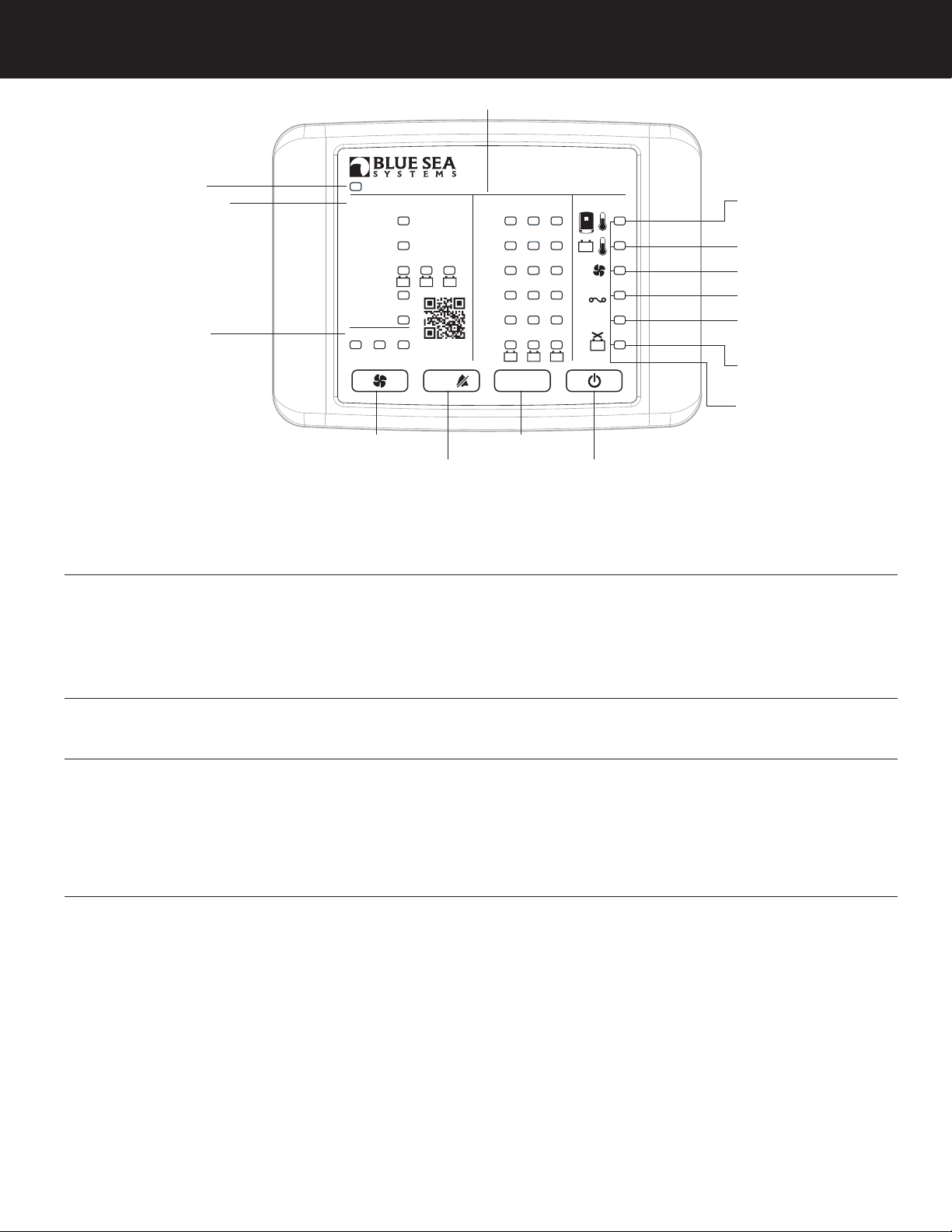
Display Indicators
4. Charge Output
1. Charging
2. Charge Stage
BULK
ABSORB
PREFLOAT
FLOAT
EQUALIZE
3. Fan Mode
CHARGING
Charge Stage
BULK
ABSORB
PREFLOAT
FLOAT
EQUALIZE
Fan Mode
1
HIGHLOWOFF
13. Fan
2
QuickGuide
7520 BATTERY CHARGER REMOTE
Charge Output
100%
75%
50%
3
25%
10%
<5%
DIM /
OUTPUT
15. OUTPUT
14. DIM/Alarm
1. Charging:
SOLID ON (Green): Indicates Charging mode and will operate according to its charging stage.
BLINKING (Green): Transitioning from Standby to a Charging state.
OFF: Standby mode - will not charge a battery or supply current to loads.
2. Charge Stage:
Bulk-BLINKING (Green): Indicates Bulk stage on all batteries
Absorb - BLINKING (Green): Indicates Absorb stage on all batteries
Prefloat*- SOLID ON (Green): Indicates PreFloat stage on any of three batteries
Float - SOLID ON (Green): Indicates Float stage on all batteries
Equalize:
BLINKING (Yellow): Indicates Equalize stage on any of three battery branches.
2
1
P12
Alert
DC
AC
3
16. Standby
5. Thermal Regulation and
6. Internal Temperature Sensor
7. Battery Temperature Sensor
8. Fan
9. DC Fuse
10. AC Input Voltage
Too High or Low
11. Reverse Polarity
or Short Circuit
12. Hardware Failure,
DC Output Voltage Too High,
or Equalization Overload
3. Fan Mode:
SOLID ON (Green): Indicates fan LOW or HIGH mode.
SOLID ON (Yellow): Indicates fan OFF mode.
BLINKING (Yellow): Indicates that the fan is OFF and the charger is limiting its output current to protect from eventual overheating. If full output is desired, the
Fan Mode needs to be set to LOW or HIGH to keep the charger cool. If the fan is OFF the charger will limit its output based on its internal
temperature sense.
4. Charge Output:
SOLID ON (Green): Charge Output LEDs are used to monitor the output on three batteries and limit the output using the output button. In normal operation, the Charge
Output LEDs show the percentage of the absolute maximum current on each battery. The range of each individual percentage is as follows:
<5%: 0% ≥ output < 5%
10%: 5% ≥ output < 17.5 %
25%: 17.5% ≥ output < 37.5%
50%: 37.5% ≥ output < 62.5%
75%: 62.5% ≥ output < 87.5%
100%: 87.5% ≥ output < 100%
BLINKING (Green): Indicates that the charger is limiting its output. There are two situations where this could occur:
1) The output of the charger is being limited per the user’s output setting.
2) The charger is limiting output to protect itself from overheating. In this situation, the Charge Output will blink alongside the yellow Thermal Regulation Alert.
See P12 Batter y Charger User Manual for more details.
2 of 4
Page 3

Alerts and Diagnostics
5. Thermal Regulaton:
SOLID ON (Yellow): The charger temp output limit LED indicator will blink to notify the user that the charger is limiting its output to protect itself from eventual overheating. The
most common correction for this state is to increase the fan speed to High. If the fan speed is already set to High check for blockage around the fan vent that can be removed.
If the condition persists, it is advisable to reposition the battery charger in a cooler, more ventilated location. See P12 Battery Charger User Manual page 20 for more details.
6. Internal Temperature Sensor:
BLINKING (Red): Indicates a problem with the thermistor temperature sense internal to the charger. If that is the case, the charger will immediately go into standby mode.
This form of temperature alert can not be corrected by the user. Contact Blue Sea Systems for further information regarding internal temperature sensor alerts.
7. Battery Temperature Sensor:
BLINKING (Red): Indicates the battery temperature is out of range. The charger will not charge a battery exceeding temp limits and will therefore go into standby
mode immediately. The remote will signal its alarm. If at any point the temperature sensor records a temperature beyond the defined temperature limits, the battery
charger will display the Battery Temperature Alert Screen. In this situation all battery charging will stop until the proper battery temperature is restored. Normal operation
will not commence unless two degrees within the temperature parameters. See P12 Battery Charger User Manual page 20 for more details.
8. Fan:
BLINKING (Red): Indicates the chargers’ internal fan is not working properly. See P12 Battery Charger User Manual page 20 for more details.
9. DC Fuse:
BLINKING (Red): Indicates the chargers’ internal DC fuse is blown. The P12 Battery Charger has two internal DC fuses that are not accessible by the user. Disconnect AC
power and all battery connections. The battery charger will require servicing by Blue Sea Systems. No attempts should be made to replace the fuses by the user. Contact Blue
Sea Systems for further instructions regarding DC fuse replacement.
10. AC Input Voltage Too High or Low:
BLINKING (Red): Indicates charger AC power is out of range. See P12 Battery Charger User Manual page 21 for more details.
11. DC Reverse Polarity or Short Circuit:
BLINKING (Red): Indicates a reverse polarity or short circuit condition is present on the DC output. The remote will signal its alarm. See P12 Battery Charger User Manual
page 20 for more details.
12. Hardware Failure, DC Output Voltage Too High, Equalization Overload: ALL ALERT LEDs BLINKING (Red): Indicates fault state.
Go to the P12 Battery Charger to see the pop-up screen explaining the reason.
Buttons
13. Fan Mode:
Press to scroll through fan mode selections OFF, LOW or HIGH.
See P12 Battery Charger User Manual for more details.
14. Dim /Alarm:
- Normal operation: Press to Dim LED brightness.
- Fault Condition: Press once to silence Alarm buzzer.
15. Output:
Limits the charger’s output to a certain percentage of its absolute maximum. Press the output button once to show the current output setting on Charge Output LEDs. Press
again to scroll through settings. The setting is shown via a row of solid LEDs correlating to the percentage. The user can set the output from 100% down to 25%.
16. Standby:
Puts the charger in Standby mode. If the charger is in charging mode, press once to go to Standby. If in Standby, press once to start charging again.
A blinking charging LED indicates the charger is transitioning from Standby to Charging.
See P12 Battery Charger User Manual for more details.
3 of 4
Page 4

Cable Connection
The P12 Battery Charger Remote uses one Cat5e cable for communication and power.
P12 Battery Charger
RJ45 Port
P12 Battery
Charger Remote
Dimensioned Drawing
2.52"
(63.88mm)
1.50"
(38.10mm)
Blue Sea Systems Inc.
425 Sequoia Drive
Bellingham, WA 98226 USA
p 360.738.8230
f 360.734.4195
conductor@bluesea.com
www.bluesea.com
980016790 Rev.001
4.15"
(105.46mm)
2.90"
(73.70mm)
3.69"
(93.66mm)
Mounting Hole Cutout
Ø1-1/4"
(31.75mm)
3.01"
(76.56mm)
Clearance holes
for #6 screws
0.57"
(14.36mm)
0.38"
(9.65mm)
4 of 4
 Loading...