

Page 1
It is not possible within the scope of these
instructions to fully acquaint the installer
with all the knowledge of electrical systems
that may be necessary to correctly install
this product. If the installer is not
knowledgeable in electrical systems we
recommend that an electrical professional
be retained to make the installation.
Installation
Warning
Before starting, disconnect the main
1. Disconnect all AC and DC power
ucts
positive cable from all batteries to eliminate
the possibility of a short circuit while
installing the meter. Also disconnect the AC
shore power cord from the boat to eliminate
the possibility of electrocution from AC
wiring near the DC ammeter.
Select a mounting location which is
protected from water on the meter front and
back and is not in an area where fl ammable
vapors from propane, gasoline or lead acid
batteries accumulate. The meter is not
ignition protected and may ignite such
vapors. There are two mounting methods
for the 8038 and 8005 ammeters, surface
mount or panel mount.
2. Select mounting location
Document 9289 Rev.D
PN 8005
0-15 Amperes PN 8038
0-25 Amperes PN 8005
Marine Electrical Prod
Analog DC Ammeter
Meter Specifi cations
Input Voltage: 8 Volts DC to 16 Volts DC
Amperage Draw: 1 Milliamp at full scale
Display: Analog scale
Accuracy: 3% of scale range
PN Inches Millimeters
It is not possible within the scope of these
instructions to fully acquaint the installer
with all the knowledge of electrical systems
that may be necessary to correctly install
this product. If the installer is not
knowledgeable in electrical systems we
recommend that an electrical professional
be retained to make the installation.
Installation
Warning
Before starting, disconnect the main
1. Disconnect all AC and DC power
Blue Sea Systems Inc.
Any Blue Sea Systems product with which
a customer is not satisfi ed may be returned
for a refund or replacement at any time.
Face Width: 8038 2 50.80
8005 2-1/2 63.50
Mounting Hole: 8038 1-1/2 38.10
8005 1-7/8 47.60
Guarantee
positive cable from all batteries to eliminate
the possibility of a short circuit while
installing the meter. Also disconnect the AC
shore power cord from the boat to eliminate
the possibility of electrocution from AC
wiring near the DC ammeter.
Select a mounting location which is
protected from water on the meter front and
back and is not in an area where fl ammable
vapors from propane, gasoline or lead acid
www.bluesea.com
E-mail conduct @ bluesea.com
Phone (360) 738-8230 Fax (360) 734-4195
425 Sequoia Drive Bellingham, WA 98226 USA
batteries accumulate. The meter is not
ignition protected and may ignite such
vapors. There are two mounting methods
for the 8038 and 8005 ammeters, surface
mount or panel mount.
2. Select mounting location
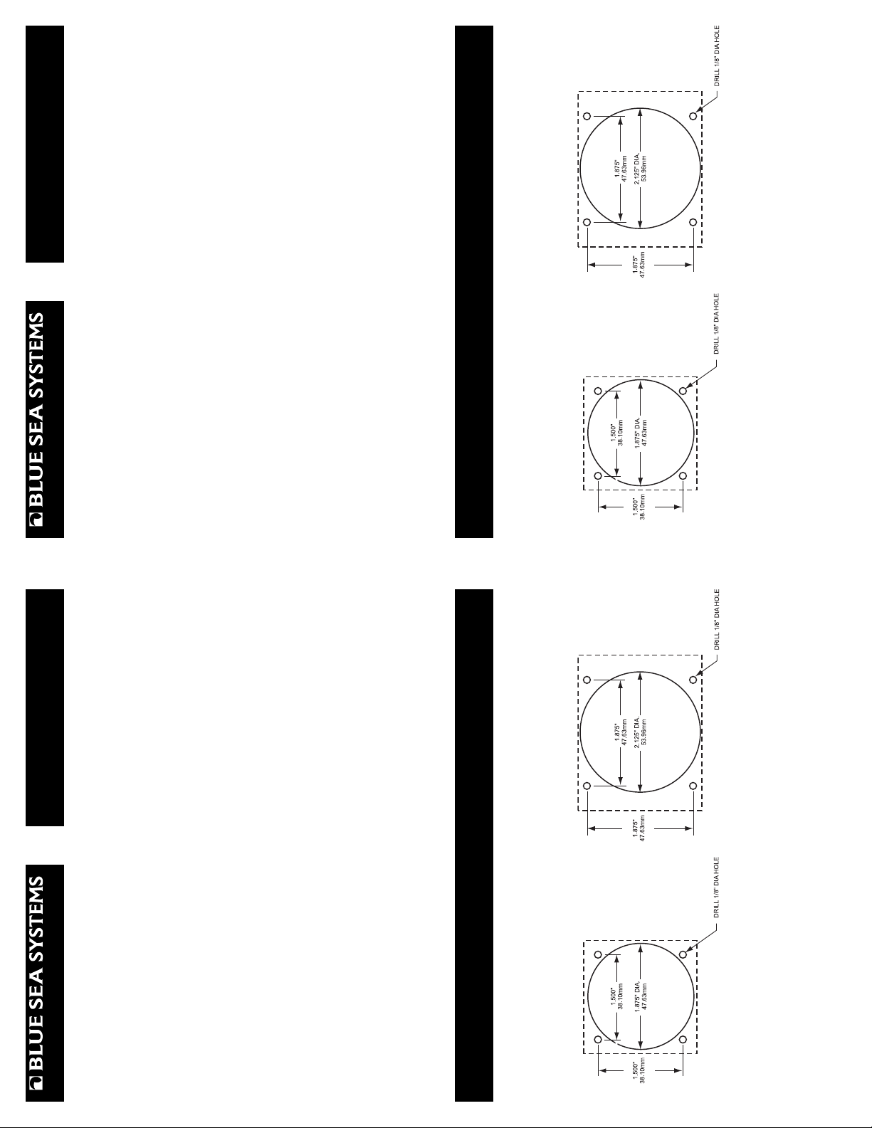
Surface Mount: Drill fi ve clearance holes a shown below. The part number of the meter will
determine the size and location of the clearance holes. Use the nuts and washers supplied in the
accessory package to secure the four mounting studs to the mounting surface. This method will
Installation (continued)
work on mounting surfaces up to 5/8” thick.
(
PN 8038
Panel Mount: For thicker mounting surfaces, the meter can be mounted into a 0.125” thick
panel. Blue Sea Systems offers meter mounting panels for our standard size meters only. For
part number 8005 use part number 8013 to mount a single meter or part number 8014 to mount
two meters.
PN 8005
ucts
0-15 Amperes PN 8038
Marine Electrical Prod
Analog DC Ammeter
0-25 Amperes PN 8005
Meter Specifi cations
Input Voltage: 8 Volts DC to 16 Volts DC
Amperage Draw: 1 Milliamp at full scale
Display: Analog scale
Accuracy: 3% of scale range
PN Inches Millimeters
Face Width: 8038 2 50.80
8005 2-1/2 63.50
Mounting Hole: 8038 1-1/2 38.10
Document 9289 Rev.D
Blue Sea Systems Inc.
Any Blue Sea Systems product with which
a customer is not satisfi ed may be returned
for a refund or replacement at any time.
8005 1-7/8 47.60
Guarantee
www.bluesea.com
E-mail conduct @ bluesea.com
Phone (360) 738-8230 Fax (360) 734-4195
425 Sequoia Drive Bellingham, WA 98226 USA
Surface Mount: Drill fi ve clearance holes a shown below. The part number of the meter will
determine the size and location of the clearance holes. Use the nuts and washers supplied in the
accessory package to secure the four mounting studs to the mounting surface. This method will
Installation (continued)
work on mounting surfaces up to 5/8” thick.
(
PN 8038
Panel Mount: For thicker mounting surfaces, the meter can be mounted into a 0.125” thick
panel. Blue Sea Systems offers meter mounting panels for our standard size meters only. For
part number 8005 use part number 8013 to mount a single meter or part number 8014 to mount
two meters.
Page 2

Panel Mount
Surface Mount
PN 8005
PN 8038
Installation (continued)
The 8005 and 8038 ammeters utilize an internal shunt as their current sensing device. The
3. Wire Selection
Panel Mount
Surface Mount
PN 8005
nature of current measurement is that the full current to be measured must fl ow through the
sensing device. Therefore it is necessary to run wire to the meter of suffi cient size to carry the
current to be measured. The wire size will vary depending on the total distance of the wire run,
the TOTAL length of the positive and negative wires. There must be a fuse or circuit breaker in
the positive wire lead to the meter. Choose a wire and fuse based on the table below.
Wire Run (Feet) 10 15 20 25 30 35 40 50 60 70 80
* These maximum allowable fuse sizes (Maximum allowable wire amperages) are for wires
outside of engine spaces. Wires inside engine spaces have a maximum allowable wire
amperage of 15% less, therefore maximum allowable fuse sizes must be reduced by 15%.
Notice the difference between a serial connection and a parallel connection in the diagram
below. Internal shunt ammeters are mounted in a serial confi guration.
Wire Size (AWG) 10 10 8 6 6 6 4 4 2 2 2
Maximum Fuse (A)* 60 60 80 120 120 120 160 160 210 210 210
4. Connection
The 8005 and 8038 ammeters are calibrated at the factory and recalibration should never be
necessary. However, if adjustment does become necessary the needle may be reset to the zero
mark. In the center of the black area on the meter front is an adjustment screw. This screw
activates a small cam that defl ects the meter needle slightly to adjust the needle position. Using
a small screw driver, turn the screw no more than 90 degrees right or left, as necessary. DO
Choose the site in the circuit to be measured where the meter is to be installed. It may be either
in the positive or negative side of the circuit.
Break the circuit at this point and install the meter. Be certain to attach the wire end nearest the
positive side of the circuit to the meter terminal marked + (positive). Attach the wire nearest the
negative side of the circuit to the meter terminal marked - (negative)
NOT ROTATE THE ADJUSTMENT SCREW THROUGH 360 DEGREES.
5. Calibration
Installation (continued)
PN 8038
The 8005 and 8038 ammeters utilize an internal shunt as their current sensing device. The
nature of current measurement is that the full current to be measured must fl ow through the
sensing device. Therefore it is necessary to run wire to the meter of suffi cient size to carry the
current to be measured. The wire size will vary depending on the total distance of the wire run,
3. Wire Selection
the TOTAL length of the positive and negative wires. There must be a fuse or circuit breaker in
the positive wire lead to the meter. Choose a wire and fuse based on the table below.
Wire Run (Feet) 10 15 20 25 30 35 40 50 60 70 80
* These maximum allowable fuse sizes (Maximum allowable wire amperages) are for wires
outside of engine spaces. Wires inside engine spaces have a maximum allowable wire
amperage of 15% less, therefore maximum allowable fuse sizes must be reduced by 15%.
Notice the difference between a serial connection and a parallel connection in the diagram
below. Internal shunt ammeters are mounted in a serial confi guration.
Wire Size (AWG) 10 10 8 6 6 6 4 4 2 2 2
Maximum Fuse (A)* 60 60 80 120 120 120 160 160 210 210 210
4. Connection
The 8005 and 8038 ammeters are calibrated at the factory and recalibration should never be
necessary. However, if adjustment does become necessary the needle may be reset to the zero
mark. In the center of the black area on the meter front is an adjustment screw. This screw
activates a small cam that defl ects the meter needle slightly to adjust the needle position. Using
a small screw driver, turn the screw no more than 90 degrees right or left, as necessary. DO
Choose the site in the circuit to be measured where the meter is to be installed. It may be either
in the positive or negative side of the circuit.
Break the circuit at this point and install the meter. Be certain to attach the wire end nearest the
positive side of the circuit to the meter terminal marked + (positive). Attach the wire nearest the
negative side of the circuit to the meter terminal marked - (negative)
NOT ROTATE THE ADJUSTMENT SCREW THROUGH 360 DEGREES.
5. Calibration
 Loading...