

Page 1
Marine Electrical Prod
ucts
Panel Backlight System
PN: 8069
Features
• Easily installed in Blue Sea Systems’
power distribution panels
• Unique 10 position design that can be
shortened for 8, 5, and 3 position
panels
• Connects to 12 or 24 Volt DC source
via two 12” 18 AWG wire leads.
Specifi cations
Current Draw: 5mA / LED
Power Supply: 12/24V DC
Guarantee
Any Blue Sea Systems’ product with which
a customer is not satisfi ed may be returned
for a refund or replacement at any time.
425 Sequoia Drive Bellingham, WA 98226 USA
Phone (360) 738-8230 Fax (360) 734-4195
Blue Sea Systems Inc.
E-mail conduct @ bluesea.com
www.bluesea.com
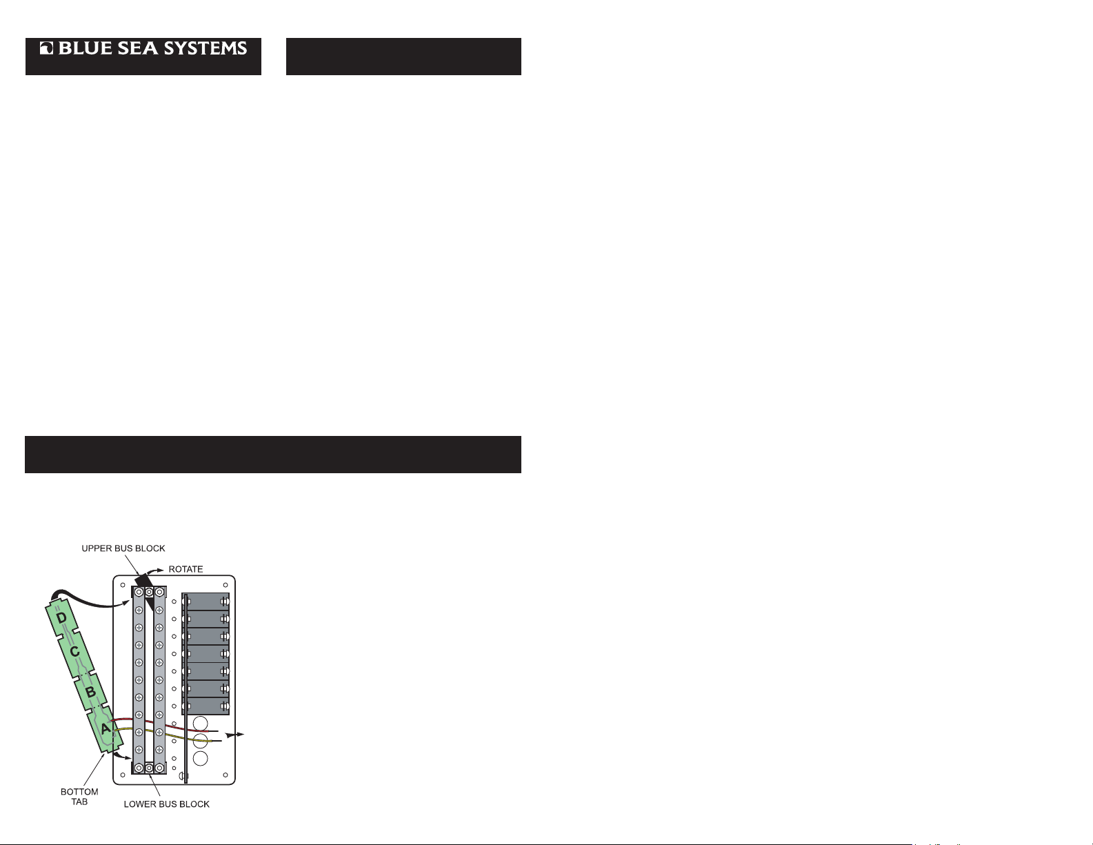
Installation (continued)
With the green LED’s facing the panel,
insert the bottom tab nearest the wire leads
into the slot and rotate the lower block back
into position. Lightly tighten both bus
screws.
Installation
1. Installation of backlight board
The backlight board is mounted between
the 2 black bus support blocks on the back
of the panel as shown.
The backlight board can be easily
shortened to fi t all Blue Sea Systems
backlightable panels. For panels with 8”
buses no shortening of the board is
necessary.
For 6-1/2” buses, snap off section D
furthest from the wire leads.
For 4-1/4” buses snap off section B and C.
For 2-3/4” buses snap off section B, C
and D. It may be necessary to lightly sand
the end to remove any rough edges.
Loosen the single screw retaining the lower
bus block exactly 1 turn. Then loosen the
upper screw 2 turns.
Document 9964 Rev.E
2. Electrical Connection
For DC Panels
Connect the yellow negative wire to the
panel negative bus.
To activate the label lights by the boat’s
battery switch, connect the red positive
wire to the DC panel positive bus.
To activate the label lights by an
independent switch or breaker, connect the
red positive wire to the load side of the
switch or breaker
For AC Panels
The backlight board is a DC device. When
installing it in an AC panel both wire leads
must be connected to an appropriate DC
source and ground.
Connect the yellow negative wire to a DC
ground. Connect the red positive wire to
any DC positive supply, usually a switch
that controls the vessel’s other nighttime
illumination.
 Loading...