

Page 1

Marine Electrical Prod
ucts
AC Main Source Selector Panels
PN 8132 / PN 3132 / PN 8161 / PN 3161
Panel Specifi cations
Material: 0.125” 5052-H32 Aluminum Alloy
Primary Finish: Chemical Treatment per Mil Spec C-5541
Final Panel Finish: Graphite color 2 part textured Polyurethane
Circuit Breakers: Double Pole Carlingswitch B Series AC / DC
Magnetic Breakers 65VDC/277VAC Maximum
Amperage Rating: PN 8132 / 3132 is rated for 16 amp service
PN 8161 / 3161 is rated for 32 amp service
Voltage Rating: Panel is rated for 230 volts AC and is so marked in
Inches Millimeters
Overall Dimensions: 5-1/4 x 3-3/4 133.40 x 95.30
Mounting Centers: 4-7/16 x 2-15/16 112.70 x 74.60
Standards: This panel, when properly installed, complies with
The Purpose of the AC Main Source Selector Panel
Alternating Current (AC) power changes polarity 60 times per second in
the US, Canada and Latin America and 50 times per second in Europe.
This is the frequency of the power and is referred to as Hertz (or the now
outdated term “cycle”). Because of this alternating nature of AC power,
two live sources of AC power, such as shore power and inverter power,
or shore power and a generator, cannot be electrically connected. The
AC Main Source Selector panel is designed to connect two sources of
AC power to a common circuit while preventing both sources from being
connected to the circuit simultaneously.
order to comply with ABYC standards
all applicable Standards and Recommended
Practices of the American Boat and Yacht Council
as well as United States Coast Guard 33 CFR Sub
Part 1.
Document 9811 Rev.I
WARNING
@ It is not possible within the scope of these instructions to fully acquaint
the installer with all the knowledge of electrical systems that may be
necessary to correctly install this product. If the installer is not
knowledgeable in electrical systems we strongly recommend that an
electrical professional be retained to make the installation.
@ If either the panel front or back is to be exposed to water it must be
protected with a waterproof shield.
@ The panels must not be installed in explosive environments such as
gasoline engine rooms or battery compartments as the circuit breakers
are not ignition proof.
@ The vessel’s shore power cord must be disconnected form shoreside
power before installing this electrical panel.
@ If an inverter is installed on the vessel its power leads must be
disconnected at the battery before the panel installation. Be aware that
many inverters have a “sleep mode” in which their voltage potential
may not be detectable with measuring equipment.
@ If an AC Generator is installed aboard it must be stopped and rendered
inoperable before the panel is installed.
@ Verify that no other AC source is connected to the vessel’s wiring
before the panel is installed.
Guarantee
Any Blue Sea Systems product with which a customer is not satisfi ed
may be returned for a refund or replacement at any time.
Blue Sea Systems Inc. Phone (360) 738-8230
425 Sequoia Drive Fax (360) 734-4195
Bellingham, WA 98226 USA E-mail conductor@bluesea.com
www.bluesea.com
Installation
1. Disconnect all AC and DC power
Disconnect all AC power originating on or off the vessel. This includes
inverters, generators, shore power attachments and any other device
capable of supplying AC power to the ship’s circuits.
Disconnect the main positive DC cable from all batteries to eliminate
the possibility of a short circuit and to disable the inverter while
installing the distribution panel.
2. Select mounting location and cut opening
If this panel is to serve as your main shore power disconnect circuit
breaker, select a location which is not more then 10 feet from the shore
power inlet or the electrical attachment point of a permanently installed
shore power cord as measured along the conductors of the feed wires.
If it is more then 10 feet, additional fuses or circuit breakers must be
installed within 10 feet of the shore power inlet.
Select a mounting location which is protected from water on the panel
front and back and is not in an area where fl ammable vapors from
propane, gas or lead acid batteries accumulate. The circuit breakers
used in marine electrical panels are not ignition protected and may
ignite such vapors.
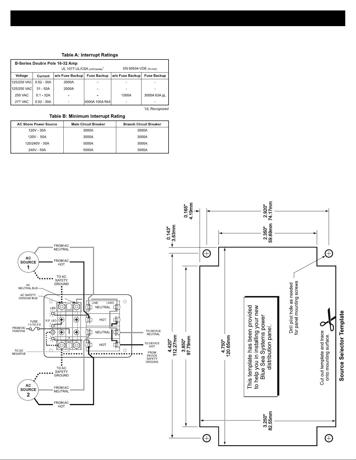
Using the panel template provided, make a cut out in the mounting
surface where the distribution panel is to be mounted. Do not yet
fasten the panel to the mounting surface.
3. Install source 1, source 2 and output wires
Install the feed wires from AC source 1 and AC source 2. Install the
output wires. Refer to the wire sizing chart to select the correct wire
size. Connect the black AC hot, white AC neutral and green AC safety
ground as shown in the illustration.
Do not confuse the neutral current carrying wires (sometimes called
ground) with the green normally non-current carrying wires (sometimes
called grounding). These two wires must be connected only at the
source of power, nowhere else.
If the feed wires are from the shore power inlet or the electrical
attachment point of a permanently installed shore power cord and the
inlet or attachment point is more then 10 feet from this panel, additional
fuses or circuit breakers must be installed within 10 feet of the shore
power inlet. The measurement is made along the conductors.
Wire sizing chart
Use the wire sizing chart below to determine the proper branch and
feed circuit wire sizes.
Note: This chart assumes wire with 105° C insulation rating
and no more than 2 conductors are bundled.
Not suitable for sizing flexible shore power cords.
Page 2
Installation (continued)
4. Interrupt Ratings
If complete ABYC compliance is desired, verify that the circuit breaker
supplied in this panel as shown in Table A meets the interrupt rating
requirements of Table B.
5. Installation of Backlight System
The backlight board is a DC device. When installing it in an AC panel
both wire leads must be connected to an appropriate DC source and
ground.
Connect the yellow negative wire to a DC ground. Connect the red
positive wire to any DC positive supply, usually a switch that controls
the vessel’s other nighttime illumination.
7. Testing
@Connect the vessel’s shore power and verify the Reverse Polarity
light is not illuminated. If the red Reverse Polarity light is on then
either the hot and ground or the hot and neutral wires have been
crossed. Starting at the panel, trace the connections back as far
as necessary to locate the error.
@Using a multimeter where the power source is connected to the
panel verify:
a. 230 volts between hot and neutral
(nominal, this may vary depending on source voltage)
b. 230 volts between hot and ground.
c. 0 volts between neutral and ground.
Related Products from Blue Sea Systems
• PanelBack Insulating Covers
• High Amperage Fuses and Circuit Breakers for positive feed wires
• High Amperage Battery Switches
• Terminal Blocks and Common Bus Connectors
• AC Distribution Panels
• DC Distribution Panels
• AC and DC Digital and Analog Voltmeters and Ammeters
Useful Reference Books
Calder, Nigel, 1996: Boatowner’s Mechanical and Electrical Manual,
2nd edition, Blue Ridge Summit, PA: TAB Books, Inc.
Wing, Charlie, 1993: Boatowner’s Illustrated Handbook of Wiring,
Blue Ridge Summit, PA: TAB Books, Inc.
6. Apply circuit labels and mount panel
Apply a label for each circuit form the 10 basic labels provided. Fasten
the panel to the mounting surface.
Wiring Diagram
AC Source Selector Panel
PN 8132 / PN 3132 / PN 8161 / PN 3161
 Loading...