

Blue Sea Systems AC Rotary Switch Panel 2 Positions + OFF, 2 Pole User Manual
Marine Electrical Prod
ucts
AC Rotary Switch Panel
2 Positions + OFF, 2 Pole
Features
• Switches 2 - 230 V AC Sources
• Compact solution when circuit protection is provided elsewhere
• Allows connecting one of two different AC sources to one circuit
• Heavy duty industrial rated switches
• Intuitive function - One handed operation
• Green power available LED indicators
• Red reverse polarity LED indicators
• UL listed switches
Panel Specifi cations
Voltage Rating: Panels are rated for 230 volts AC
Amperage Rating:
PN 8357 is rated for 65 amp maximum service
Panel Material: 0.125” 5052-H32 Aluminum Alloy
Primary Finish: Chemical Treatment per Mil Spec C-5541
Final Panel Finish: Graphite color 2 part textured Polyurethane
Maximum Wire Size: PN 8359 10 AWG
PN 8357 6 AWG
Minimum Wire Size: PN 8359 14 AWG
PN 8357 12 AWG
Terminal Recommended Torque:
PN 8359 12 lb-in.
PN 8357 40 lb-in.
PN Inches Millimeters
Overall Dimensions: 8357/8359 5-1/4 x 3-3/4 133.35 x 95.25
Mounting Centers: 8357/8359 4-7/16 x 2-15/16 112.71 x 74.61
Mounting Depth: 8359 2 50.80
8357 3 76.20
PN 8357 / PN 8359
PN 8359 is rated for 32 amp maximum service
Document 6335 Rev.A
WARNING
@ It is not possible within the scope of these instructions to fully acquaint
the installer with all the knowledge of electrical systems that may be
necessary to correctly install this product. If the installer is not
knowledgeable in electrical systems we strongly recommend that an
electrical professional be retained to make the installation.
@ If either the switch front or back is to be exposed to water it must be
protected with a waterproof shield.
@ The switch must not be installed in explosive environments such as
gasoline engine rooms or battery compartments as the switches
are not ignition proof.
@ The vessel’s shore power cord must be disconnected form shoreside
power before installing this electrical switch.
@ If an inverter is installed on the vessel its power leads must be
disconnected at the battery before the panel installation. Be aware that
many inverters have a “sleep mode” in which their voltage potential
may not be detectable with measuring equipment.
@ If an AC Generator is installed aboard it must be stopped and rendered
inoperable before the switch is installed.
@ Verify that no other AC or DC source is connected to the vessel’s
wiring before the switch is installed.
Guarantee
Any Blue Sea Systems product with which a customer is not satisfi ed
may be returned for a refund or replacement at any time.
Blue Sea Systems Inc. Phone (360) 738-8230
425 Sequoia Drive Fax (360) 734-4195
Bellingham, WA 98226 USA E-mail conductor@bluesea.com
www.bluesea.com
Installation
1. Disconnect all AC and DC power
Disconnect all AC power originating on or off the vessel. This includes
inverters, generators, shore power attachments and any other device
capable of supplying AC power to the ship’s circuits.
Disconnect the main positive DC cable from all batteries to eliminate
the possibility of a short circuit and to disable the inverter while
installing the switch.
2. Select mounting location and cut opening
Select a mounting location which is protected from water on the front
and back of the switch and is not in an area where fl ammable vapors
from propane, gas or lead acid batteries accumulate. AC rotary
switches are not ignition protected and may ignite such vapors.
Using the panel template provided, make a cut out in the mounting
surface where the distribution panel is to be mounted. Do not yet
fasten the panel to the mounting surface.
3. Install source 1, source 2 and output wires
Install the feed wires from AC Shore Power and AC Generator. Install
the output wires. Refer to the wire sizing chart to select the minimum
wire size. Connect the brown AC hot, light blue AC neutral and green
AC safety ground as shown in the illustration. To avoid excess wire
temperatures when cooling may be limited, we recommend using at
least 12 gauge wire for 30A and 8 gauge wire for 50A.
Do not confuse the neutral current carrying wires (sometimes called
ground) with the green normally non-current carrying wires (sometimes
called grounding). These two wires must be connected only at the
source of power, nowhere else.
A double pole circuit breaker must be installed within 10 feet of the
shore power inlet, ahead of this switch. The measurement is made
along the conductors. The switch provides switching, but does not
provide circuit protection. It is not a substitute for a main circuit breaker.
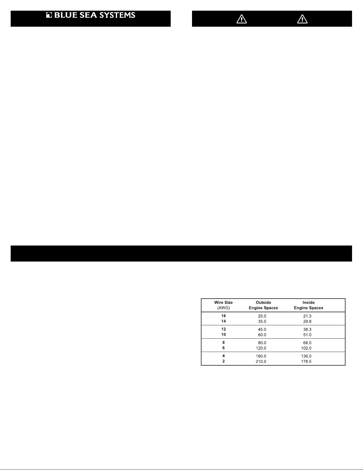
Wire sizing chart
Use the wire sizing chart below to determine the minimum branch and
Note: This chart assumes wire with 105° C insulation rating
and no more than 2 conductors are bundled.
Not suitable for sizing fl exible shore power cords
feed circuit wire sizes.
Allowable Amperage of Conductors
.
4. Testing Connections
It is very important that the wiring be connected according to the
diagram. The line and neutral from each source must be paired
together and not connected such that the switch selects line from one
source and neutral from another. Verify the connections and see that
each connection is securely tightened, including the terminals for the
jumpers installed on the switch where no wires are attached.
It is possible to verify the connections using an ohmmeter before power
is applied. These procedures take a little time, but are recommended,
especially if some elements of a previous installation might not have
been properly labeled or followed the expected color codes.

Installation (continued)
@ Test Shore Connection to Switch
Disconnect the shore power cord from the shore power source
and bring the shore plug aboard to a point close to the switch
panel. Connect the other end of the shore cord to the boat’s
power inlet. Turn ON the shore power circuit breaker between the
inlet and the selector switch. Set the selector switch to OFF.
a. Use an ohmmeter to check for continuity from the shore
ground plug to the green wire at the electrical panel.
b. Check for continuity from the power cord plug neutral
pin to the neutral wire (white typically in US, light blue
typically in Europe) at the selector switch. [7]
c. Check for continuity between the line pin of the shore
plug and the line wire (typically black in US, brown in
Europe) at the selector switch. [3]
d. Check that there is a high resistance between (>1000
Ohms) the neutral conductor and the grounding
conductor.
e. Verify that there is a high resistance between (>1000
Ohms) between the shore cord plug neutral pin and
line pin. There may be indicator lamps in the circuit,
but no more than that with the selector switch in the off
position.
@ Verify Switch Selects Shore Input
With the shore cord still disconnected from the shore and
available onboard, and the generator set not operating, set the
load circuit breakers to off, so there is no load at the output side of
the selector switch.
a. Verify that the there is a high resistance between the
line and neutral of the load side terminals of the
selector switch. There may be indicator lamps still
attached, so it may not read open circuit. [2] to [6]
b. Set the selector switch to SHORE. The ohmmeter
should still indicate a high resistance.
c. Short the line pin to the neutral pin of the shore cord
and verify that the line and neutral at the load side of
the selector show a low resistance when these are
shorted and a high resistance when they are not.
@ Verify the Generator Wiring
Turn the generator circuit breaker to OFF and set the selector
switch to the generator position. All load circuit breakers should
still be off. Leave the shore input circuit breaker in the on
position.
a. Verify that there is a high resistance (>1000 Ohms)
from the line to neutral. [2] to [6]
b. Verify that there is a low resistance from the neutral to
ground at the load connections. [6] to [ground]
c. With the generator still not running, close the generator
circuit breaker at the generator. Verify that there is a
now a low resistance from line to neutral where the
generator windings are now connected across the
circuit.
d. Verify that there is still a high resistance from neutral to
ground and neutral to line at the shore power plug.
@ Set the Selector switch to OFF, turn the shore power breaker
to OFF, and leave the load panel circuit breakers in the OFF
position. Complete the mounting of the switch.
6. Testing Performance
@ Test Shore Power
Connect the shore power cable to the shore power source. Turn
on the shore source to make power available to the boat.
a. Turn the selector switch to SHORE. No Reverse
Polarity lights should be lit, and power available should
be indicated. If any red Reverse Polarity lights are on,
turn off the shore power circuit breaker and disconnect
the shore cord at the shore source. Either the hot and
neutral or hot and ground wires have been reversed.
Starting at the distribution panel, trace the connections
as far back as necessary to locate the error.
b. If there are no indications of reverse polarity, check to
see that power is available. If the electrical distribution
panel has a meter, verify that shore power is available
and at the proper voltage. If there is no meter, turn
on the load circuit breaker for an AC circuit powering
a convenience outlet and use a voltmeter to verify
that power is available from line to neutral at the plug.
Verify that there is no voltage between ground and
neutral.
@ Test Generator System
Turn the circuit breaker at the shore source to OFF. Set the
selector switch to OFF. The shore power available lights should
all be off. Start the generator and turn the generator breaker to
ON.
a. The power available light for the generator output
should light. The reverse polarity light should be off.
b. There should be no power available indication at the
shore power circuit breaker.
c. Set the selector switch to GENERATOR. Power
should be available at the power distribution panel. If
the electrical distribution panel has a meter, verify that
power is available and at the proper voltage.
d. There should be no power available lights indicating at
the shore circuit breaker, or the shore indicator of this
panel.
The Purpose of the AC Main Source Selector Panel
Alternating Current (AC) power changes polarity 60 times per second in
the US, Canada and Latin America and 50 times per second in Europe.
This is the frequency of the power and is referred to as Hertz (or the now
outdated term “cycle”). Because of this alternating nature of AC power,
two live sources of AC power, such as shore power and inverter power,
or shore power and a generator, cannot be electrically connected. The
AC Main Source Selector panel is designed to connect two sources of
AC power to a common circuit while preventing both sources from being
connected to the circuit simultaneously.
Related Products from Blue Sea Systems
• High Amperage Fuses and Circuit Breakers for positive feed wires
• High Amperage Battery Switches
• Terminal Blocks and Common Bus Connectors
• AC Distribution Panels
• DC Distribution Panels
• AC and DC Digital and Analog Voltmeters and Ammeters
Set your multimeter to volts.
5. Apply circuit labels and mount panel
Apply a label for the circuit from the 10 basic labels provided. If the
appropriate label is not included individual labels are available from
Blue Sea Systems for specifi c applications. Refer to the label order
form included with the panel for a complete listing of individual labels.
Fasten the panel to the mounting surface using the panel mounting
screws supplied with the panel.
Useful Reference Books
Calder, Nigel, 1996: Boatowner’s Mechanical and Electrical Manual,
2nd edition, Blue Ridge Summit, PA: TAB Books, Inc.
Wing, Charlie, 1993: Boatowner’s Illustrated Handbook of Wiring,
Blue Ridge Summit, PA: TAB Books, Inc.
 Loading...