

Page 1
Marine Electrical Prod
ucts
Analog AC Ammeter
0-50 Amperes PN 8246
0-100 Amperes PN 8258
0-50 Amperes PN 9630
Meter Specifi cations
Input Voltage: 0 to 480 Volts AC
Coil Ratio: 1:1000 (50 Amperes AC =
50 Milliamperes AC)
Amperage Draw: 50 Milliamp at full scale
Display: Analog scale
Accuracy: 3% of scale
PN Inches Millimeters
Face Width: 8246 2 50.80
8258 2-5/8 66.70
9630 2-5/8 66.70
Mounting Hole: 8246 1-1/2 38.10
8258 1-7/8 47.60
9630 1-7/8 47.60
Guarantee
Any Blue Sea Systems product with which
a customer is not satisfi ed may be returned
for a refund or replacement at any time.
Installation
Warning
It is not possible within the scope of these
instructions to fully acquaint the installer
with all the knowledge of electrical systems
that may be necessary to correctly install
this product. If the installer is not
knowledgeable in electrical systems we
recommend that an electrical professional
be retained to make the installation.
1. Disconnect all AC and DC power
Disconnect all AC power originating on or
off the vessel. This includes inverters,
generators, shore power attachments and
any other device capable of supplying AC
power to the ship’s circuits. Disconnect the
main positive DC cable from all batteries to
eliminate the possibility of a short circuit
and to disable the inverter while installing
the meter.
Blue Sea Systems Inc.
425 Sequoia Drive Bellingham, WA 98226 USA
Phone (360) 738-8230 Fax (360) 734-4195
E-mail conduct @ bluesea.com
www.bluesea.com
Document 9975 Rev.D
(
Installation (continued)
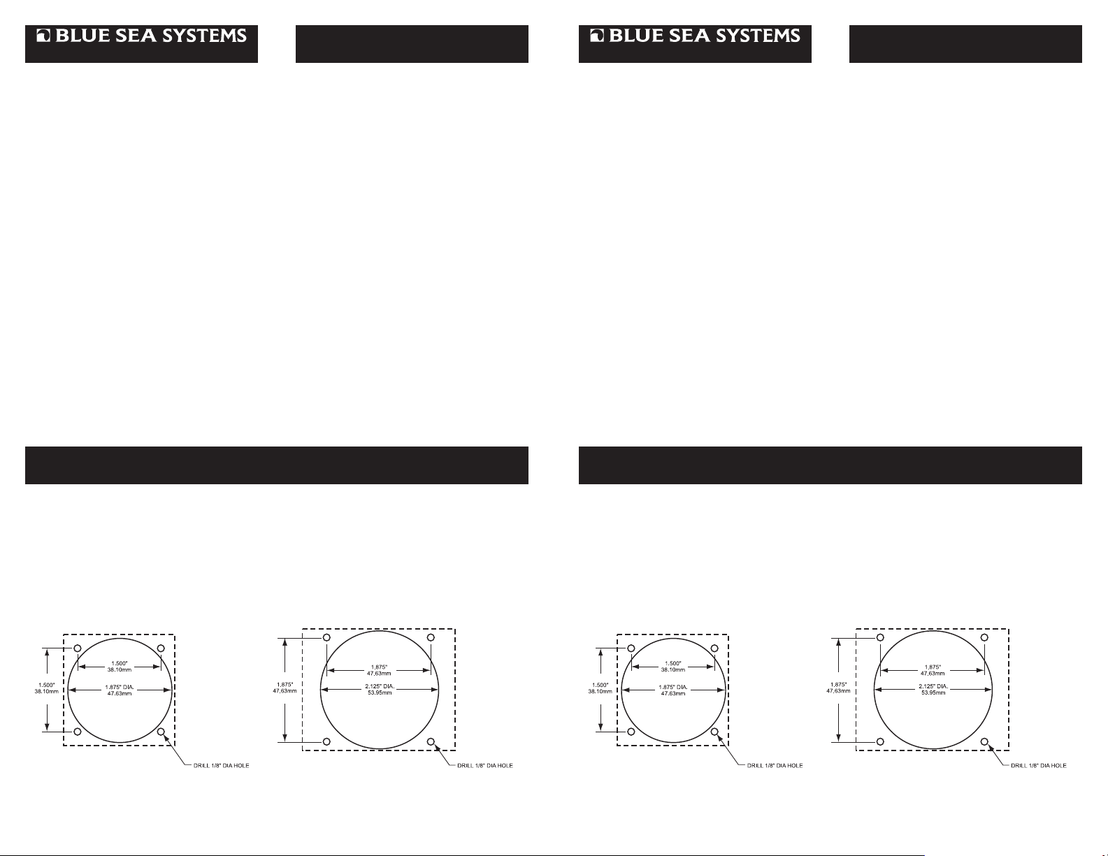
2. Select mounting location and cut opening
Select a mounting location which is protected from water on the meter front and back and is not
in an area where fl ammable vapors from propane, gasoline or lead acid batteries accumulate.
The meter is not ignition protected and may ignite such vapors. There are two mounting
methods for the meters, surface mount or panel mount.
Surface Mount: Drill fi ve clearance holes as shown below. The part number of the meter will
determine the size and location of the clearance holes. Use the nuts and washers supplied in the
accessory package to secure the four mounting studs to the mounting surface. This method will
work on mounting surfaces up to 5/8” thick.
PN 8246
Micro Meter
Panel Mount: For thicker mounting surfaces, the meter can be mounted into a 0.125” thick
panel. Blue Sea Systems offers meter mounting panels for our standard size meters only. Use
PN 8013 to mount a single meter or PN 8014 to mount two meters.
PN 8258 / PN 9630
Standard Meters
(
Installation (continued)
2. Select mounting location and cut opening
Select a mounting location which is protected from water on the meter front and back and is not
in an area where fl ammable vapors from propane, gasoline or lead acid batteries accumulate.
The meter is not ignition protected and may ignite such vapors. There are two mounting
methods for the meters, surface mount or panel mount.
Surface Mount: Drill fi ve clearance holes as shown below. The part number of the meter will
determine the size and location of the clearance holes. Use the nuts and washers supplied in the
accessory package to secure the four mounting studs to the mounting surface. This method will
work on mounting surfaces up to 5/8” thick.
PN 8246
Micro Meter
Panel Mount: For thicker mounting surfaces, the meter can be mounted into a 0.125” thick
panel. Blue Sea Systems offers meter mounting panels for our standard size meters only. Use
PN 8013 to mount a single meter or PN 8014 to mount two meters.
PN 8258 / PN 9630
Standard Meters
Page 2
(
Installation (continued)
(
Installation (continued)
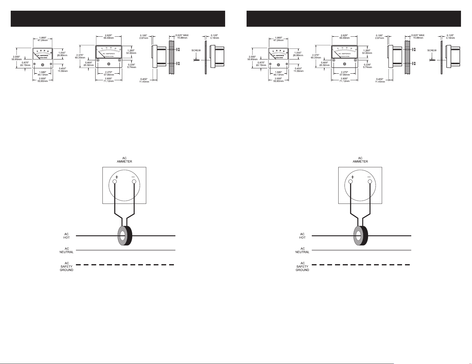
PN 8246 PN 8258 / PN 9630 Surface Mount Panel Mount
3. AC Meter Terminals
There are two terminals on the back of the meter marked “+” and “-”. On DC meters these
markings refer to positive and negative. On AC meters these markings can be disregarded.
Functionally it will not matter to which terminal the coil wires are connected.
4. Install Ammeter Coil
Route the AC hot lead to be measured through the center of the sensing coil. Connect the
sensing coil wires to the meter. Secure the sensing coil to the hot lead to prevent it from moving.
If needed, the sensing coil wires may be lengthened up to 50 feet (15.24m) using 16 AWG wire.
Wiring Diagram
AC Ammeters
PN 8258 / PN 9630
5. Calibration
The ammeter is calibrated at the factory and recalibration should never be necessary. However,
if adjustment does become necessary the needle may be reset to the zero mark.
In the center of the black area on the meter front is an adjustment screw. This screw activates a
small cam that defl ects the meter needle slightly to adjust the needle position.
Using a small screw driver, turn the screw no more than 90 degrees right or left, as necessary.
DO NOT ROTATE THE ADJUSTMENT SCREW THROUGH 360 DEGREES.
 Loading...