

Page 1
Marine Electrical Prod
ucts
Insulating Rear Cover for
360 Panel System
PN 1331 / PN 1341 / PN 1342 / PN 1343 / PN 4118
PN 1331 Insulating Rear Cover 1 Module
PN 1341 Insulating Rear Cover 2 Module
PN 1342 Insulating Rear Cover 3 Module
PN 1343 Insulating Rear Cover 4 Module
PN 4118 Adapter Kit
Features
• Isolates 360 panel AC components and circuits from DC system elements
• Meets ABYC safety requirements for panels with AC and DC loads
• Provides mechanical protection for panel backs protruding into lockers
• Interlocking companion pieces SIDE, TOP, and END can be stacked to
accommodate large AC components
• Cover breakouts allow wire access in any direction
Specications
Cover Material UL94 VO (Flame Retardant) Polycarbonate
Hardware 2 qty. 6-32 x ¾" Phillips-drive screws
4 qty. 8-32 x ½" Phillips-drive machine screws
with captive lock washers
Notes:
• Insulating Rear Covers cannot be installed over Push Button Reset-Only
Circuit Breaker modules.
• When installed over large source selector rotary switches, covers must be
stacked one on top of another (see Figure 5).
• When installed over meter modules, Systems Monitor 1800, and some
DC modules, an adapter kit is required (see Figure 3).
CAUTIONS
Verify that no DC and AC sources are connected to the vessel’s
electrical system before installing the Insulating Rear Cover.
If an inverter is installed on the vessel, its power leads must
be disconnected at the battery before the Insulating Rear Cover
is installed.
If an AC generator is installed on the vessel, it must be stopped and
rendered inoperable before installing the Insulating Rear Cover.
For AC/DC combination panels, ABYC compliance requires that
when the panel is open, there can be no access to energized AC
parts without the use of tools (ABYC E11.11.1.1). To comply, Insulating
Rear Covers should be installed over AC circuitry.
USCG compliance requires that DC circuitry, not protected by a fuse or
circuit breaker, must have a boot or an Insulating Rear Cover (Code of
Federal Regulation 183.445).
Guarantee
Blue Sea Systems stands behind its products for as long as you own them.
Find detailed information at www.bluesea.com/about.
For customer service, call 800-222-7617.
Blue Sea Systems Inc. Phone (360) 738-8230
425 Sequoia Drive Fax (360) 734-4195
Bellingham, WA 98226 USA E-mail conductor@bluesea.com
www.bluesea.com
990344130 Rev.000
Installation
1. To reduce the risk of electrical shock, disconnect all AC and DC power before installation. This includes inverters, generators, shore power attachments, and any
other device capable of supplying AC or DC power to the vessel’s circuits.
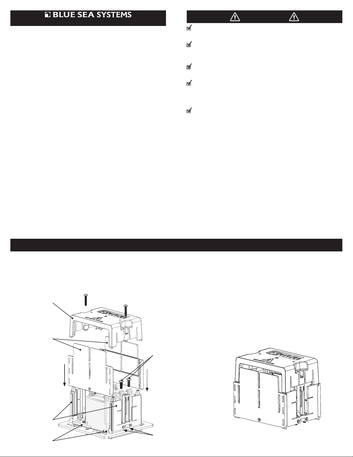
2. Place insulating cover(s) over module(s) to be insulated, aligning captive mounting screws in cover with threaded mounting holes in subframe.
3. Mark which breakouts are to be removed for wires to pass through cover. NOTE: Holes can be drilled in cover instead of removing breakouts.
4. Remove insulating cover, score along selected breakouts with a utility knife, and bend to remove breakouts (see Figure 6). IMPORTANT! For safety, slot or hole
size should be close to the diameter of the wire passing through the cover.
5. Replace insulating cover(s) over module(s) and fasten using captive mounting screws.
TOP
END
Captive Mounting
Screws
Slide END pieces onto
rails of SIDE components
SIDE
Subframe
Threaded mounting
holes in subframe
Insulating Rear Cover (assembled)
Figure 2Figure 1
Page 2
Installing Insulating Rear Cover Over Meter, Systems Monitor 1800, and Some DC Modules
NOTE: When installing insulating cover over meter, Systems Monitor 1800, and some DC modules, an adapter kit (PN 4118) is required.
1. Remove 4 Phillips at head bezel mounting screws from subframe.
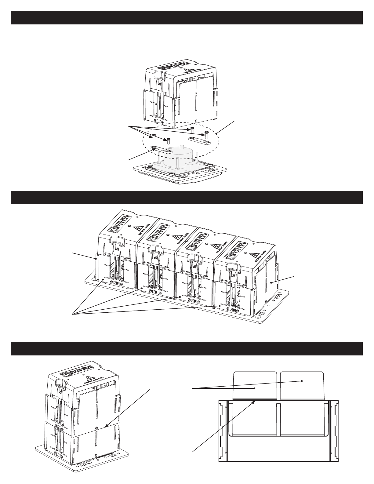
2. Using longer screws provided in Adapter Kit, attach adapters to subframe. Screws pass through adapters and subframe, and thread into bezel mounting holes.
3. Mount insulating cover as described in steps 2 through 5 above.
Bezel mounting screws to be
replaced with longer screws
used to attach adapters.
Install adapters with threaded
mounting holes toward the
outside edges of module.
Adapter Kit (PN 4118)
—Add adapters to install
Insulating Rear Cover over
meters, Systems Monitor
1800, and some DC modules.
Figure 3
Installing Column of Insulating Rear Covers
END
END
Modules
Figure 4
NOTE: When installing insulating covers in columns, use END piece only on both ends of column, not between individual covers.
Stacking Insulating Rear Covers for Tall Components
To stack, remove
breakouts from
END pieces on
base set.
Score here
before
breaking
Figure 6Figure 5
 Loading...