

Page 1
.
e
c
n
e
d
f
n
o
c
g
n
i
k
a
r
b
f
o
l
e
v
e
l
w
e
n
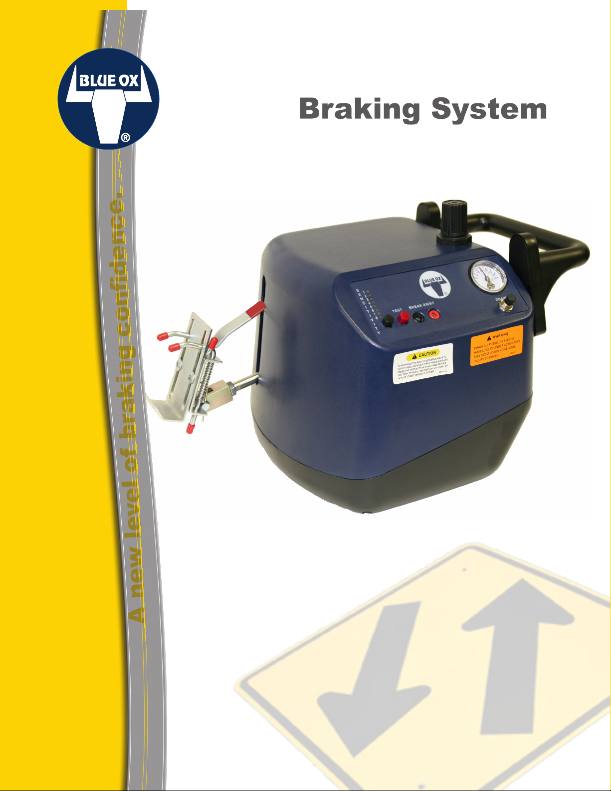
Apollo®
Braking System
Owner’s Manual
BX88179
(Apollo)
BX88193
(Luxor)
A
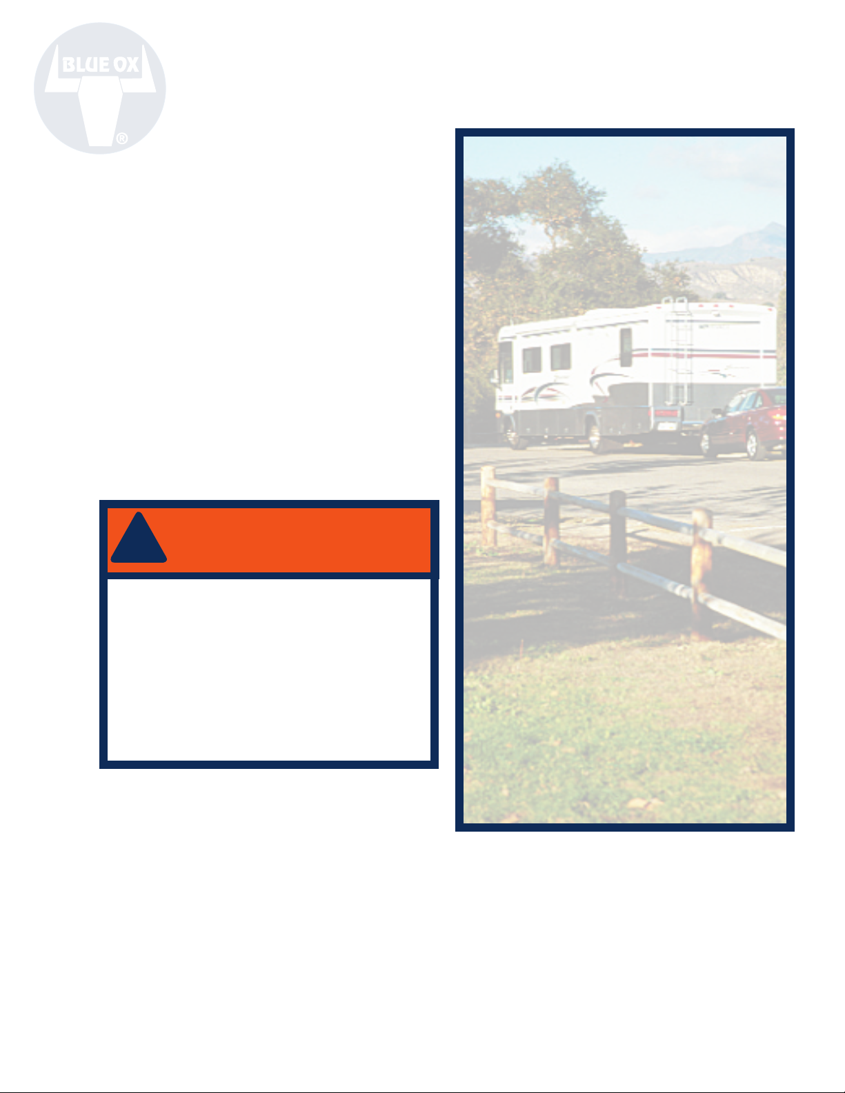
THANK YOU
for purchasing an Apollo braking system from
Blue Ox. We’ve organized this manual to make
your installation simple and as trouble-free
as possible. Insure it is read. Keep your sales
receipt and this manual in a safe place so that
both are available for future use if needed.
Page 2

Blue Ox®
Five-Year Limited Warranty
Automatic Equipment Manufacturing Company (“Automatic”) warrants to the original retail purchaser that each
product manufactured by Automatic shall be free from defect in material and workmanship under normal use and
service for a period of ve years from the date of delivery. In the case of equipment used for commercial or rental
purposes, such warranty period is limited to 30 days from the date of delivery to the original retail purchaser.
During said ve-year period (30 days in the case of equipment used for commercial or rental purposes), Automatic
will repair or replace any parts which (a) shall be returned to an authorized dealer, distributor, or the factory, with
transportation charges prepaid, and (b) aer examination by Automatic, are found to be defective. is limited
warranty will not cover, in any way, any alleged damages caused by incorrect or improper installation, improper
use, modication or neglect of product, or failure of the user to follow the guidelines contained in the instructional
material provided by Automatic.
REPAIR OR REPLACEMENT AS SET FORTH IN THIS LIMITED WARRANTY
IS THE SOLE EXCLUSIVE REMEDY OF THE PURCHASER. AUTOMATIC
SHALL NOT BE LIABLE FOR ANY INCIDENTAL OR CONSEQUENTIAL
DAMAGES FOR BREACH OF ANY EXPRESS OR IMPLIED WARRANTY ON
THIS PRODUCT. EXCEPT TO THE EXTENT PROHIBITED BY APPLICABLE
LAW, ANY IMPLIED WARRANTY OF MERCHANTABILITY OR FITNESS FOR
A PARTICULAR PURPOSE ON THIS PRODUCT IS LIMITED IN LENGTH TO
THE DURATION OF THIS WARRANTY.
Some states do NOT allow the exclusion or limitations of incidental or consequential damages, or allow
limitations on how long an implied warranty lasts, so the above limitations or exclusions may NOT apply
to you. is warranty gives you specic legal rights and you may also have other rights which vary from
state to state.
Automatic reserves the right to make changes or add improvements to its products at any time without
any obligation to make such changes to previously manufactured equipment.
IMPORTANT
Coverage and performance under the foregoing limited warranty is conditioned upon the original purchaser
completing and returning customer registration card to Automatic or registering via our web site at
www.blueox.us within ten days of delivery date and upon the original serial number being visible on the product
and unaltered. Automatic will not honor any warranty claims unless the warranty registration card is on le at
Automatic’s factory in Pender, Nebraska. Some states do NOT allow exclusions or limitations based on the return
of the registration card to the manufacturer, so the above limitations may NOT apply to you.
Blue Ox Division
Automatic Equipment Mfg. Co.
P.O. Box P
Pender, Nebraska 68047
www.blueox.us (402) 385-3051
I 292-2658 Date 09/06
Page 3
Product Information & Table of Contents
Equipment Information Record
Table of Contents
Date Purchased: _______________________
Purchased From: _______________________
Address: ______________________________
City:__________State: ___ Zip Code: ______
Phone Number of Dealership: ____________
Installed By: __________________________
Service #: _____________________________
Model #: ______________________________
Serial #: ______________________________
Notes: ________________________________
______________________________________
___________________________________________________________________________
___________________________________________________________________________
!
WARNING
-FOR YOUR SAFETY-
We recommend that this product be
installed by an authorized Blue Ox®
Professional Installer. Improper installation
and/or operation can create a hazard which
can cause serious injury, property damage
or death. Improper installation and/or
operation will void the warranty.
I
Warranty Information
II
Equipment Information Record
Table of Contents
24/7 Customer Care Information
Page 1
Description of Product
Page 2
Features and Benets
Page 3
Frequently Asked Questions
Page 4
Welcome to the Blue Ox Experience
Care and Maintenance
Page 5
Unpacking
Page 6
Parts List Itemization
Pages 7-10
Installation
Page 11
Operation
Pages 12
e Apollo® Illustrated
Pages 13-14
Breakaway System
Pages 15-16
Wireless Remote Indicator
Page 17-18
Troubleshooting
At Blue Ox® we pride ourselves in
oering exceptional customer service
to our valued customers.
If you have any questions, comments,
or concerns please feel free to contact
a member of our 24/7 Customer Care
Team by calling (402) 385-3051.
DEALERS AND DISTRIBUTORS:
PLEASE give the instructions to the customer so
they fully understand the setup, operation, and
safety precautions of this braking system.
Date 09/06 292-2658 II
Page 4

Apollo® Braking System
from Blue Ox®
Description of your product.
Just like all Blue Ox® towing products, the Apollo® braking system is built to
last. Be condent you’ll have superior performance for years to come. For added
comfort and security, Blue Ox stands behind the Apollo braking system with a
ve-year limited warranty on parts and labor.
Your RVs brakes are designed to stop your RV safely
and eectively. However, when adding the weight of
a towed vehicle, brakes can become overburdened
and fade or fail. is is why the Apollo braking
system from Blue Ox is such an important accessory
for RVs when towing a second vehicle.
It activates your towed vehicle’s brake pedal,
removing the entire weight of the vehicle from your
motor home’s stressed brakes. is means your RV
is better able to stop quickly and eciently.
Apollo makes advanced
braking simple. When you
apply pressure to your motor
home’s brakes, the Apollo
analyzes the braking in a
fraction of a second.
Install the Apollo in only a
few short steps. It requires
no electrical or mechanical
connections to the motor
home. Apollo contains
everything you need in one
convenient unit—including
an air pressure gauge and an air pressure regulator
that gets power from your 12-volt accessory outlet.
When it comes to braking, a
second can be the dierence
between a sure stop and an
accident. Be assured Apollo®
will apply the towed car’s
brakes - helping bring the
motorhome to a stop more
quickly and eciently.
the brake pedal engages—not simply when the
actuator arm extends from the brake case.
ese features mean Apollo delivers a more accurate
and reliable stop, with improved recognition of
unexpected developments. It does not aect your
towed vehicle’s Anti-Lock Braking System (ABS),
ride brakes down steep grades, or wear brakes more
than normal use.
With Apollo you get instinctive features adding
safety and convenience—like gauges and controls
that are conveniently located
with improved visibility and
access. Apollo meets SAE
governmental specication
and protects your towed
vehicle from a wiring or fuse
overload. Just plug it into the
12-volt accessory outlet.
Aer your towed vehicle’s
brakes are engaged, an
optional Wireless Remote
Indicator transmits a
signal back to your RV and
illuminates a dash-mounted light to let you know
the braking system is activated.
Transfer the Apollo easily between vehicles. It’s
small, lightweight and fully adjustable.
Apollo uses digital technology. is means when
you begin your stop, Apollo can engage your towed
vehicle’s brakes quickly - within 1/4 to 1/2 of a
second.
Apollo transmits an engagement signal only when
1 of 18 292-2658 Date 09/06
Apollo also contains a high-quality surge suppressor
to avoid unwanted braking on bumpy roads,
bridges, or railroad tracks. For ne adjustments,
Apollo oers sensitivity settings for your driving
style and environment. For breakaway situations,
Apollo provides an optional system that meets or
exceeds all requirements in the United States and
Canada.
Page 5

Features and Benets
is section explains the many dierent features and benets of your Apollo®.
• Convenient Design
Benet: e Apollo®’s compact size allows it
to be used in most applications. e unit sits
on the oor in front of the driver’s seat. It is
installed easily and does not void your towed
vehicle or motor home warranty. e Apollo is
lightweight. It weighs a mere 14 lbs. Transfer
the unit easily from one vehicle to another and
use it for several towed vehicles.
• Eight Sensitivity Settings
Benet: Get optimal braking performance by
choosing the setting that best ts the terrain
and your particular driving style.
• Constant Monitoring of G-Forces
Benet: e Apollo unit does this every 1/4
to 1/2 a second. It also provides continuous
application of the brakes during braking
application. Apollo takes 1/100 of a second to
start applying air to the brakes and only one
second until full pedal extension. e quicker
the system is activated, the faster the required
braking is applied. e Apollo utilizes solid
state sensing and activation. It has no moving
parts to inhibit proper braking activation.
• Satises Increasingly Strict Chassis
Manufacturer Braking Requirements
Benet: Reduces the risk of chassis warranty
issues regarding braking.
• Digital Normalization
Benet: Allows the unit to be normalized in
any application to compensate for unleveled
oorboards of the towed vehicle.
• Brake Bracket
Benet: e brake bracket is very durable—
increasing its lifetime value. e release handle
is easily released by a single hand operation.
Adjust it to t the size of your brake pedal
without diculty using a Phillips screwdriver.
• Brake Retracts Utilizing Air Pressure
Benet: Positive return. No spring. Complete
retraction.
• High-Quality Surge Suppressor
Benet: No unwanted braking on bumpy
roads, bridges, or railroad tracks.
• Large, Quick-Rell Air Tank
Benet: e large air tank ensures that the
compressor cycles less oen - increasing the life
expectancy of the system. e air tank takes a
minimal amount of time to rell because the
size of the tubing allows for a quicker response
with more air owing through the line.
• Corrosion Prevention
Benet: e Apollo has many components that
help prevent premature corrosion. e stainless
steel construction lasts longer. Air lters and
safety relief valves allow for long, troublefree operation. Micron air lters and a water
separator enhance the Apollo by protecting
it from system contamination and premature
failures. Air is taken in from above the tank,
ensuring the air is cleaner and drier—reducing
the chance of corrosion.
• Exhaust Air Outside of the Unit
Benet: Removing the air outside the unit
protects the circuits from water damage.
Accumulated moisture in the bottom of the
tank is purged—further preventing corrosion.
• Wireless Remote Indicator (Recommended)
Benet: e Wireless Remote Indicator
signals the system if the brake is actually being
applied in the towed vehicle. is eliminates
the possibility of false indicators that the brake
is engaged and provides easy monitoring of
braking engagement. e Wireless Remote
Indicator continues to transmit as long as the
brake pedal is depressed.
• Remote Indicator (Recommended) is
Activated from the Brake Light Switch of the
Towed Vehicle
Benet: is gives true indications of brake
activity in the towed vehicle.
• Breakaway System (Recommended)
Benet: Provides protection in the event your
towed vehicle becomes detached from your
motor home. e system immediately applies
the brakes of your towed vehicle and brings it
to a rapid stop. is system meets or exceeds all
Date 09/06 292-2658 2 of 18
Page 6

Frequently Asked Questions
Will the Apollo drain the battery of the towed
vehicle?
Answer: We recommend disconnecting the
Apollo and starting the vehicle each
night to recharge the battery. However,
depending on braking conditions, a typical
car battery can endure up to four days of
towing with the Apollo installed.
How does the Apollo know when to apply the
brakes?
Answer: e logic sensor recognizes and
reacts to changes in inertia.
How does the Apollo have enough power to
apply the brakes on a “dead pedal”?
Answer: e Apollo uses compressed air
to actuate the towed vehicle’s dead pedal.
Do you need a strap to pull the brake pedal
back?
Answer: No. Air pressure is used to pull
the brake pedal back.
Does the air pressure gauge show the amount
of PSI applied to the brake pedal?
Answer: No. It shows how much PSI is
applied to the Apollo’s cylinder in a
braking situation. e cylinder controls the
actuator arm pushing the brake pedal. So,
the higher the PSI, the more force that is
applied to the brake pedal.
Do brackets need to be mounted to the oor of
the vehicle?
Answer: No.
Can the outside case withstand the operating
conditions on a towed vehicle?
Answer: e Apollo’s outside case is
composed of Acrylonitrile Butadiene
Sytrene (ABS) plastic, the same plastic used to
make trim for the interior of automobiles. ABS
plastic is highly durable and withstands
extreme temperatures.
3 of 18 292-2658 Date 09/06
Do you have to wire anything to the towing
vehicle for the receiver of the wireless remote
indicator?
Answer: No. e receiver plugs into a
12-volt accessory receptacle.
What activates the LED of the wireless remote
indicator?
Answer: e light is activated when the
Apollo applies the brakes in the towed
vehicle. e wireless remote transmitter
senses actual current ow to brake lights
and transmits a digital signal to the receiver
in the towing vehicle. is illuminates the
receiver’s LED indicating that the brakes are
applied in the towed vehicle.
Will the transmitter of the wireless remote
indicator be able to transmit from underneath
the dash?
Answer: e transmitter will be able to
properly transmit from under the dash in
most cases. However, in some cases (i.e.,
diesel pushers), the transmitter may need
to be installed within the motorhomes line of
sight.
Does the wireless remote indicator require
cutting into the towed vehicle’s brake lines?
Answer: No. e wireless remote indicator
connects to the existing cold wire on the
brake pedal switch. is allows accurate
monitoring when the brakes are actually
applied (not when the unit is simply
activated). e Apollo is the only product
on the market that oers dierent
frequencies. is allows for traveling in
caravans or attending other group functions
without interference.
How does the Apollo recognize terrain?
Answer: e Apollo uses a built-in logic
sensor. e Apollo is digital and analyzes
Page 7

Welcome to the Blue Ox® Experience
Congratulations! You are now the proud owner of an Apollo® braking system.
Welcome to the Blue Ox® Family. e braking system that you have purchased combines quality
components with the latest in technology and style. We are condent that these design features will
provide you with the conveniences you expect during your travels. Aer you understand how to properly
and safely operate and care for your Apollo, expect years of trouble-free operation and service backed by
a ve-year limited warranty.
In this manual, you will nd installation instructions. Please read all of the technical documents,
warnings, cautions, tips, and notes in this manual before attempting to operate your Apollo for the rst
time. Improper installation, use or maintenance may result in malfunction causing personal injury or
property damage. Finally, don’t forget to ll out and return your warranty card. For future reference, your
serial number is located on the outside of the manual packaging and is also located on the bottom of your
Apollo unit.
WARNING
WARNING
!
!
Do NOT install the Apollo on
vehicles that have continuous
power assist brakes. Doing so will
cause severe tire damage.
Care & Maintenance
Care and Maintenance of your
Apollo Braking System
Your Apollo unit requires a minimal amount
of care and maintenance. If you do not feel
condent in your ability to perform the
occasional maintenance, consult your Blue Ox®
Dealer or Professional Installer, or see a Blue Ox
representative at a rally or race that you plan to
attend. e following will inform you of the areas
of your Apollo that will need periodic inspection
and/or care and maintenance.
Do NOT modify your Apollo® in
any way NOT authorized by Blue
Ox®, as it will void the warranty.
Care
Do NOT use any type of solvent or spray cleaner
on the Apollo braking system. e recommended
cleaning procedures for the Apollo are to wipe
down the exterior with a damp cloth. Wipe down
with a dry cloth.
Store in a clean, dry place.
Maintenance
It may be necessary to occasionally lubricate the
brake bracket with silicone spray.
- REMINDER -
Proper installation and
use of this product is the
sole responsibility of the
purchaser.
Date 09/06 292-2658 4 of 18
Page 8

Unpacking your Apollo® or Luxor™
Remove the Apollo® or Luxor and accessories from the shipping carton, see parts list and diagram below.
Make sure that you have the appropriate items shown below. If NOT, please contact a Blue Ox® Dealer
or Distributor, or call a member of the 24/7 Customer Care Team at (888)425-5382 to order replacement
parts.
Apollo and Luxor Braking Systems
e Apollo brake system is comprised of the Apollo (with brake
bracket assembly). e Luxor braking system is comprised of the
Apollo (with brake bracket assembly), wireless remote indicator, and
Breakaway system.
Apollo®
1
2
3
4
Wireless Remote Indicator (BX88180)
5
6
8
7
9
10
Breakaway System (BX88181)
11
16
15
1 Apollo assembly
2 Instructions
3 7/16” - 20 hex jam nut, ZP
4 Assy, brake bracket
5 *Transmitter
6 *Receiver
7 *Terminal bullet (female)
5 of 18 292-2658 Date 09/06
Contents:
8 *Terminal bullet (male)
9 *ScotchLok
10 *3/4” Velcro strips
11 *Breakaway switch with
Lanyard
12 *Replacement plug
13 *Banana clip (red)
14
13
14 *Banana clip (black)
15 *S Hook
16 *Cable Adjustor Plate
12
*Included only with the
Luxor system.
Page 9

Ref Qty. Part# Description
No.
1 1 62-3549 Apollo Assembly (BX88179)
2 1 292-6150 Instructions
3 1 202-0110 7/16”-20 Hex Jam Nut, ZP
4 1 62-3560 Assy, Brake Bracket
Parts List
Ref Qty. Part# Description
No.
Remote Alert System (included with Luxor)
5 1 62-3503 Transmitter
6 1 62-3504 Receiver
7 1 294-0853 Terminal Bullet (Female)
8 1 294-0854 Terminal Bullet (Male)
9 1 293-1419 ScotchLok
10 2 192-0028 3/4” Velcro Strips
11 1 293-1339 Breakaway Switch with Lanyard
12 1 62-3486 Replacement Plug
1
2
4
13 1 294-0839 Banana Clip Red
14 1 294-0840 Banana Clip Black
15 1 200-0149 S Hook
16 1 101-5822 Cable Adjustor Plate
3
Breakaway System (included with Luxor)
5
6
8
7
9
10
Tools
Required
Phillips Screwdriver
Wire Ties
Vise Grip
Rubber Grommet
WARNING
!
- USE ONLY GENUINE FACTORY
REPLACEMENT PARTS -
Do NOT substitute homemade or non-typical parts.
This may cause your brake to fail and result in injury
or death. If repair parts or components are needed,
you may order them through your nearest Blue Ox®
Dealer or Distributor, or call our 24/7 Customer Care
Team at (888) 425-5382.
11
16
15
14
13
Date 09/06 292-2658 6 of 18
12
Page 10

Installation
is section will explain how to install the Apollo®.
Note: Before installation, verify that a 12-
volt accessory receptacle is available and in
working order. Test with a cell phone charger
or other device. Be sure that the towed
vehicle’s ignition is in the “tow” position (key
turned forward, but engine NOT running)
when testing.
Step 2
1. Park the towed vehicle on a level surface.
2. Remove the protective cap from the
actuator arm.
3. read the hex jam nut onto the actuator
arm.
4. read the tting adapter of the brake
bracket onto the actuator arm and tighten.
5. With the towed vehicle’s engine o, press
the brake pedal four to ve times with your
foot. Doing this removes vacuum in the
Step 3
braking system.
6. Adjust the driver’s seat to the rear-most
position to allow for more working space.
Place the Apollo on the oorboard between
the seat and the brake pedal. Have the
actuator arm (extended) facing the brake
pedal.
Step 4
7 of 18 292-2658 Date 09/06
Page 11

Installation (con’t.)
7. Attach the brake bracket to the towed
vehicle’s brake pedal with the release handle
facing up. Position the brake bracket so that
its “feet” grab the top of the towed vehicle’s
brake pedal (step 7a). Note: You may need
to loosen the Phillips screws to adjust the
brake bracket to t the brake pedal (step 7b).
Step 7a
Step 8b
Step 8a
Back Support
Brace
Adjustment
Knob
Step 7b
8. Move the Apollo forward until the
actuator arm is fully retracted. Move the
seat forward until it contacts the Apollo.
Ensure the brake pedal is NOT depressed.
Note: If the seat does not reach the Apollo,
an extender may be needed. ese may be
obtained by contacting Blue Ox. e back
support brace should be 1/4 of the distance
up from the bottom of the seat (step 8a). If
it is not, slide the seat back so that you are
able to loosen the adjustment knob (step
8b). Adjust the back support brace up or
down accordingly (NOTE: e brace may
be ipped vertically if needed). e brace
should not slide under the seat or hit the
seat adjustor. If the vehicle is equipped with
an electric seat adjustor, use it to move the
seat height to the lowest position. When
the necessary adjustments have been made,
tighten the adjustment knob to secure the
back support brace. Slide the seat forward
until it contacts the Apollo (step 8c).
Step 8c
9. If the vehicle has a drive-line disconnect,
be certain it is out of the way to ensure the
Apollo does NOT engage it while towing.
10. Plug the Apollo into a 12-volt accessory
outlet and turn the power cord on. e
compressor lls the air tank. e power
light on the power cord should remain
illuminated with a solid green light.
Date 09/06 292-2658 8 of 18
Page 12

Installation (con’t.)
CAUTION
!
!
Do NOT exceed 90 lbs. PSI
DO NOT PRESS THE
TEST BUTTON YET!
11. With the vehicle parked on a level surface,
turn the ignition key to the ON or “towing”
position (key turned forward, but engine
NOT running). If the air compressor is
running, wait for it to stop.
Normalizing
1. While parked on level ground, power up Apollo. Wait for
compressor to fully charge.
2. Set the Sensitivity to 8.
3. Hold down the TEST button while pressing Sensitivity button
ve times.
4. Release the TEST button and the arm will actuate the
brake pedal.
5. Set the Sensitivity to your desired setting (see chart next
page). Normalizing is complete.
Step 12
Air Pressure
Regulator
Air Pressure
Gauge
12. Normalize your Apollo by following the
chart to the le. Normalizing your Apollo
re-levels the accelerometer when the
Apollo does NOT sit perfectly level on the
oorboard of the towed vehicle or if the
oorboard is not parallel with the towing
surface.
13. Adjust the application force if desired. e
application force is how hard your towed
vehicle will brake in tow. Adjust it with
the air pressure regulator on the top of the
Apollo. Your Apollo unit is factory pre-set
at 85 PSI. is is the recommended factory
pressure. You can adjust the air regulator
to enhance the sensitivity of your Apollo. If
desired, change the setting by liing the air
pressure regulator and turning it clockwise
to increase the pressure applied when
depressing the brake pedal (turn counter
clockwise to decrease pressure). Push the
regulator down to lock it into place.
9 of 18 292-2658 Date 09/06
Apollo’s come set from the factory at 85 psi.
Insure the Apollo is applying the proper amount
of pressure for your specic vehicle. Those
vehicles in which the Apollo is resting against a
soft surface may require more than 85 psi, but
not greater than 90 psi. Excessive force on the
braking system may cause tire damage.
WARNING
!
Page 13

Installation (con’t.)
Sensitivity
LED Lights
Button
Breakaway
Receptacles
Air Pressure Gauge
Drain ButtonTest ButtonSensitivity
Sensitivity Chart
Sensitivity Setting Braking Mode
1-2 Least Sensitive Braking
Note: e RV must be moving faster than 35
MPH for the Apollo to engage the brakes in
the towed vehicle.
14. Push the red TEST button on the Apollo
control panel four to ve times. e
actuator arm should extend and press the
brake pedal each time. Doing this insures
correct placement and removes the vacuum
stored in the brake vacuum reservoir of the
towed vehicle. Installation is complete.
Note: Resistance from the towed vehicle
may not always be felt in the RV. To monitor
the performance, we strongly recommend
using the BX88180 Wireless Remote
Indicator with the Apollo braking system. It
gives you the security of knowing when the
towed vehicles brakes are being applied.
3-6 Normal/Mid Braking
7-8 Most Sensitive Braking
Sensitivity Chart Information
e Sensitivity button (black button on the
le side of Apollo control panel) determines
how hard the brakes in the RV must be
applied before the Apollo engages the brakes
in the towed vehicle. e sensitivity is
increased (in increments of one to the
maximum level of eight) each time this
button is pressed. e higher the setting, the
easier the Apollo activates.
!
CAUTION
These settings are GENERAL
GUIDELINES ONLY and may
vary depending on conditions,
driver and/or the vehicles involved
in your particular towing situation.
Date 09/06 292-2658 10 of 18
Page 14

Disconnecting
is section will provide disconnecting information about the Apollo®.
Perform these steps each time you remove the Apollo.
1. Unplug the Apollo’s power cord from the 12-volt accessory outlet.
2. Push and hold the Drain button located on the control panel of the Apollo to release the air
pressure.
3. Adjust the driver’s seat back.
4. Unhook the brake bracket from the brake pedal. Unplug the Breakaway clips from the Apollo
control panel (if applicable).
5. Li the Apollo out of the vehicle.
!
CAUTION
Failure to drain your Apollo’s air
system and unplug the unit from
the car’s power source could
cause the Apollo to activate when
removing it from the vehicle,
resulting in injury to yourself and/
or others within the proximity.
11 of 18 292-2658 Date 09/06
Page 15

e Apollo® Illustrated
Sensitivity
Setting LEDs
Brake Bracket
Sensitivity
Button
Test
Button
Actuator Arm
Breakaway
Receptacles
Air Pressure Gauge
Drain Button
Air Pressure
Regulator
Back Support Brace
Adjustment
Knob
Drain Exhaust
Clockwise from Air Pressure Gauge:
Air Pressure Gauge
Displays the amount of air pressure in the system.
Air Pressure Regulator
Increases or decreases the amount of air pressure
in the cylinder. e amount of pressure (PSI) is
displayed on the air pressure gauge.
Back Support Brace
Enables you to carry your Apollo® unit. It also rests
against the bottom of the driver’s seat when the
Apollo® is installed.
12-Volt Power Cord
Plugs into the vehicle’s 12-volt power receptacle.
Provides power to the Apollo® from the towed
vehicle’s battery.
Adjustment Knob
Allows you to adjust the height of the back support
brace so that it sits correctly against the bottom of
the seat.
Drain Exhaust
Air exits the Apollo from this location when the
DRAIN button is used to release air pressure.
12-Volt
Power Cord
Drain Button
Pressing the DRAIN button releases air pressure
from the Apollo when not in use.
Breakaway Receptacles
e clips of the Breakaway system connect to these
receptacles.
Test Button
e TEST button activates the Apollo manually
to ensure it is working properly. Can also assist in
determining the appropriate Sensitivity setting.
Sensitivity Button
Adjusts the sensitivity. e higher the setting, the
less braking force required to activate the Apollo.
Sensitivity Setting LEDs
Displays the Sensitivity setting.
Brake Bracket
e brake bracket attaches to the towed vehicle’s
brake pedal.
Actuator Arm
When activated, extends to press the brake bracket
against the towed vehicle’s brake pedal.
Date 09/06 292-2658
Page 16

Breakaway System
Description of your product.
e Breakaway system automatically activates the Apollo® to apply the brakes on your towed vehicle in the event
the motorhome seperates from the towed vehicle. is type of emergency system is required by most states and
provinces.
Installation
is section will explain how to install the Breakaway (included with the Luxor™).
Ref Qty. Part# Description
No.
1 1 293-1339 Breakaway Switch with Lanyard
2 1 200-0149 S Hook
3 1 101-5822 Cable Adjustor Plate
4 1 294-0840 Banana Clip Black
5 1 294-0839 Banana Clip Red
6 1 62-3486 Replacement Plug
Breakaway System (included with Luxor)
1
3
2
4
5
6
1. Center and attach the Breakaway switch
to a solid part of the chassis (not to any
additionally installed item). Do not
overtighten. Ensure the switch is able to
pivot but does not pivot too freely.
2. Take the red and black wires leading
from the Breakaway switch and route
them through the underside of engine
compartment to the driver’s side rewall.
Secure the wires to non-moving items
through the engine compartment using
wire ties. Note: Keep the wires clear of sharp
edges.
3. Locate a rubber grommet on the rewall to
push the wires through and into the vehicle.
If one is not available, use a ¼” drill bit to
drill through the rewall. Place a rubber
grommet on the new hole to prevent the
wire from stripping later or grounding out.
Step 1
13 of 18 292-2658 Date 09/06
4. Strip ¼” of insulation from the end of the
wires. Insert the stripped wire end into
the color-coded banana clip (black wire to
black banana clip, red wire to red banana
clip) and tighten the set screw on pin.
Ensure the wire is securely tightened.
Page 17

Installation - Breakaway System (con’t.)
Breakaway
Sockets
Step 5
5. Plug banana clips into the color coded
Breakaway receptacles on the Apollo
control panel. Excess wire may be coiled
under the dash and secured with a wire tie
or stored under the oor mat or carpet.
6. Run the cable from the Breakaway switch
on the front of the towed car and hook to
a secure spot on the rear of the coach (not
the tow bar). Allow enough cable slack for
turning. A good indicator is if the cable can
be moved up and down a total distance of
six inches (i.e., three inches up, three inches
down) near the center of the cable.
Step 7a
Step 7b
Step 7c
7. read the cable through the included cable
adjustor plate as illustrated in the photos
and trim or tuck away the excess cable.
8. Slip the S Hook through the loop at the
end of the lanyard cable. Using a Vise grip,
pinch the S Hook to keep the cable inside
the S Hook.
9. Take the lanyard cable with S Hook and
hook it to the motorhome frame.
10. When not in use, unplug the lanyard
cable. Aer unplugging the lanyard cable,
simply insert the replacement plug into the
Breakaway switch. Use the replacement
plug to keep the Breakaway switch free of
debris when not in use.
Step 7d
Date 09/06 292-2658 14 of 18
Page 18

Wireless Remote Indicator
Description of your product.
With wireless technology, dangling and loose wires are a thing of the past. e wireless remote indicator transmits a
digital signal back to the towing vehicle and illuminates the receiver’s LED as soon as the towed vehicle’s brakes are
engaged - alerting you that the Apollo® braking system is activated.
Installation
is section explains how to install the Wireless Remote Indicator (included with the Luxor™).
1
2
Ref Qty. Part# Description
No.
Wireless Remote Indicator (included with Luxor)
1 1 62-3503 Transmitter
2 1 62-3504 Receiver
3 2 192-0028 3/4” Velcro Strips
4 1 293-1419 ScotchLock Connector
5 1 294-0854 Terminal Bullet (Male)
6 1 294-0853 Terminal Bullet (Female)
6
5
4
3
1. Remove the receiver from the package
(step 1).
2. Plug the receiver’s power cord into
the towing vehicle’s 12-volt accessory
receptacle.
3. Mount the receiver so that its LED faces the
towed vehicle and is also visible from the
RVs driver’s seat.
Step 1
Step 4
15 of 18 292-2658 Date 09/06
4. Remove the transmitter from the package
and ensure its serial number matches the
receiver’s serial number (step 4).
5. Use an electrical tester to determine the
cold side of the brake light wire. Attach the
transmitter wire to the cold brake light wire
in the towed vehicle using the ScotchLock
connector included.
Page 19

Installation - Wireless Remote Indicator
(con’t.)
Transmitter
Brake Signal Wire
Transmitter Wire
Male Terminal Bullet
Female Terminal Bullet
ScotchLock
Steps 6 & 7
6. Find the cold side of the brake signal wire
- under the dash and above the brake pedal.
It is usually located behind what looks like
a push button switch that releases when
the brake pedal is pressed – activating the
brake lights. Slip the slotted end of the
ScotchLock connector around the cold side
of the brake signal wire under the dash.
Insert the transmitter wire into the partially
plugged side of the ScotchLock connector.
7. Bring the transmitter wire out from under
the dash to a xed location (i.e. the glove
compartment or the side panel). Cut the
transmitter wire, crimp the female terminal
bullet onto the brake signal wire, and
crimp the male terminal bullet onto the
transmitter wire.
8. Plug the transmitter’s power cord into the
towed vehicle’s 12-volt accessory receptacle.
en, connect the two terminal bullets
together.
9. Attach Velcro to the back of the transmitter
and ax to a convenient location in the
towed vehicle. Mount with the front side of
the transmitter (labels are on the back side)
facing the rear of the towing vehicle.
Date 09/06 292-2658 16 of 18
Page 20

Troubleshooting
Issue: e Apollo® does not appear to power on.
Resolution: 1. Check fuse at the end of the power cord that plugs into the towed vehicle’s 12-volt
accessory receptacle. If the fuse is blown, only replace with a 15-amp slow blow fuse.
2. Plug Apollo® into another 12-volt accessory receptacle if available.
3. Check power at the 12-volt accessory receptacle with key in the “tow” position (key
turned forward but engine not running). If there is still no power, check the fuse in
the vehicle.
4. If you installed an additional 12-volt accessory receptacle, check its polarity.
Issue: e Apollo applies too much force to the brakes in the towed vehicle.
Resolution: 1. Insure towed vehicle’s engine is not running. Bleed o the vacuum assist by pressing
the brake pedal four to ve times with your foot.
2. Decrease the air pressure. Li the air pressure regulator and turn counter clockwise.
Push the air pressure regulator down to lock into place when nished.
Issue: e Apollo does not seem to be activating as I’m driving.
Resolution: 1. Increase the Apollo’s sensitivity level so that less braking force is required from the
towing vehicle to activate the Apollo.
2. e Apollo is a supplemental brake. It is NOT intended to activate unnecessarily
during mild braking applications. To insure that the Apollo’s sensitivity is set
properly, place it on the passenger’s side oorboard of the towed vehicle
(not connected to the brake pedal) and take a test drive. Adjust sensitivity to a
desired level aer observing activations during various braking scenarios.
Note : e towing vehicle must be moving faster than 35 MPH for the Apollo to
engage the brakes in the towed vehicle.
Issue: e Apollo does not activate aer initial installation.
Resolution: 1. Apollo needs to be ne tuned to your particular vehicle due to the many variations
of oorboards and interior designs. Ensure the seat is contacting the Apollo and that
the brake bracket is rmly attached to the brake pedal.
2. Normalize the Apollo.
17 of 18 292-2658 Date 09/06
Page 21

Troubleshooting (con’t.)
Issue: Apollo applies the brakes as soon as I plug it in.
Resolution: 1. If using the Breakaway system (included with the Luxor), ensure it is properly
connected and its clips are plugged into the Apollo. Bare wires can also activate the
Breakaway system, triggering the Apollo to engage the brakes.
2. Normalize the Apollo unit.
Issue: e compressor begins pumping and then continues to pump slowly.
Resolution: 1. ere may not be enough electrical current going to the Apollo. You may have
a weak battery or one that needs upgrading with a 12-volt battery direct kit (not
included). At a minimum, a 15-amp, 12-volt accessory receptacle is required to
operate the Apollo.
Issue: e towed vehicle’s tires are dragging.
Resolution: 1. is could be caused by the Apollo’s back support brace resting against a
seat that is very rm or by resting it against the metal brace underneath the seat.
Lower the PSI in increments of 10 (75 PSI, 65 PSI, etc.). is setting is displayed
on the air pressure gauge.
Issue: e Apollo’s Test button doesn’t work when the air compressor is running.
Resolution: 1. With the air compressor running, the battery may be dropping below the 12-volt
minimum required by the Apollo. Wait until the air compressor stops and then try
the Test button again.
Date 09/06 292-2658 18 of 18
Page 22

Don’t rely on overburdened brakes. Instead, rely on a
complete braking system from the company synonymous
with safe, reliable RVing. Blue Ox®.
To fnd the Blue Ox dealer nearest you,
visit www.blueox.us or call 888-425-5382.
Serial Number
Customer Service Commitment
Blue Ox® is focused on providing exemplary customer service, as observed in our mission
statement and guiding principles. In accordance with this objective, Blue Ox® is proud to provide
services such as repairs and general maintenance of Blue Ox® products at over 150 RV Rallies.
Look for our Destination America or Blue Ox® service crews at the next rally or race that you
attend. If you were not present, you will nd an informative, personalized note explaining any
services that may have been performed to your Blue Ox® products.
Blue Ox® also oers educational seminars at rallies and through our Parks and Resort teams. In
addition, Blue Ox® customers visiting our factory may take advantage of free use of the well-
equipped Blue Ox® RV park at no charge to you, our valued and appreciated customer.
© 2006 Blue Ox
Printed in the USA
292-2658
Blue Ox • One Mill Road, Industrial Park • Pender, Nebraska 68047
Phone: (402) 385-3051 • Fax: (402) 385-3360 • www.blueox.us
 Loading...