

Page 1
TM
®
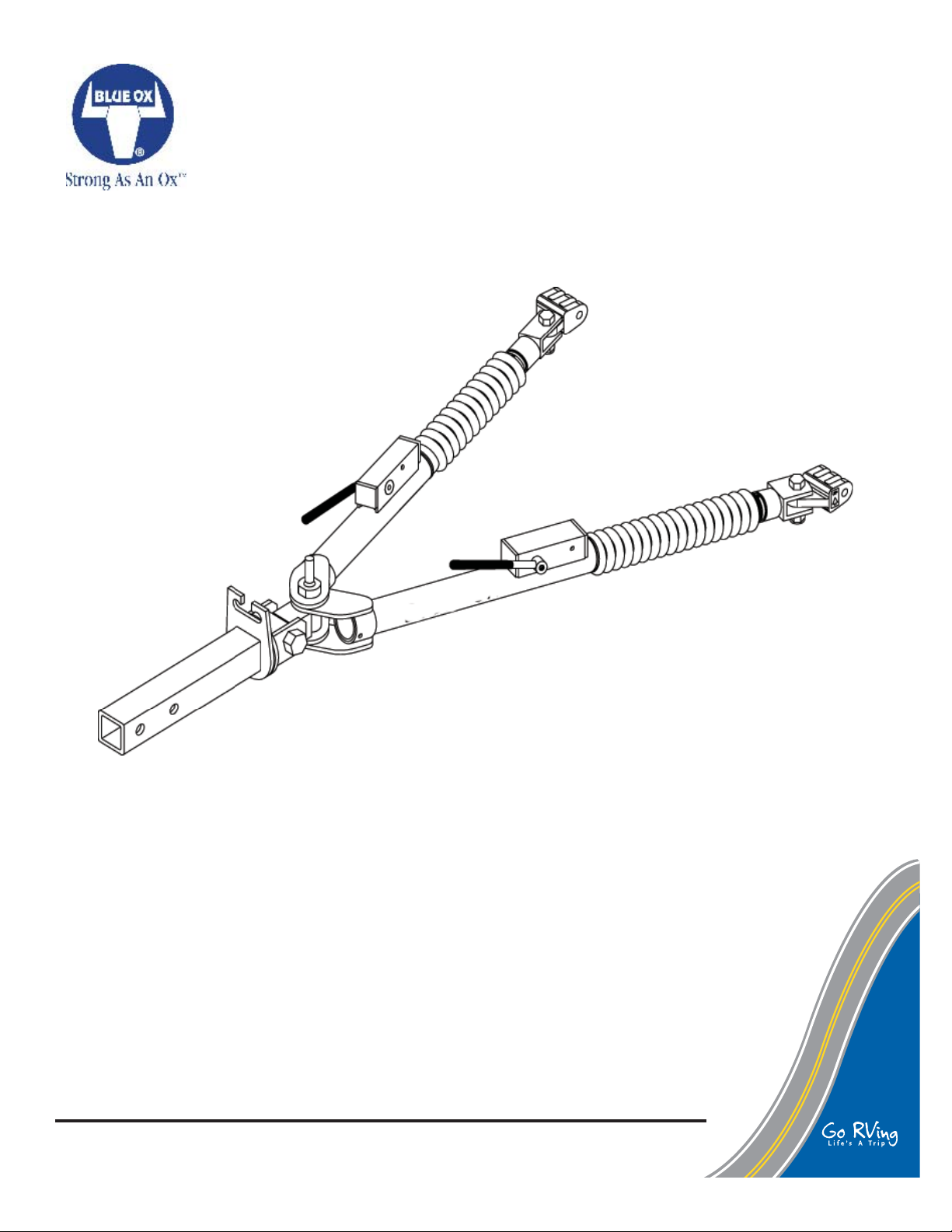
AVENTA
II
OPERATOR, PARTS, AND
INSTALLATION MANUAL
BX7335
AVENTA
Class IV (10,000 lb) 2 Inch Receiver
© 1996, 00, 06, 08, 10, 11 Blue Ox Division, Automatic Equipment Mfg. Co. • One Mill Road,
Industrial Park • Pender, Nebraska 68047 • Phone 402-385-3051 • Fax 402-385-3360 • www.
blueox.com
Page 1 of 9 292-2078 Rev. G 1/20/11
® II
Tow Bar
Page 2

TM
SAFETY
DO NOT INSTALL, OPERATE OR USE THIS EQUIPMENT UNTIL THE FOLLOWING
OPERATING AND SAFETY INSTRUCTIONS HAVE BEEN READ AND UNDERSTOOD.
This symbol is used to bring attention to safety precautions and instructions. When
you see this symbol, be alert and pay attention to all instructions. YOUR PER-
SONAL SAFETY IS INVOLVED.
1. Blue Ox Tow Bars should only be used with vehicles
that are towable or have been equipped to be towed.
2. Follow towing procedures in the vehicle owners
manual.
3. Tow with steering wheel in the unlocked position.
4. Be sure the front end of the towed vehicle is properly
aligned. Misaligned vehicles may cause poor tracking or abnormal wear on the tires.
5. The use of safety cables or chains are required
by law in most states of the United States as well
as Canadian territories and provinces. Follow
state or territory recommendations. Blue Ox
strongly recommends the use of safety cables
(BX88196, Class III or BX88197, Class IV) and
permanent safety cables (BX88207, Class III or
BX88208, Class IV) with all applications of towing. Please refer to their specifi c installation
instructions for more information.
6. Check clearance between vehicles in all turning
situations. Check the height difference in your towing
set up and make appropriate adjustments by follow-
ing the recommendations of the towbar instruction
manual.
7. Rear lighting is required on the towed car. Blue OX
offers lighting kits to cover all of your lighting needs.
Contact your Blue Ox representative for more information.
8. Prior to usage, inspect all towing equipment for
cracked welds, missing or worn parts and loose bolts.
9. Disconnect the towed vehicle from the towing vehicle
before backing up. Do Not Back Up while vehicles
are connected! Damage to both vehicles and the
towing system may occur. The towed vehicle may
jack knife causing abnormal stress to the tow bar, car
chassis, baseplate and/or pintle hitch of the towing
vehicle. These abnormal stresses may cause damage that may go undetected.
10. Avoid sharp turns and rough terrain. Check towing
set up after any emergency situation and/or periodically on a long trip.
11. Do not use the towed vehicle for storing luggage,
etc.; causing you to exceed the towing capacity
of the tow bar, baseplate, and its accessories.
SAFETY CABLE INSTALLATION
1. Utilizing the hooks, attach the cables to a solid
part of the chassis on the towed vehicle or the
convenience links of the baseplate. Verify the safety
snap clicks back against the hook in order to prevent
disconnection. (See Fig. 3)
2. Adjust slack if needed. Cables should not come
in contact with the ground, pintle coupler or the
locking handles; damage could occur! DO NOT USE
DAMAGED CABLES! Route cables away from the
locking handles. Safety cable contact with a locking
handle could cause the leg to become unlatched and
collapse, leading to major damage to one or both
vehicles and towing equipment. NOTE: DO NOT
WRAP SAFETY CABLES AROUND THE LEGS!
3. Verify the load capacity of cables or chains used that
meets the needs of the towing set up.
© 1996, 00, 06, 08, 10, 11 Blue Ox Division, Automatic Equipment Mfg. Co. • One Mill Road,
Industrial Park • Pender, Nebraska 68047 • Phone 402-385-3051 • Fax 402-385-3360 • www.
blueox.com
Page 2 of 9 292-2078 Rev. G 1/20/11
Page 3

TM
INSTALLATION
TOW BAR INSTALLATION (Towing Vehicle)
1. Slide the hitch connector into the receiver tube
of your towing vehicle hitch. Secure the receiver
pin provided into one of the two holes of the hitch
receiver. The inside hole of the receiver tube
is most commonly used. (Figure 1) Blue Ox
offers receiver and towbar lock sets (BX88101)
(BX88177) that help prevent theft. Contact Blue
Ox for more information.
2. Proceed with hooking up towed vehicle. (Page 3)
3. DEALER OR INSTALLER: BE CERTAIN USER
RECEIVES INSTRUCTION SHEETS.
NOTE: The confi guration of the rear of your
towing vehicle will determine how far you can
slide the hitch connector into the receiver tube.
Later, when the tow bar is folded, you may need
to change which set of holes are used in the
hitch connector or order a longer hitch connector.
CAUTION: As with any mechanical product,
care should be taken during installation and
operation, to prevent your fi ngers from being
pinched.
WARNING: Ensure that your
towing vehicle is of adequate size to
properly control your towed vehicle.
The weight and braking capacity
should be large enough to handle
both vehicles in an emergency
situation. Check your towing vehicle
manufacturers recommendations
for towing, hitch load, and
braking capacities. The hitch, ball,
motorhome chassis, and safety
cables (each individual cable) need to
be rated at a minimum for the weight
of the vehicle being towed.
CAUTION: It is important that the attachment
points at the center of the attachment tabs and
the center of the coach's hitch receiver should be
of equal distance. If a deviation must be present,
it should be no more than four (4) inches from the
tabs up to the hitch receiver. There should be no
deviation allowed for the hitch receiver tube to be
below the level of the attachment tabs. Refer to
Figure 2.
Figure 1
Figure 2
© 1996, 00, 06, 08, 10, 11 Blue Ox Division, Automatic Equipment Mfg. Co. • One Mill Road,
Industrial Park • Pender, Nebraska 68047 • Phone 402-385-3051 • Fax 402-385-3360 • www.
blueox.com
Page 3 of 9 292-2078 Rev. G 1/20/11
Page 4

TM
HOOKING UP / EXTENDING TOW BAR
HOOKING UP (Towed Vehicle)
1. Position the towing vehicle on a level
surface with a straight driveway ahead and
engage the parking brake. (Later, You will
be driving straight ahead to latch the legs
when extending the tow bar.) Position the
towed vehicle behind the towing vehicle in the
approximate towing position and engage the
parking brake of the towed vehicle.
2. Rotate the tow bar legs to the opposite side
of the stored position until the hold up bolt is
centered with the slot in the hitch connector.
Push the tow bar legs towards the towing
vehicle while raising them to allow the hold up
bolt to clear. If the hold up bolt does not align
with the gap, rotate the tow bar farther. Pull
the legs out away from the towing vehicle and
place them on the ground. NOTE: The hold
up bolt will pass through the gap in the hitch
connector when the legs are pulled out from
the towing vehicle. See Figure 4.
3. Partially extend one leg. The legs are held
in with an internal "soft" latch. Pulling out on
the leg will disengage this latch. Place the
triple lug between the attachment tabs on
the baseplate, and secure with the 1/2 pin.
See Figure 5. Be sure to place the 1/2" pin
is installed correctly through the attachment
tab with the nose towards middle of the
baseplate. See Figure 5 . Repeat for both
legs.
EXTENDING TOW BAR
Caution: It is possible to extend the tow
bar by driving away with the towing vehicle.
This can cause the towed vehicle to wander
from side to side and does not insure that
the legs will lock into position. We DO NOT
recommend towing any vehicle until
the operator has confi rmed that the leg
latches have been properly locked as
outlined in step 4.
4. On the towed vehicle disengage parking
brake and set up the transmission for towing,
see Safety section on Page 1 and unlock the
steering wheel. Pull forward with the towing
vehicle until one of the locking handles are
engaged and locked. (When locked they will
"pop" up)
NOTE: If only one locking handle is
locked, turn the top of the towed vehicle's
steering wheel towards the unlocked tow
bar leg approximately 1/2 to 3/4 turn, before
continuing forward. Pull the towing vehicle
Figure 4
forward one to two feet until the leg locks into
place. IMPORTANT: Check to insure both
legs are latched properly before towing. The
steering wheel on the towed vehicle must
be unlocked at all times while being towed.
Failure to do so will create hazardous driving
conditions.
5. Install safety cables or chains and lighting.
(See Safety Cable Installation - Page 1).
Figure 5
© 1996, 00, 06, 08, 10, 11 Blue Ox Division, Automatic Equipment Mfg. Co. • One Mill Road,
Industrial Park • Pender, Nebraska 68047 • Phone 402-385-3051 • Fax 402-385-3360 • www.
blueox.com
Page 4 of 9 292-2078 Rev. G 1/20/11
Page 5

TM
UNHOOKING TOW BAR / MAINTENANCE
Unhooking / Folding:
1. Park the towing vehicle with vehicle in tow,
in a straight line, on a fl at, level surface
to insure minimum pressure is exerted on
the tow bar legs. This will aid in the removal
of the 1/2 pins. Engage the towing vehicle
parking brake. Place the towed vehicle
either in park for automatic transmissions
or securely in fi rst gear for manual
transmissions. Unhook the lighting and safety
cables.
2. Disengage the leg latches by pushing down
on the locking handles. (Figure 5) Remove
the quick pins and 1/2 pins attaching the triple
lugs to the attachment tabs. You may need to
tap the 1/2 pins out if there is still pressure on
them. Compress both legs completely until
they lock in place.
NOTE: Each leg is equipped with a "soft"
latch inside the end. Push in on each leg until
they are held in detent by the soft latch.
NOTE: Place
the 1/2 pins
back into the
triple lugs and
secure with
the quick pin
assemblies to
avoid losing
either of
them.
3. With legs together, swing them up towards the
towing vehicle until the hold up bolt passes
through the gap in the hitch connector. (Figure
6) Rotate the legs down to either side until the
hold up bolt engages completely to the side of
the hitch connector slot.
Tow Bar Maintenance
Figure 6
2. Keep the tow bar covered when not in use, on
or off of the towing vehicle. This will cut down
on the dust and dirt build up on the legs and
latches of the tow bar. A BX8875 tow bar cover
is recommended.
3. Periodically clean the entire surface of the tow
bar with a mild soap and water solution. Wipe
dry with a clean cloth.
4. Check and replace any loose, worn or damaged
bolts, rubber boots or cap plugs.
5. Check for cracked welds and loose bolts on the
baseplate, towed vehicle (where baseplate is
bolted) and the hitch on the towing vehicle.
6. In normal straight line towing conditions, both
legs will be in tension. Due to the design of
the latch, both handles will feel loose. During
turning, braking or parking one or both of the
legs may be in compression. This will make
the handles feel stiff or tight. Due to parking on
slopes or the angle between the coach and the
car, the two locking mechanisms could be in
compression or tension or any combination of
the two. Having one lock in tension and one in
compression may give the operator the feeling
that one leg is locked and one is not, when in
fact whenever the legs are fully extended and
the springs are holding the latch handles up,
the legs are locked and ready to tow whether in
tension or compression.
Lubrication
1. Approximately once per year or if it is diffi cult to
move the legs in and out you should remove the
small cable ties holding the rubber boots on the
legs and slide the boots back. Wipe clean each
inside leg and apply a light coat of multipurpose
grease to insure smooth operation. Secure
each boot back in place with an 8 inch nylon
cable tie (available at most automotive and
hardware stores). See Fig 7.
1. This tow bar requires periodic maintenance.
It will be subjected to road dirt and weather
during use. The following tips will help
maintain the condition of your new tow bar.
Figure 7
© 1996, 00, 06, 08, 10, 11 Blue Ox Division, Automatic Equipment Mfg. Co. • One Mill Road,
Industrial Park • Pender, Nebraska 68047 • Phone 402-385-3051 • Fax 402-385-3360 • www.
blueox.com
Page 5 of 9 292-2078 Rev. G 1/20/11
Page 6

TM
REPLACEMENT PARTS
© 1996, 00, 06, 08, 10, 11 Blue Ox Division, Automatic Equipment Mfg. Co. • One Mill Road,
Industrial Park • Pender, Nebraska 68047 • Phone 402-385-3051 • Fax 402-385-3360 • www.
blueox.com
Page 6 of 9 292-2078 Rev. G 1/20/11
IMPORTANT: Use only genuine factory replacement parts on your Tow Bar. Do not substitute homemade
or nontypical parts. If a bolt is lost or in need of replacement, for your safety and the preservation of your
Tow Bar, be sure to use a replacement bolt of the same grade (Usually Grade 5).
Repair parts may be ordered through your nearest Blue Ox dealer or distributor.
Page 7

TM
REPLACEMENT PARTS
Parts List
Ref. Qty. Part Description
No. No.
1 3 202-0152 ..........3/4-16 Hex Nylon Insert Lock Nut
2 1 102-6374 ..................................... Threaded Insert
3 1 61-4789 ....................Hitch Connector, (Standard)
4 1 292-6176 ..........Decal, Measurement, Height Diff.
5 1 292-5860 ...............................ID. Sticker Aventa II
6 1 290-0348 .......Plastic Spacer, 3" O.D. x 1/16" Thk
7 1 100-1103 ................................................Cast Yoke
8 1 201-0632 ................3/4-16 x 3" Hex Bolt, Grade 5
9 2 203-0064 ....................................3/4" Flat Washer
10 1 201-0644 ..........3/4-16 x 3 1/4" Hex Bolt, Grade 5
11 1 100-1104 ....................................Swivel Lug, Black
12 6 290-0360 .Plastic Spacer, 1 1/2" O.D. x 1/16" Thk
13 1 229-0436 ..........................Machined Hold Up Bolt
14 2 290-0347 ...... Plastic Spacer, 2" O.D. x 1/16" Thk
15 1 61-4743 ...............Driver Side Round Outside Leg
16 1 61-4744 .......Passenger Side Round Outside Leg
17 2 290-0363 ...Plastic Spacer, 1 1/4" O.D. x 1/2" Thk
18 2 250-0169 ....................Grommet, 3/8" x 1" x 1/16"
19 2 229-0472 ....................................... Latch Retainer
20 2 62-3235 .......................................Inner Leg, Assy.
21 2 229-0386 ......................................Leg Stop, Steel
22 2 229-0032 ................Spring Pin, 3/16" x 1 1/4", ZP
23 2 207-0688 ..............................................Inside Leg
24 1 292-6236 ................... Sticker, Patent No., Towbar
25 2 292-1035 ............................Decal, Blue Ox, White
26 4 290-0332 .............Cap Plug, Black, 1 1/4" Square
27 2 201-0699 .........................1/4-20 x 1/2" Set Screw
28 1 292-1206 ...........Decal, Instructions (Not Shown)
29 1 292-1621 ....Decal, Cables Required (Not Shown)
30 2 220-0015 .............................Spring Pin, 3/16" x 2"
31 2 290-0394 ...............Locking Handle Spacer, Nylon
32 1 62-3750 ...................Latch Hndl Assy, Ald/A V2/Alx
33 2 250-0157 ...........Foam Grip, 3/8" X 3 5/8" X 5/64"
34 2 207-0881 ...................Locking Handle, SS, W/Slot
35 2 299-0234 .....Swivel Locking Handle, Steel Plated
36 2 201-0504 ....1/4-20 x 1/4" Set Screw, Knurled, ZP
37 2 229-0387 ......................Locking Handle, Bolt, SS.
38 2 290-0377 ..Plastic Wshr, .765 ID. x 1" OD. x 1/16"
39 2 220-0033 .........................Spring Pin, 1/4" x 1 3/8"
40 2 222-0068 ..........................Spring, Locking Handle
41 2 290-0364 ...........................9 Inch Nylon Cable Tie
42 2 250-0156 ...........................................Rubber Boot
43 2 290-0275 ...........................8 Inch Nylon Cable Tie
44 2 61-5484 ................................Weldment, Leg Pivot
45 2 220-0032 ..................... 3/16" x 1 1/4" Roll Pin, ZP
46 2 201-0645 .................1/2-13 x 2 Hex Bolt, Grade 5
47 4 290-0381 ... Nylon Washer,.051 x .523 x 1.38 OD.
48 2 202-0143 .....................1/2-13 Essna Jam Nut, ZP
49 2 100-1176 ..................................... Offset Triple Lug
Ref. Qty. Part Description
No. No.
50 2 292-2660 ..............................................Decal Up Arrow
51 2 229-0674 ................Pin, 1/2 X 2 5/8 Eff, W/Spring Lock
52 1 200-1483 ................................Pin, 5/8" x 3 Eff., W/ Clip
Replacement Leg Assemblies
53 1 84-0053 ............................ DS Complete Leg Assembly
54 1 84-0054 .............................PS Complete Leg Assembly
Replacement Hitch Connector Assemblies
(Completely Assembled)
55 - 84-0051 ...........Hitch Assy, Short (Complete, Optional)*
56 1 61-4716 ...................Weldment, Hitch Connector, Short
57 - 84-0052 ....Hitch Assy, Standard (Complete, Standard)*
58 - 84-0047 ........ Hitch Assy, Long (Complete, Optional)*
59 1 61-4790 ................... Weldment, Hitch Connector, Long
Replacement Hitch Connector Assemblies
(2 1/2" Receiver for Aladdin and Aventa II)
(Completely Assembled)
60 1 102-6692 ...................Nut, 2.5 Receiver, 3/4-16 Thread
61 - 84-0107 ..Hitch Assy, 2.5 Rcvr, Short (Complete, Opt.)*
62 1 61-6147 ..Wdlm't, Hitch Conn., 2.5 Rcvr. Short, Av2/Ald
63 - 84-0108 Hitch Assy,2.5 Rcvr,Standard (Complete,Opt.)*
64 1 61-6148 Wldm't,Hitch Conn.,2.5 Rcvr.Standard,Av2/Ald
65 - 84-0109 Hitch Assy,2.5 Rcvr, Long (Complete,
Opt.)*
66 1 61-6149 ...Wldm't, Hitch Conn.,2.5 Rcvr. Long, Av2/Ald
© 1996, 00, 06, 08, 10, 11 Blue Ox Division, Automatic Equipment Mfg. Co. • One Mill Road,
Industrial Park • Pender, Nebraska 68047 • Phone 402-385-3051 • Fax 402-385-3360 • www.
blueox.com
Page 7 of 9 292-2078 Rev. G 1/20/11
Page 8

TM
REPLACEMENT PARTS
© 1996, 00, 06, 08, 10, 11 Blue Ox Division, Automatic Equipment Mfg. Co. • One Mill Road,
Industrial Park • Pender, Nebraska 68047 • Phone 402-385-3051 • Fax 402-385-3360 • www.
blueox.com
Page 8 of 9 292-2078 Rev. G 1/20/11
Page 9

TM
QUICK REFERENCE GUIDE
HOOKING UP & EXTENDING FOR TOWING
1. Align vehicles in towing position with straight driveway
ahead and parking brakes locked.
2. Rotate legs up to unfold tow bar. Partially extend legs,
pin double pivot lug between baseplate attachment
tabs.
3. Drive towing vehicle forward until both legs are locked.
(Locking Handles Up)
4. Install safety cables and towed vehicle lighting.
5. Detailed instructions appear on page 3.
TO BE VALID, THE WARRANTY CARD MUST BE
COMPLETED IN ITS ENTIRETY BY AN AUTHORIZED
DISTRIBUTOR OR DEALER AND SENT TO AUTOMATIC
EQUIPMENT MFG. CO., PENDER, NEBRASKA. FAILURE
TO DO SO WILL V OID THE WARRANTY.
Repair parts may be ordered through your nearest
Automatic dealer or distributor.
UNHOOKING & FOLDING FOR STORAGE
1. Park vehicles in a straight line on level surface. Apply
towing vehicle parking brake. Place towed vehicle in
park or 1st gear for manual transmissions.
2. Remove safety cables and towed vehicle lighting.
3. Disengage locking handles, remove quick pins and
connector pins and replace to prevent loss.
4. Compress and place legs together, fold towards towing
vehicle and rotate down to engage hold up bolt.
5. Detailed instructions appear on page 4.
Product Safety Policy Statement
It is, and shall continue to be, a primary objective of Automatic Equipment Manufacturing Company to provide customers with safe and reliable products. Automatic will, and has,
established safety procedures in product design, manufacture, promotion and sales; and will
coordinate efforts to promote customer safety to the greatest extent possible. Each department
has primary responsibility for the promotion of safety under the guidelines of the Product Safety
Committee.
WARNING: Ensure that your towing vehicle is of adequate size to properly
control your towed vehicle. The weight and braking capacity should be large enough
to handle both vehicles in an emergency situation. Check your towing vehicle
manufacturers recommendations for towing, hitch load, and braking capacities. The
hitch, ball, motorhome chassis, and safety cables (each individual cable) need to be
rated at a minimum for the weight of the vehicle being towed.
© 1996, 00, 06, 08, 10, 11 Blue Ox Division, Automatic Equipment Mfg. Co. • One Mill Road,
Industrial Park • Pender, Nebraska 68047 • Phone 402-385-3051 • Fax 402-385-3360 • www.
blueox.com
Page 9 of 9 292-2078 Rev. G 1/20/11
 Loading...