

Page 1
AVENTAAVENTA
AVENTA
AVENTAAVENTA
TM
OPERATOR, PARTS AND
INSTALLATION MANUAL
BX7330
AVENTAAVENTA
AVENTA
AVENTAAVENTA
TOWING PRODUCTS DIVISION
TM
Tow Bar
Page 2
SAFETY
DO NOT INSTALL, OPERATE OR USE THIS EQUIPMENT UNTIL THE FOLLOWING
OPERATING AND SAFETY INSTRUCTIONS HAVE BEEN READ AND UNDERSTOOD.
This symbol is used to bring attention to safety precautions and instructions. When you
see this symbol, be alert and pay attention to all instructions. YOUR PERSONAL
SAFETY IS INVOLVED.
1. Blue Ox Tow Bars are designed to tow
manual transmission cars or automatics
equipped with a transmission pump, drive
shaft disconnect or half shaft disconnect.
2. The transmission is in neutral when towing.
3. Unlock the steering wheel to allow the front
wheels of the towed vehicle to “track”.
4. Be sure the front end of the towed vehicle is
properly aligned.
5. The use of safety cables or chains is RE-
QUIRED BY LAW. Model BX8805 (5ft) or
BX8806 (6ft) cables are recommended. The
shorter BX8805 is normally best.
6. Check clearance between vehicles in a
turning situation.
7. Most States require rear lighting on the towed
car. A BX8811 Wiring Kit or BX8834 Light
Bar is recommended.
8. Prior to a towing trip, check to be sure all the
towing accessories and attachment points
are secure. Check for cracked welds and
loose bolts. This is important on all occasions, but particularly on a new installation,
when they should be checked just prior to
initial towing and again after 100-200 miles of
towing.
9.
Do Not Back Up
when towing. Backing up
may damage the Tow Bar Assembly, towing
vehicle's chassis or towed vehicle's chassis.
10. Avoid sharp turns and rough terrain. Check
installation after any unusual event and
periodically on a long trip.
11. Do not use the Towed Vehicle for storing
luggage, etc.; you may exceed the towing
capacity of the Tow Bar.
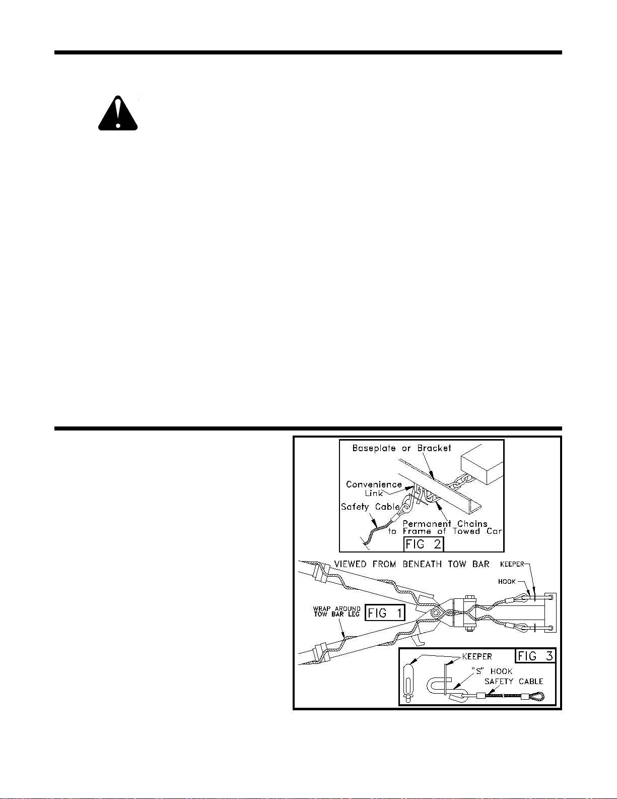
SAFETY CABLE INSTALLATION
1. Using the cable hooks, attach the cables to a
solid part of the chassis of the towed vehicle or to
the baseplate convenience links on unibody cars.
Slip the end of the S-hook through the neoprene
keeper to prevent it from unhooking. (See Fig. 3)
NOTE: It is best to have permanent chains that
connect the convenience links to the frame of the
car. (See Fig. 2)
2. Wrap each cable once or twice around their
respective tow bar leg and cross them under the
receiver area. (See Fig. 1)
3. Using the S-hooks, attach the opposite ends of
the cables to a solid part of the chassis of the
towing vehicle if at all possible. Slip the end of
the S-hook through the neoprene keeper to
prevent it from unhooking
(See Fig. 3)
4. Adjust slack so that the cables cannot touch the
ground or become caught beneath the receiver.
If either of these things happen, the cables may
become damaged and ineffective. DO NOT USE
DAMAGED CABLES!
5. If BX8805 or BX8806 cables are not used, be sure
EACH cable or chain used has at least the load
rating of the tow bar (5000 lbs.).
292-1661 2/96 1 of 6
Page 3
TOW BAR INSTALLATION
CAUTION: As with any mechanical product, care
should be taken during installation and operation, to
prevent your fingers from being pinched.
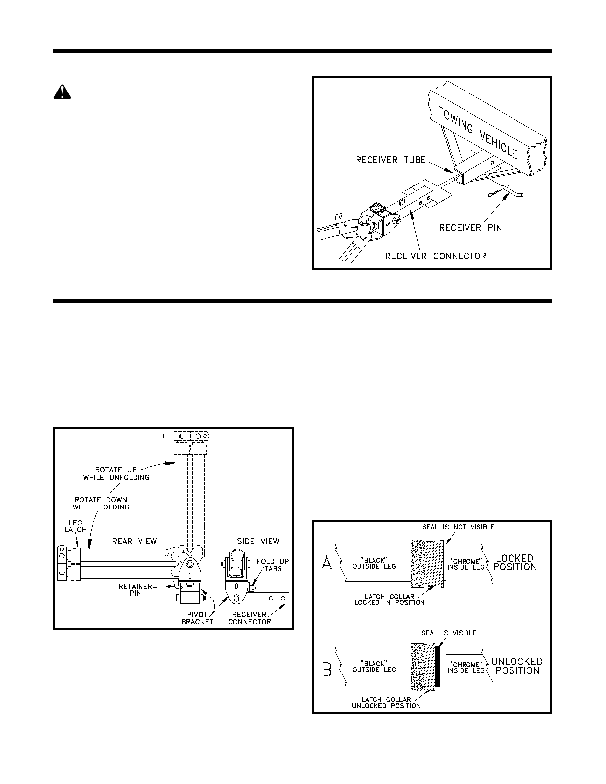
1. Slide the receiver connector into the receiver tube
of your towing vehicle hitch. Secure it with the
receiver pin provided. (Figure 1)
NOTE: The configuration of the rear of your
towing vehicle will determine how far you can slide
it into the receiver. Later, when the tow bar is
folded, you may need to change which set of holes
is used in the receiver connector.
2. Proceed with hooking up towed vehicle.
3. DEALER OR INSTALLER: BE CERTAIN USER
RECEIVES INSTRUCTION SHEETS.
INSTALLATION / HOOKING UP
Figure 1
HOOKING UP (Towed Vehicle)
1. Position the towing vehicle on a level surface with
approximately 100 ft. to 200 ft. of straight driveway
ahead and engage the parking brake.
will be driving straight ahead to latch the legs
when extending the tow bar.)
vehicle behind the towing vehicle in the
approximate towing position and engage the
parking brake of the towed vehicle.
Position the towed
(Later, You
NOTE: Replace wire lock pin into fold up tabs and
lock in place to avoid losing pin.
3. Unlock one of the leg latches and partially extend
the leg.
NOTE: Leg latches are unlocked by sliding the
collar back to expose the red rubber seal under
the collar. (Figure 3)
4. Refer to figure 4 on page 3. Place the baseplate
connector between the baseplate attachment tabs
on the towed vehicle and secure with the
connector pin tethered to the leg. Be sure to place
the quick pin, also tethered, through the hole in the
connector pin to lock it in place. The quick pin
only locks when the ring is rotated towards the
nose of the quick pin. Repeat for both legs.
Figure 2
2. Face the folded tow bar on the rear of the towing
vehicle. (Figure 2) Remove the wire lock pin from
the tow bar fold up tabs. Unfold the tow bar by
raising the tow bar legs until the retainer pin clears
the slot in the pivot bracket. Pull the legs out
away from the towing vehicle and place them on
the ground.
Figure 3
292-1661 2/96 2 of 6
Page 4

EXTENDING TOW BAR / UNHOOKING / FOLDING
EXTENDING TOW BAR
Caution: It is possible to extend the tow bar by
driving away with the towing vehicle. As you drive
away, the towed vehicle will wander around until,
eventually, both sides may lock. Even though
they may lock this way, we DO NOT recommend
towing any vehicle until the operator has
confirmed that the leg latches have been
properly locked as outlined below.
1. On the towed vehicle; disengage parking brake,
set up the transmission for towing, (See SAFETY
section - Page 1, Item 1) and unlock the steering
wheel. Drive the towing vehicle straight forward
approximately 50 ft. to 100 ft. or until both leg
latches lock into position. The latches are locked
when the red rubber seal is not exposed.
NOTE: If only one leg latch locks, turn the top of
the towed vehicle's steering wheel towards the
unlocked side, approximately 1/2 to 3/4 turn, and
continue forward until the latch locks.
insure both legs are latched properly before
towing. IMPORTANT: The steering wheel on the
towed vehicle must be unlocked at all times while
being towed. Failure to do so will create
hazardous driving conditions.
2. Install safety cables or chains and lighting. (See
safety cable installation - Page1).
Check to
Figure 4
UNHOOKING / FOLDING
1. Park the towing vehicle with vehicle in tow, in a
straight line, on a flat, level surface to insure
minimum pressure is exerted on the tow bar legs.
This will aid in the removal of the connector pins.
Engage the towing vehicle parking brake. Place
the towed vehicle either in park for automatic
transmissions or securely in first gear for manual
transmissions. Unhook the lighting and safety
cables.
2. Unlock the leg latches by sliding the collar back to
expose the red rubber seal under the collar.
(Figure 3) Remove the quick pins and connector
pins attaching the tow bar legs to the baseplate
attachment tabs. (Figure 4) You may need to tap
the connector pins out if there is still pressure on
them. Compress both legs completely, until they
lock in place. (Latch is locked when the red rubber
seal is not exposed)
3. With the legs together, swing them up towards the
towing vehicle until the single fold up tab on the
receiver connector fits between the double fold up
tabs on the pivot bracket. Slide the wire lock pin
through the fold up tabs and lock in place. Rotate
the legs down to the side until the retainer pin
engages in the slot in the pivot bracket. (Figure 2)
292-1661 2/96 3 of 6
Page 5

MAINTENANCE
MAINTENANCE
1. This tow bar requires periodic maintenance. It will
be subjected to road dirt and weather during use.
The following tips will help maintain the condition
of your new tow bar.
2. Keep the tow bar covered when not in use, on or
off of the towing vehicle. This will cut down on the
dust and dirt build up on the inside legs and
latches of the tow bar. A BX8865 AVENTATM tow
bar cover is recommended.
3. After each trip, after 5000 miles of towing or
before long periods of storage, lubricate the leg
latches with silicone lubricant or a similar product.
Wipe dry with a clean cloth.
LATCH DISASSEMBLY
If your latches become "sticky" or hard to latch
they may require disassembly for cleaning. The best
way to disassemble your tow bar for cleaning is to take
apart both latches in the order specified below, clean,
then reassemble as outlined.
1. Unbolt the baseplate
connectors from the
inside legs of the tow
bar. Place the tow bar
legs in the folded
position. (See
Unhooking / Folding
Section) Release the
leg latches and remove
the inside legs.
REASSEMBLING THE TOW BAR
1. Replace the washer, spring, and latch collar and
secure with the snap ring. NOTE: Be sure to
install the spring with the narrow end towards the
washer.
2 Slide the inside leg back through the outside leg.
Hold the outside leg vertical and raise the inside
leg until the holes are just above the end of it.
Insert a ball bearing into one of the holes and hold
it in place with the inside leg by keeping slight
pressure upwards against the ball bearing. While
keeping slight pressure on the ball bearing, insert
the rest of the ball bearings.
3. Once all ball bearings are in their holes, release
the latch collar and allow the inside leg to go on
through the latch assembly. Lock the ball
bearings into the groove in the inside leg. Repeat
for other leg latch. Reattach the baseplate
connectors and hardware previously removed.
NOTE: Care should be
taken not to lose the 6
ball bearings that will
come out as each leg is
removed.
2. Remove the red dust
seal and the snap ring
that holds the latch
together. Remove the
latch collar, spring, and
latch washer.
CLEANING
1. Clean all of the parts removed with a grease
cutting solvent. Clean the chrome inside legs,
cross pivot brace and all outside legs and collars.
NOTE: Be sure to clean the inside of the collars
and legs, including brushing out the ball bearing
holes.
Figure 5
LUBRICATION
1. Once the tow bar has been cleaned and
reassembled, lubricate the leg latches with silicon
lubricant and insure that both latches operate
smoothly.
292-1661 2/96 4 of 6
Page 6

REPLACEMENT PARTS
IMPORTANT: Use only genuine factory replacement parts on your Tow Bar. Do not substitute home-
made or nontypical parts. If a bolt is lost or in need of replacement, for your safety and the preservation of your Tow Bar, be sure to use a replacement bolt of the same grade (Usually Grade 5).
Repair parts may be ordered through your nearest Automatic dealer or distributor.
292-1661 2/96 5 of 6
Page 7

REPLACEMENT PARTS
Parts List
Ref. No. Qty. Part No. Description
1** 1 61-4439........................................................................................Outside Leg
2 2 61-4446......................................................................... Baseplate Connector
3 1 61-4448...................................................................... Plate Washer, 3/4 Hole
4* 1 61-4727........................................................................... Receiver Connector
5 1 61-4728...................................................................... Pivot Bracket w/ Brace
6 1 61-4729....................................................................Pivot Bracket w/ Spacer
7** 1 61-4730........................................................... Outside Leg with Retainer Pin
8 2 62-3213........................................................................... Quick Pin Assembly
9 2 62-3214.................................................. Baseplate Connector Pin Assembly
10 1 107-1836...................Leg Spacer Tube, 1 OD x 11 Ga. Wall x 1 13/16 Long
11 1 200-1483.....................................................................Pin, 5/8 x 3 Eff. w/ Clip
12 2 201-0011........................................... 1/2-13 x 1 1/4 Hex Head Bolt, Grade 5
13 2 201-0615........................................... 3/4-16 x 4 1/2 Hex Head Bolt, Grade 5
14 2 201-0616........................................... 1/2-20 x 2 3/4 Hex Head Bolt, Grade 5
15 1 201-0622........................................... 3/4-16 x 2 1/2 Hex Head Bolt, Grade 5
16 2 202-0150.......................................................1/2-20 Lock Nut w/ Nylon Insert
17 3 202-0152....................................... 3/4-16 Hex Jam Lock Nut w/ Nylon Insert
18 2 203-0012.............................................................................. 1/2 Lock Washer
19 2 203-0127......................................................................... Safety Stop Washer
20 12 209-0139................................................................................3/8 Ball Bearing
21 2 222-0062..................................................................................... Latch Spring
22 2 229-0283......................................................................................... Snap Ring
23 1 229-0380...................................................................... Wire Lock Pin, 1/4 x 2
24 2 250-0167............................................................... Outer Seal, Tow Bar Latch
25 4 290-0266.........................................................Nylon Washer, 1 OD x .518 ID
26 2 290-0314...................................................................................... Latch Collar
27 2 290-0315............................................................................. Latch Back Cover
28** 2 290-0316..........................................................................................Dust Seal
29 2 290-0345............................................................................... Plastic Cap Plug
30* 2 290-0346............................................................................Plastic Pivot Insert
31 4 290-0347...................................................... Plastic Spacer, 13/16 ID x 2 OD
32 2 290-0348...................................................... Plastic Spacer, 13/16 ID x 3 OD
33 2 292-1035.................................................................................. Blue Ox Decal
34 1 292-1206.............................................................. Tow Bar Instructions Decal
35 1 292-1621.......................................................................... Safety Cable Decal
36 1 292-1660............................................................................BX7330 ID Sticker
37 2 299-0057........................................................................Plated Latch Washer
38 2 299-0137............................................................... Chrome Plated Inside Leg
Replacement Assemblies
39 63-1926.................................................. Complete Leg Without Retainer Pin
40 63-1939........................................................Complete Leg With Retainer Pin
41 63-1940...................................................................... Complete Pivot Bracket
* Item 4 Includes (2) of Item 30
** Items 1 and 7 Include (1) of Item 28
292-1661 2/96 6 of 6
Page 8

QUICK REFERENCE GUIDE
HOOKING UP & EXTENDING FOR TOWING
1. Align vehicles in approximate towing position with
straight driveway ahead and parking brakes locked.
2. Remove spring lock pin from fold up tabs and rotate
legs up to unfold tow bar. Partially extend legs and pin
baseplate connectors between attachment tabs.
3. Disengage parking brakes, unlock towed vehicle
steering wheel, and drive towing vehicle forward until
both legs are locked. (Red rubber seals are not visible)
4. Install safety cables and towed vehicle lighting.
TO BE VALID, THE WARRANTY CARD MUST BE
COMPLETED IN ITS ENTIRETY BY AN AUTHORIZED
DISTRIBUTOR OR DEALER AND SENT TO AUTOMATIC
EQUIPMENT MFG. CO., PENDER, NEBRASKA. FAILURE
TO DO SO WILL VOID THE WARRANTY.
UNHOOKING & FOLDING FOR STORAGE
1. Park vehicles in a straight line on level surface. Apply
towing vehicle parking brake. Place towed vehicle in
park or 1st gear for manual transmissions.
2. Remove safety cables and towed vehicle lighting.
3. Disengage leg latches (Red rubber seals are visible)
and remove connector pins.
4. Compress and place legs together. Fold legs towards
towing vehicle and lock in place with spring lock pin
through fold up tabs. Rotate legs down to engage
retainer pin in pivot bracket slot.
Repair parts may be ordered through your nearest
Automatic dealer or distributor .
Product Safety Policy Statement
It is, and shall continue to be, a primary objective of Automatic Equipment Manufacturing
Company to provide customers with safe and reliable products. Automatic will, and has, established safety procedures in product design, manufacture, promotion and sales; and will coordinate
efforts to promote customer safety to the greatest extent possible. Each department has primary
responsibility for the promotion of safety under the guidelines of the Product Safety Committee.
BX7330
AVENTAAVENTA
AVENTA
AVENTAAVENTA
TM
Tow Bar
292-1661 2/96
Automatic Equipment Mfg. Co.
One Mill Road, Industrial Park ! Pender, Nebraska 68047
© 1994 Automatic Equipment
Mfg. Co. Pender, NE 68047
 Loading...