

Page 1
SAFETY
DO NOT INSTALL, OPERATE OR USE THIS EQUIPMENT UNTIL THE FOLLOWING
OPERATING AND SAFETY INSTRUCTIONS HAVE BEEN READ AND UNDERSTOOD.
This symbol is used to bring attention to safety precautions and instructions. When you
see this symbol, be alert and pay attention to all instructions. YOUR PERSONAL
SAFETY IS INVOLVED.
1. Blue Ox tow bars are designed for the coupler to be
parallel to the ground when it is attached to the
towed and towing vehicles. If the tow bar coupler
is at an angle, damage or accident could occur.
2. Blue Ox tow bars are designed to tow manual
transmission cars or automatics equipped with a
transmission pump, drive shaft disconnect or half
shaft disconnect.
3. The transmission is in neutral when towing.
4. Unlock the steering wheel to allow the front wheels
of the towed vehicle to track.
5. Be sure the front end of the car being towed is
properly aligned.
6. The use of safety cables or chains is REQUIRED BY
LAW. Model BX8805 (5ft) or BX8806 (6ft) Safety
Cables are recommended. The shorter BX8805 is
normally best.
7. Adjust the coupler for proper fit to the ball (see
coupler fit adjustment). For added security, place a
lock, pin or bolt through the hole provided in the
coupler locking lever. A BX8860 padlock is recommended.
8. Check clearance between vehicles in a turning
situation.
9. Most states require rear lighting on the towed car. A
BX8811 or BX8869 Wiring Kit is recommended.
10. Prior to a towing trip, be sure all towing accessories
and attachment points are secure. Check for cracked
welds and loose bolts. This is important on all
occasions but particularly on a new installation, when
they should be checked just prior to initial towing and
again after 100-200 miles of towing.
COUPLER FIT ADJUSTMENT
(Unlocked Position)
Locking Lever
(Locked Position)
Housing
Pin & Chain
(Optional)
11. Do Not Back Up when towing. This may damage
the tow bar assembly or the towed cars chassis.
12. Avoid sharp turns and rough terrain. Check assembly after unusual events and periodically on long
trips.
13. Do not use towed vehicle for storing luggage, etc.;
you may exceed the towing capacity of the tow bar.
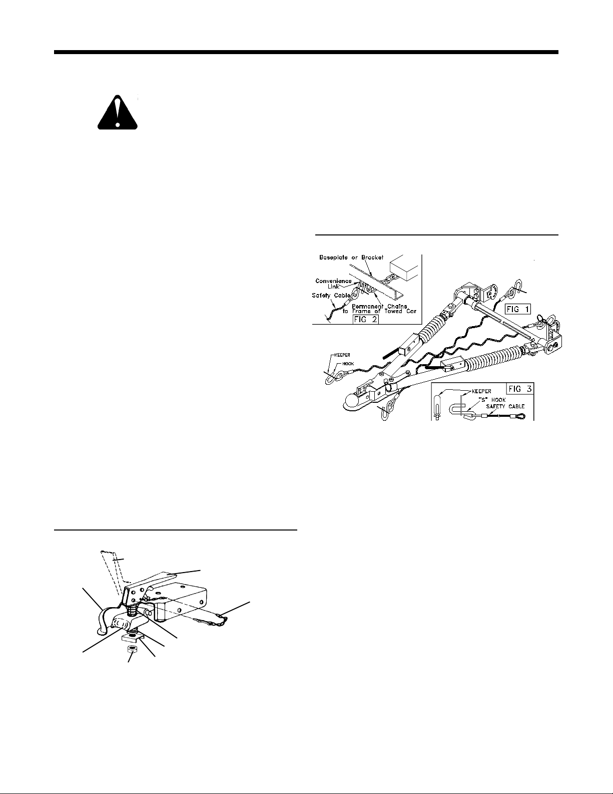
SAFETY CABLE INSTALLATION
1. Using the cable hooks, attach the cables to a solid
part of the chassis of the towed vehicle or to the
bracket convenience links on unibody cars. Slip the
end of the hook through the neoprene keeper to
prevent the hook from unhooking. (See Fig. 3)
NOTE: It is best to have permanent chains that
connect the convenience links to the frame of the
car. (See Fig. 2)
2. Cross the two safety cables under the tow bar. (See
Fig. 1) NOTE: Do not wrap around legs or damage
could occur to rubber boot.
3. Using the cable hooks, attach the opposite ends of
the cables to a solid part of the chassis of the towing
vehicle if at all possible. Slip the end of the hook
through the neoprene keeper to prevent the hook
from unhooking. (See Fig. 3)
Ball
Clamp
Lock Nut
Light Spring
Heavy Spring
Channel Lock
1.Using a 3/4" socket, tighten or loosen the nut until
firm contact between coupler and ball is established.
2.Check ball to housing tension periodically and
tighten if needed.
3.Lightly lubricate the ball.
292-2098 4/98 1 of 6
4. Adjust slack so that the cables cannot touch the
ground or become caught beneath the ball. If either
of these things happen, the cables may become
damaged and ineffective. DO NOT USE DAMAGED
CABLES!
5. If BX8805 or BX8806 cables are not used, be sure
each cable or chain used has at least the load rating
of the coupler (5000 lbs.).
Page 2
INSTALLATION / ADJUSTMENT
CAUTION: As with any mechanical product, care
should be taken during installation and operation, to
prevent your fingers from being pinched.
INSTALLATION
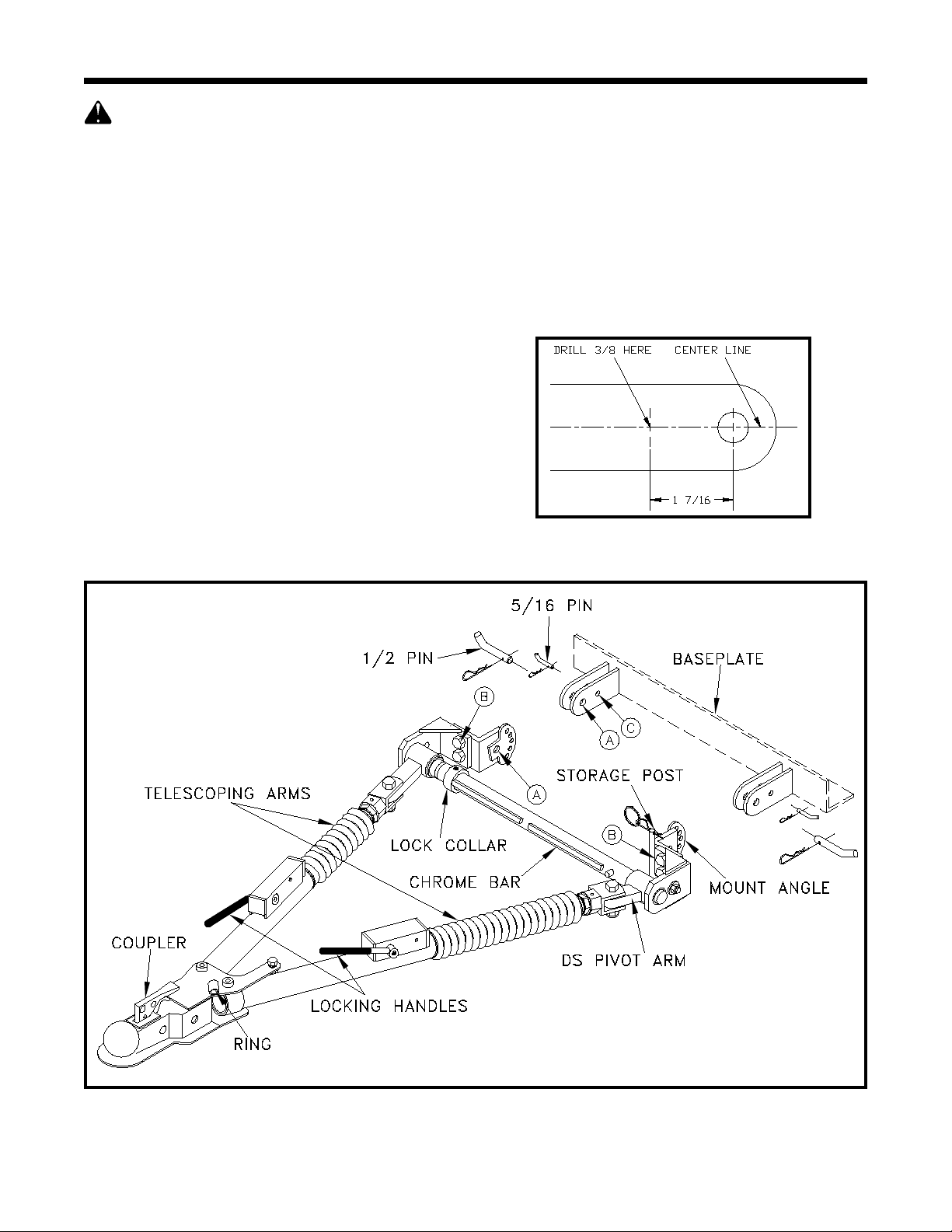
1. Refer to figure 1 while installing the tow bar. Hold
the Tow Bar in position with its tabs aligned inside
the baseplate tabs. Insert the 1/2 in. diameter pins,
provided with the baseplate, through the holes
labeled "A". Be sure to secure the pins with the
hairpin clips provided.
NOTE: If the tabs do not line up, the mount angles
on the tow bar can be adjusted by loosening the
bolts labeled "B". Be sure to tighten the bolts when
finished.
2. Fully extend the tow bar. (See Extending Tow Bar)
Hold the coupler parallel to the ground and rotate the
tow bar up or down until the top surfaces of the
mount angles are parallel with the coupler. Insert the
5/16 in. diameter pins through holes labeled "C" in
the baseplate and the nearest hole in the tow bar
tab.
NOTE: On baseplates manufactured prior to 1991,
these holes "C" must be drilled. Using a 3/8 drill bit,
drill holes on the center line of the baseplate tabs, 1
7/16 inches from the center of the existing hole.
(Figure 2) Be sure to secure the pins with the hairpin
clips provided.
3. Fold the tow bar for storage. (See Unhooking /
Folding section)
4. DEALER OR INSTALLER: BE CERTAIN USER
RECEIVES INSTRUCTION SHEETS.
Figure 2
Figure 1
292-2098 4/98 2 of 6
Page 3
HOOKING UP / EXTENDING
HOOKING-UP TO THE TOWING VEHICLE
Make sure you are able to identify the tow bar parts,
(Figure 1), before proceeding.
1. Release the clip.
(Figure 3) Using your
right hand, raise the
front end of the tow
bar and begin to slide
the DS pivot arm
across the chrome
bar. Important:
Keep the front end of
the tow bar up to keep
pressure off of the
slide rail.
2. Slide the DS pivot arm all the way to the right side
(drivers side), over the safety stop on the forward
side of the chrome bar, and against the edge (Figure
4). Once against the edge, roll the front of the tow
bar forward and down. The tow bar leg is now
locked into position and ready to use.
HITCHING UP COUPLER
1. Position the towing vehicle on a level surface with
approximately 100 ft. to 200 ft. of straight driveway
ahead and engage the parking brake. (Later, You
will be driving straight ahead to latch the legs when
extending the tow bar.) Position the towed vehicle
behind the towing vehicle in the approximate towing
position and engage the parking brake of the towed
vehicle.
Figure 3
EXTENDING TOW BAR
Caution: It is possible to extend the tow bar by
driving away with the towing vehicle. As you drive
away, the towed vehicle will wander around until,
eventually, both sides may lock. Even though they
may lock this way, we DO NOT recommend towing
any vehicle until the operator has confirmed that
the leg latches have been properly locked as
outlined below.
1. On the towed vehicle; disengage parking brake, set
up the transmission for towing, (See SAFETY
section - Page 1, Item 2) and unlock the steering
wheel. Drive the towing vehicle straight forward
approximately 50 ft. to100 ft. or until the locking
handles are engaged and locked. (When locked they
will "pop" up)
NOTE: If only one locking handle is locked, simply
turn the top of the towed vehicle's steering wheel
towards the unlocked side, approximately 1/2 to 3/4
turn, before continuing forward. Check to insure both
legs are latched properly before towing.
IMPORTANT: The steering wheel on the towed
vehicle must be unlocked at all times while being
towed. Failure to do so will create hazardous driving
conditions.
2. Install safety cables or chains and lighting. (See
safety cable installation - page1).
2. Adjust the coupler. (See Cplr Fit Adjstmnt - Pg. 1)
3. Pulling from the coupler, the arms will now telescope
out for self alignment. Place the coupler on a 2" ball
and lock the coupler by pushing down on the locking
lever. (See coupler fit adjustment) Important: For
safety, you should put the pin provided, a padlock, or
a bolt with nut through holes on the coupler lever. A
BX8860 padlock is recommended.
Figure 4
Safety Stop
DS Pivot Arm
292-2098 4/98 3 of 6
Page 4

FOLDING / MAINTENANCE
UNHOOKING / FOLDING
1. Park the towing vehicle with vehicle in tow, in a
straight line, on a flat, level surface to insure
minimum pressure is exerted on the tow bar legs.
This will aid in releasing the locking handles.
Engage the towing vehicle parking brake.
Place the towed vehicle either in park for automatic
transmissions or securely in first gear for manual
transmissions. Unhook the lighting and safety
cables.
2. Push straight down on the end of the locking handles
to release each leg.
3. Remove the coupler from the ball.
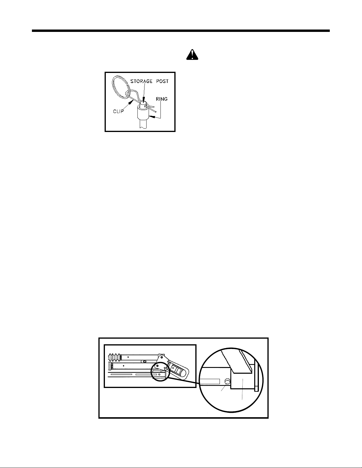
4. With the driver's side locking handle now pressed
down, slide arm in toward car. Swing the tow bar up
and back until the coupler is pointing up, and the DS
pivot arm is free to slide the arm left (past the safety
stop and slide rail) for storage. Now lower the "ring"
(welded on top the coupler) down over the storage
post and insert the clip. (Figures 1 & 3)
MAINTENANCE
1. This tow bar requires periodic maintenance. It will be
subjected to road dirt and weather during use. The
following tips will help maintain the condition of your
new tow bar.
2. Keep the tow bar covered when not in use, on or off
of the towing vehicle. This will cut down on the dust
and dirt build up on the inside legs and latches of the
tow bar.
3. Periodically clean the entire surface of the tow bar
with a mild soap and water solution. Wipe dry with a
clean cloth.
LUBRICATION
1. Approximately once per year you should remove the
small cable ties holding the rubber boots on the legs,
slide the boots back, and apply a light coat of
multipurpose grease to each of the inside legs to
insure smooth operation. Secure each boot back in
place with an 8 inch nylon cable tie (available at
most automotive and hardware stores. (Figure 5)
Figure 5
292-2098 4/98 4 of 6
Page 5

292-2098 4/98 5 of 6
REPLACEMENT PARTS
IMPORTANT: Use only genuine factory replacement parts on your Tow Bar. Do not substitute homemade or nontypical parts. If a bolt is lost or in need of replacement, for your safety and the preservation of your Tow Bar, be sure to use a replacement bolt of the same grade (Usually Grade 5).
Repair parts may be ordered through your nearest Automatic dealer or distributor.
Page 6

Ref. Qty. Part Description
No. No.
1 2 207-0735 .............................. Locking Handle, SS
2 1 61-4142 ...... Passenger Side Round Outside Leg
3 1 61-4144 .............. Driver Side Round Outside Leg
4 2 61-4149 ................................. Pivot Arm Receiver
5 1 61-4150 ...................... Passenger Side Pivot Arm
6 1 61-4151 ............................. Driver Side Pivot Arm
7 1 61-4990 ................... Coupler Assembly, DM7007
293-0273 .................. Class III Coupler Repair Kit
8 2 62-3311 ................................. Latch Handle Assy.
9 1 62-3235 ............. Driver Side Inner Leg Assembly
10 1 62-3236 ..... Passenger Side Inner Leg Assembly
11 - 84-0024 ...... Driver Side Complete Leg Assembly
12 - 84-0025 ..... Passenger Side Complete Leg Assy.
13 1 101-5158 .... Washer, 1 1/4 X 7/16 X 3/16, Plated
14 2 229-0469 ................. Spacer, Locking Handle, AL
15 4 201-0051 1/2-13 x 1 1/2 Hex Head Bolt, Grade 5
16 2 201-0283 ...... 1/2-13 x 2 Hex Head Bolt, Grade 5
17 1 201-0368 3/8-16 x 1 1/4 Hex Head Bolt, Grade 5
18 8 201-0504 ......................... 1/4-20 x 1/4 Set Screw
19 1 201-0517 ... 3/8-16 X 3/8 Socket Head Set Screw
20 1 201-0548 ........7/16-20 x 1 1/4 Hex Bolt, Grade 5
21 2 201-0557 ....... 1/2 X 2 1/4 X 3/8-16 Shoulder Bolt
22 4 202-0094 ...................................... 1/2-13 Hex Nut
23 2 202-0071 .....................3/8 Flange Whiz Lock Nut
24 2 202-0143 .......................... 1/2-13 Essna Jam Nut
25 2 202-0144 ....... 3/8-16 Hex Nut w/ Nylon, Jamlock
26 1 299-0124 .... Passenger Side Attachment Bracket
27 1 203-0010 ................................... 3/8 Lock Washer
REPLACEMENT PARTS
Parts List
Ref. Qty. Part Description
No. No.
28 1 203-0011 ................................. 7/16 Lock Washer
29 2 61-3824 ...................... Mushroom Mount Bracket
30 1 203-0072 ... Machine Bushing, 10 Ga. x 1 1/2 x 1
31 2 203-0129 ...... 1 Inch Internal Tooth Lock Washer
32 1 207-0688 .......................... Driver Side Inside Leg
33 1 207-0689 ................... Passenger Side Inside Leg
34 2 220-0033 ............................. Spring Pin, 1/4 x 3/8
35 2 222-0068 ......................... Spring, Locking Handle
36 1 229-0210 ......................................1 1/2 Split Ring
37 1 229-0244 .................................. # 10 Hair Pin Clip
38 1 299-0128 ........................................... Storage Pin
39 2 229-0386 ................................................ Leg Stop
40 2 299-0247 .................. Locking Handle Bolt, Plated
41 2 250-0156 .......................................... Rubber Boot
42 2 250-0157 ............. Foam Grip, 3/8 X 3 5/8 X 5/64
43 2 290-0275 ..........................8 Inch Nylon Cable Tie
44 2 290-0328 ................. Cap Plug, Red, 1 1/2 Round
45 4 290-0332 ............. Cap Plug, Black, 1 1/4 Square
46 2 290-0364 ..........................9 Inch Nylon Cable Tie
47 1 292-0797 ....... Decal, Safety Cables (Not Shown)
48 1 292-1206 ........... Decal, Instructions (Not Shown)
49 2 299-0121 ................................................ Boot Nut
50 1 292-2097 .......... ID Sticker, BX4335 (Not Shown)
51 2 292-1035 ................. Decal, Blue Ox (Not Shown)
52 1 299-0279 .................. Tube, Lock Collar, Chrome
53 1 299-0126 ............................... Cross Tube, Plated
54 2 299-0234 ......................... Swivel, Locking Handle
55 2 290-0377 ...................................... Plastic Washer
292-2098 4/98 6 of 6
Page 7

RANGEFINDER III
TM
OPERATOR, PARTS, AND
INSTALLATION MANUAL
BX4335
RANGEFINDER III
Class III (5000 lb) 2 Inch Coupler
TOWING PRODUCTS DIVISION
TM
Tow Bar
Page 8

QUICK REFERENCE GUIDE
HOOKING UP & EXTENDING FOR TOWING
1. Align vehicles in towing position with straight driveway
ahead and parking brakes locked.
2. Slide driver side pivot arm across over safety stop.
Place ball coupler on 2 inch ball.
3. Drive towing vehicle forward until both legs are locked.
(Locking Levers Up)
4. Install safety cables and towed vehicle lighting.
5. Detailed instructions appear on pages 3-4.
TO BE VALID, THE WARRANTY CARD MUST BE
COMPLETED IN ITS ENTIRETY BY AN AUTHORIZED
DISTRIBUTOR OR DEALER AND SENT TO AUTOMATIC
EQUIPMENT MFG. CO., PENDER, NEBRASKA. FAILURE
TO DO SO WILL VOID THE WARRANTY.
UNHOOKING & FOLDING FOR STORAGE
1. Park vehicles in a straight line on level surface. Apply
towing vehicle parking brake. Place towed vehicle in
park or 1st gear for manual transmissions.
2. Remove safety cables and towed vehicle lighting.
3. Disengage leg latches. Slide driver side pivot arm
towards passenger side. Place coupler ring on
storage post and pin in place.
4. Detailed instructions appear on page 4.
Repair parts may be ordered through your nearest
Automatic dealer or distributor.
Product Safety Policy Statement
It is, and shall continue to be, a primary objective of Automatic Equipment Manufacturing
Company to provide customers with safe and reliable products. Automatic will, and has, established safety procedures in product design, manufacture, promotion and sales; and will coordinate
efforts to promote customer safety to the greatest extent possible. Each department has primary
responsibility for the promotion of safety under the guidelines of the Product Safety Committee.
WARNING: Insure that your towing vehicle is of adequate size to properly control
your towed vehicle. The weight and braking capacity should be large enough to handle
both vehicles in an emergency situation. Check your towing vehicle manufacturers
recommendations for towing, hitch load, and braking capacities.
292-2098 4/98
Automatic Equipment Mfg. Co. l One Mill Road, Industrial Park
Pender, Nebraska 68047
© 1997 Automatic Equipment
Mfg. Co. Pender, NE 68047
 Loading...