

Page 1
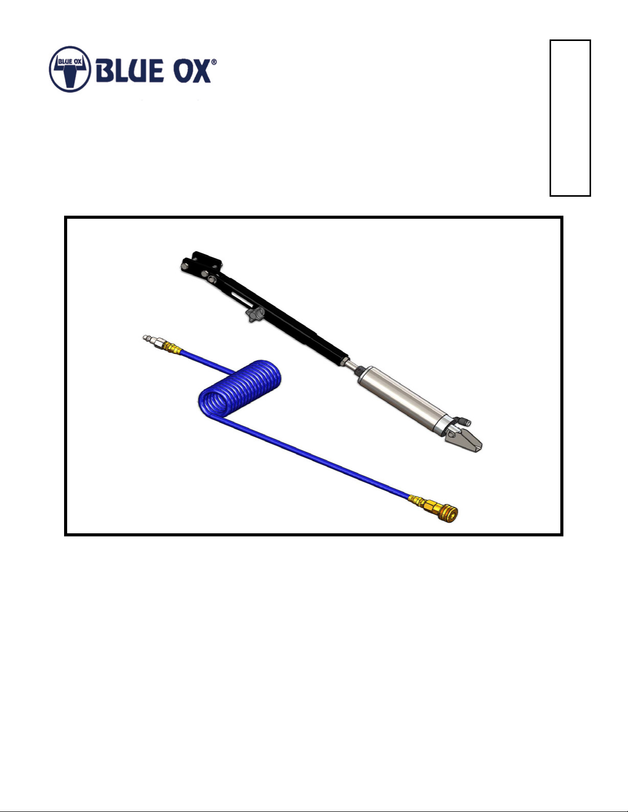
BRK4000
Push Cylinder BrakeSafe™
Installation Instructions
Serial Number
BRK4000
Push Cylinder BrakeSafe™
405-0312 Rev A Page 1 of 6 9/27/13
Page 2
BRK4000
TO LEFT BRAKE ACTUATOR
TO RIGHT BRAKE ACTUATOR
MAIN AIR IN
PROPORTIONAL
AIR TO TOWED
BRAKE SYSTEM
OPTION 1
BRAKE RELAY
PROPORTIONAL PILOT
TOP PORT
AIR SOURCE LOCATION,
CUT TUBE, INSTALL TEE
FITTING
OPTION 2
PILOT AIR FROM
BRAKE PEDAL
OPTIONAL SERVICE AIR SOURCES
1. UNUSED RELAY PORT
2. TEE INTO BRAKE HOSE PORT
AIR SOURCE LOCATION,
CUT TUBE, INSTALL TEE
FITTING
MAIN PORT
RUN TUBING TO
REAR OF COACH
AIR ACTUATOR
BOTTOM DRAIN PLUG
HYD. MASTERCYLINDER
FRONT
ONLY TAP INTO SERVICE BRAKE AIR. AIR SHOULD FLOW
FROM TUBE OR PORT WHEN BRAKE PEDAL IS APPLIED.
NOTE:
AIR OVER HYDRAULIC
ASSEMBLY IS LOCATED
AHEAD OF FRONT AXLE,
ON DRIVER’S SIDE
Push Cylinder BrakeSafe™
Installation Instructions
BrakeSafeTM is a proportional braking system that can be used on coaches with Total Air or Air Over Hydraulic
braking systems. With a BrakeSafeTM you will use your coach’s air brakes by tapping into the brake relay air
source.
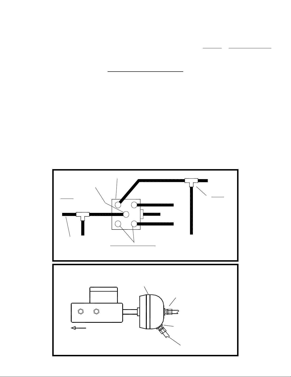
Locating Air Source On Coach
1. For coaches with total air brake systems, the brake relay is located ahead of the rear axle. This relay
has four to ve ports, some of which will be used. There is a right and left brake actuator hose coming
from this relay, these hoses go to the brake actuators of each rear tire of coach. There is a 3/8” O.D. pilot
tubing coming from one of the four ports coming from the brake relay. This is the SERVICE port that is the
preferred place to connect into proportional air that receives pilot air from the coach’s brake pedal. If this
port has a 3/8” hose coming from it, use the furnished tee tting. Cut the tubing and push the tubing into
each side of the tee tting, making sure the tubing is bottomed into the tting. On the bottom of some relay
valves there are four ports, three are used, the other has a 1/2” pipe plug. Remove this plug and install a
1/2”pipe to 3/8” tube tting. There should be no pressure coming from the port, unless the brake pedal is
pushed down. If there is, you need to look for another port. If your coach needs a tting that is not supplied,
most hardware stores have brass pipe ttings. (Figure 1)
2. For coaches with air over hydraulic braking systems, the air over hydraulic assembly is located in front
of front axle on the driver’s side. There is a drain plug on the bottom side of the air actuator, take this plug
out and install a 3/8” tube connector. (Figure 2)
Figure 1
Figure 2
405-0312 Rev A Page 2 of 6 9/27/13
Page 3

BRK4000
Push Cylinder BrakeSafe™
Installation Instructions
3/8” Tubing Installation On Coach
3. Push the supplied 3/8” DOT tubing into the tee tting or the pipe to tube tting making sure it is bottomed
into the port. Route and secure the 3/8” DOT tubing making sure to route away from hot parts. Once you
get to the rear of the coach with the tubing, secure the Coach Mounting Bracket with 1/4”-20 x 1-1/4” bolts
and 1/4”-20 lock nuts in a convenient location on the bumper. Then mount the bulkhead tting, 3/8 tube
tting, and QD coupler to this mount bracket as shown in Figure 3. Cut the extra 3/8” DOT tubing off and
then push into the pipe to tube tting.
1/4” Tubing Installation On Towed
4. Mount the Towed Vehicle Bracket with the 1/4”-20 x 1-1/4” bolts and 1/4”-20 lock nuts to the towed vehicle
in a convenient and secure location. Then mount the QD plug and 1/4” bulkhead to this bracket. Route the
1/4” tubing thru the driver side engine compartment making sure not to run tubing along hot parts. Push
tubing thru an existing grommet in the rewall. If there isn’t a hole, drill a new hole and install a grommet.
Continue routing the tubing behind driver side kick panel, then under the door sill molding. End the routing
under the driver seat, making sure to leave enough to hook-up to the push cylinder. Cut any excess off.
Towards Towed Vehicle
1/4" Tubing
Towed Vehicle Mounting Bracket
Male QD Fitting
Self-Coil Hose
Female QD Coupler
Figure 3
Coach Mounting Bracket
Towards Coach
3/8" Tubing
405-0312 Rev A Page 3 of 6 9/27/13
Page 4

BRK4000
Push Cylinder BrakeSafe™
Installation Instructions
Push-Cylinder Installation
5. Install the brake pedal brackets 3/4” above the brake pedal using the 1/4”-20 x 1-3/4” hex bolts and 1/4”-20
lock nuts. Select a suitable location for the Anchor Bracket, preferably as close to the drivers seat as you
can go, still being able to reach the brake pedal. The bracket also needs to be in line with the brake pedal.
Remove the air cylinder assembly from the anchor bracket by pulling the quick release pin and screw the
bracket to the oor with the #10 screws supplied. Reinstall the air cylinder assembly back into the anchor
bracket. Loosen the 5/16” plastic knob and adjust the length of the assembly until the pin on the end of the
assembly hooks onto the pedal brackets. Retighten the plastic knob on the assembly.
Figure 4
Pedal Brackets
3/4”
Air Cylinder
Assembly
Anchor Bracket
Plastic Knob
405-0312 Rev A Page 4 of 6 9/27/13
Page 5

BRK4000
1
22
24
15
18
23
19
17
2
20
20
20
6
11
16
25
31
27
4
3
32
29
26
10
30
14
9
12
28
5
13
33
21
8
7
Push Cylinder BrakeSafe™
Installation Instructions
Item No. Part No. Description Qty.
1.................................... 61-7125 ................................ BRK4000 Inner Adjustment ......................................................1
2.................................... 61-7126 ................................ BRK4000 Outer Adjustment .....................................................1
3.................................... 293-1318 .............................. Self-Coil Air Hose, 10ft .............................................................1
4.................................... 293-1319 .............................. 1/4” T Bulkhead Adapter ........................................................... 1
5.................................... 293-1320 .............................. 3/8” P Bulkhead Adapter ........................................................... 1
6.................................... 293-1344 .............................. 1/4” N2U Pipe Elbow ................................................................1
7.................................... 293-1511 ............................... Air Cylinder, 1-1/2” Bore x 3” Stroke ......................................... 1
8.................................... 101-8306 .............................. BRK4000 Anchor Bracket ......................................................... 1
9.................................... 105-1479 .............................. Towed Vehicle Mount ................................................................1
10.................................. 105-1480 .............................. Coach Mount ............................................................................1
11 .................................. 153-0085 .............................. 1/4” Nylon Tubing, 15’ ............................................................... 1
12.................................. 153-0112 ............................... 3/8” DOT Nylon Tubing, 25’ ......................................................1
13.................................. 153-0113 ............................... 1/4” Nylon Tubing x 6”L .............................................................1
14.................................. 201-0204 .............................. 1/4”-20 x 1-1/4” Hex Head Bolt, Grade 5, ZP ...........................4
15.................................. 201-0367 .............................. 1/4”-20 x 1-3/4” Hex Head Bolt .................................................2
16.................................. 201-0708 .............................. #10-16 x 1-1/2” Self Drilling Screw ...........................................2
17.................................. 201-0947 .............................. 5/16”-18 x 1-1/2” Carriage Bolt .................................................1
18.................................. 202-0102 .............................. 1/4”-20 Hex Nylon Lock Nut, ZP ...............................................6
20.................................. 229-0679 .............................. Fitting Adapter Set ....................................................................1
21.................................. 229-0945 .............................. 3/8” x 1” Quick Release Pin ......................................................1
19.................................. 203-0001 .............................. 1/4” Flat Washer, ZP ................................................................. 1
22.................................. 290-0411 ............................... 5/16”-18 Plastic Knob ............................................................... 1
23.................................. 293-1266 .............................. Pedal Bracket, Small ................................................................1
24.................................. 293-1267 .............................. Pedal Bracket, Long .................................................................1
25.................................. 293-1321 .............................. 3/8” x 1/4” Tube Fitting ..............................................................1
26.................................. 293-1322 .............................. QD Coupler ...............................................................................1
27.................................. 293-1323 .............................. QD Coupler ...............................................................................1
28.................................. 293-1324 .............................. QD Plug ....................................................................................1
29.................................. 293-1325 .............................. QD Plug ....................................................................................1
30.................................. 293-1330 .............................. Rubber Dust Plug .....................................................................1
31.................................. 293-1331 .............................. Dust Cap ...................................................................................1
32.................................. 293-1341 .............................. 3/8” Tube Tee ............................................................................1
33.................................. 293-1510 .............................. Hose Union, Straight, 1/4” to 1/4” .............................................1
405-0312 Rev A Page 5 of 6 9/27/13
Page 6

BRK4000
Push Cylinder BrakeSafe™
Installation Instructions
BRAKESAFE
TM
START-UP CHECKLIST
1. CONNECT TOWED VEHICLE TO THE COACH IN THE NORMAL WAY. IF BREAK-AWAY SYSTEM IS USED,
CONNECT LANYARD WIRE BETWEEN COACH AND TOWED VEHICLE.
2. CONNECT THE SELF-COILING AIR LINE TO THE COACH AND TOWED VEHICLE. MAKE SURE THE SLEEVE
CLICKS FORWARD ON THE QD COUPLER, THIS WILL ENSURE THE PLUG AND COUPLER ARE LOCKED.
3. MAKE SURE ALL HOSES ARE PLUGGED IN, AND BOTTOMED INTO FITTINGS.
4. WITH THE TOWED ENGINE OFF, PUMP THE BRAKE PEDAL SEVERAL TIMES TO DEPLETE VACUUM OR
POWER BOOST IN THE TOWED’S POWER BRAKES. THIS IS VERY IMPORTANT, AS OVER BRAKING WILL
OCCUR IF NOT COMPLETELY DEPLETED!!
5. START THE COACH ENGINE AND BRING THE AIR PRESSURE UP TO PRESSURE SWITCH SETTING. APPLY
THE COACH BRAKES SEVERAL TIMES AND WITNESS THE BRAKE PEDAL MOVEMENT IN THE TOWED
VEHICLE.
6. TURN IGNITION OF THE TOWED VEHICLE TO THE ACCESSORY POSITION, TO UNLOCK STEERING WHEEL.
DISCONNECT CHECK LIST
1. DISCONNECT SELF-COILING HOSE AND TOW BAR FROM THE TOWED VEHICLE AND COACH. INSTALL
PLUG AND CAP ON THE AIR DISCONNECTS, TO KEEP WATER AND DIRT OUT OF THE SYSTEM.
2. DISCONNECT THE PUSH CYLINDER FROM THE BRAKE PEDAL.THE TOWED VEHICLE IS NOW READY TO
DRIVE AWAY.
CUSTOMER SERVICE COMMITMENT
Blue Ox® is committed to providing you with exceptional customer care throughout your lifetime
with our products. Our team is here to assist you with any questions you may have regarding the
performance of your product. Simply call (402) 385-3051 and you can speak with our customer care
team.
Additionally, please visit our website to see which rallies our Destination America team will be
attending. For a nominal fee, our service technician will service your towing system to ensure it’s in
proper working condition. Also, as a commitment to our customers, should you visit our factory, you
can stay at our full service Blue Ox® campground at no charge along with enjoying a factory tour.
Again, thank you for being our customer and for the condence you have shown in the performance
of our products. It is because of customers like you we enjoy the success we have today.
One Mill Road, Industrial Park
Pender, Nebraska 68047
© 2013 Blue Ox
Phone: (402) 385-3051
Fax: (402) 385-3360
www.blueox.com
405-0312 Rev A Page 6 of 6 9/27/13
 Loading...