

Page 1
.
e
c
n
e
d
fi
n
o
c
g
n
i
k
a
r
b
f
o
l
e
v
e
l
®
Patriot
Braking System
Owner’s Manual
Patent Pending
BRK2010
w
e
n
A
THANK YOU
for purchasing a Patriot® braking system from
Blue Ox. We’ve organized this manual to make
your installation simple and as trouble-free
as possible. Please read before operating the
brake. Keep your sales receipt and this manual
in a safe place so that both are available for
future use if needed.
Read and understand fully these instructions
prior to the use of this product.
Page 1 of 16 405-0084 Rev. B 7/8/10
Page 2

Blue Ox®
prepp
p
ai
a
d,
d,
and in Au
tics s
ol
ol
e
e
d absol
ect
L
nt
y
y
y
y
Co
w
w
wa
thehe
o
r
p
pu
pu
.
und this
wa
w
rranty will be e ective only when a copy of the original invoice, showi
ng
dddate ana
a
d place of
n
y
ro
o
pe
p
tioon
u
ta
a
se
s
G
od
hehe u
gugugu
idele
in
ed
i
inststctio
ional mama
d
by
A
.
is ww
do
o
noro
ma
l
l
w
ar
n
o
.
Wa
r
r
su
mes no
p
ns
ib
il
y
t
o the owwwn
er for los
u
o
f
f
t,
l
s
ofofof
t
im
e,ee
nc
conv
y
yy y
m
g
qu
ential ootheis Includi
ng
but not li
to mil
expense of t
g
p
re
tu
ha
nics travel ti, te
le
ph
on roa
d
ve
l,
da
mage t
o
p
pe
ni
ng
n
s.
O
R
F
OR
CL
US
UT
OM
NS
EQ
U
U
NTIAL DAMAGES FOR
B
EACH OF ANY EXPRESS OR IMPLIED WARRANTY ON THS
UCT. EXCEPT TO THE EXTENEN
EN
LLAW, ANY IMPLIED WA
RR
ES
S FO
O
O
UCT IS
One-Year Limited Warranty
Automatic Equipment Manufacturing Company (“Automatic”) warrants to the original ( rst) retail purchaser this
product, manufactured by Automatic, shall be free from defect in material and workmanship under normal use
and service for a period of one year from the date of delivery.
During said one-year period, Automatic will repair or replace any parts that have been returned by the original
purchaser, to the factory, transportation prepaid, and in Automatics sole and absolute opinion found to be
purchaser, to the factory, transportation
defective.
f
iv
Limitations on Warranty Coverage:
imitations on Warra
Coverage under this warranty will be valid only if the customer warranty card is returned by the original purchaser
Coverage under this
within 30 days of purchase.
within 30 days of
Coverage under this warranty will be e ective only when a copy of the original invoice, showing date and place of
purchase, accompanies any claim for warranty. is warranty is NON TRANSFERABLE.
purchase, cmpans any claim for warranty. is warranty is NON TRANSFERABLE.
is limited warranty will not cover, in any way or form, any alleged damages caused by incorrect or improper
is limited warra
installation, improper use, modi cation or neglect of product, failure to properly service and maintain, misuse,
installa
act of God, accident or failure of the user to follow guidelines contained in the instructional material provided by
act of
Automatic.
utomtic
is warranty does not cover normal wear and tear, paint or rust.
Warrantor assumes no responsibility to the owner for loss of use of product, loss of time, inconvenience or
any other damage consequential or otherwise. Including, but not limited to mileage, expense of transporting
an
of product, return shipping expense, mechanics travel time, telephone, road service, towing, and rental during
repairs, travel, lodging, loss or damage to personal property or loss of earnings.
pairs, tra
REPAIR OR REPLACEMENT AS SET FORTH IN THIS LIMITED WARRANTY IS THE SOLE EXCLUSIVE
REMEDY OF THE PURCHASER. AUTOMATIC SHALL NOT BE LIABLE FOR ANY INCIDENTAL OR
CONSEQUENTIAL DAMAGES FOR BREACH OF ANY EXPRESS OR IMPLIED WARRANTY ON THIS
PRODUCT. EXCEPT TO THE EXTENT PROHIBITED BY APPLICABLE LAW, ANY IMPLIED WARRANTY
OF MERCHANTABILITY OR FITNESS FOR A PARTICULAR PURPOSE ON THIS PRODUCT IS LIMITED
IN LENGTH TO THE DURATION OF THIS WARRANTY.
Some states do NOT allow the exclusion of incidental of consequential damages, or allow limitations on how long
an implied warranty lasts, so previous limitations or exclusions may NOT apply to you. is warranty gives you
speci c legal rights and you may also have other rights which vary from state to state.
Automatic reserves the right to make changes or add improvements to its product at any time without any
obligation to make such changes to previously manufactured equipment.
No liability is assumed for bodily injury that may be in icted on the purchaser, operator, spectator or general
public who is in the general area while this equipment is in use.
, improer
, accident orfailure of t
arranty
antor as
other da
roduct,
PAIR
MEDY OF THE PURCHASER. A
OD
MERCHANTABILITY OR FITN
LENGTH TO THE DURATION OF THIS WARRANTY.
REPLACEMENT AS SET
rchase
will not cover, in any way or form, any alleged damages caused by incorret o imp
es no cover
res
e conse
rn shiping expense, mec
lodging, loss or
verage:
rranty will be valid only if the customer warranty card is returned by
se, modi cation or neglect of product, failure to properly service and min
ser t follow
and tear, pai
it
rsonal property or loss of ear
TH IN THIS LIMITED WARRANTY IS THE SOLE EX
ATIC SHALL NOT BE LIABLE FOR ANY INCIDENTAL O
T PROHIBITED BY APPLICABLE
R A PARTICULAR PURPOSE
toma
es contain
r rust
s of
,
pr
mited
ute opinion found to be
riginal purchase
in, mi
n the
uc
os
ea
,
service, towing, and rental dring
N THIS PROD
i
terial provide
nienc or
ransportin
r
,
IVE
ANTY
LIMITED
WARRANTY REQUEST PROCEDURE:
If your Automatic product develops a defect during the warranty period, promptly notify Automatic Customer
Care. Until such notice is received, Automatic will not be responsible for any repairs or replacement.
Upon receipt of notice from you, Automatic will have a choice of options in repairing or replacing any part it
determines in its sole and absolute desecration to be defective. 1.) Customer Care may require you, at your
own expense, to deliver or ship the part to the factory for evaluation. ey will issue a “Return Merchandise
Authorization” (RMA) number if this is required.
2.) Any part that is, in Automatic’s sole and absolute judgment, found to be defective in material or workmanship,
will be repaired or replaced, at Automatic’s option without charge for parts or labor. At Automatic’s option, new,
refurbished or improved parts may be used in the repair or replacement of warranted items or replacement
products.
Blue Ox® Division
Automatic Equipment Mfg. Co.
P.O. Box 430
Pender, Nebraska 68047
www.blueox.com - (402) 385-3051
Page 3 of 16 405-0084 Rev. B 7/8/10
Page 3

Product Information & Table of Contents
Equipment Information Record
Table of Contents
Customer Name: ______________________
Date Purchased: _______________________
Purchased From: _______________________
Address: ______________________________
City:__________State: ___ Zip Code: ______
Phone Number of Dealership: ____________
Installed By: __________________________
Service #: _____________________________
Model #: ______________________________
Serial #: ______________________________
Notes: ________________________________
______________________________________
___________________________________________________________________________
___________________________________________________________________________
!
WARNING
-FOR YOUR SAFETY-
Fully understand these instructions before
installing. Improper installation and/or
operation can create a hazard which can
cause serious injury, property damage
or death. Improper installation and/or
operation will void the warranty.
Page 2
Warranty Information
Page 3
Equipment Information Record
Table of Contents
Customer Care Information
Page 4
Welcome to the Blue Ox Experience
Care and Maintenance
Page 5
Unpacking
Parts List Itemization
Page 6
e Patriot® Illustrated
Pages 7-8
Installation Setup
Page 9 & 10
Error Messages
Pages11
Breakaway System
Pages 12
Disconnecting
Pages 13
Accessories
At Blue Ox® we pride ourselves in
o ering exceptional customer service
to our valued customers.
If you have any questions, comments,
or concerns please feel free to contact
a member of our Customer Care Team
by calling (402) 385-3051.
Page 4 of 16 405-0084 Rev. B 7/8/10
DEALERS AND DISTRIBUTORS:
PLEASE give the instructions to the customer so
they fully understand the setup, operation, and
safety precautions of this braking system.
Page 4

Welcome to the Blue Ox® Experience
Congratulations! You are now the proud owner of a Patriot® braking system.
Welcome to the Blue Ox® Family. e braking system that you have purchased combines quality
components with the latest in technology and style. We are con dent that these design features will
provide you with the conveniences you expect during your travels. A er you understand how to properly
and safely operate and care for your Patriot®, expect years of trouble-free operation and service backed by
a one year limited warranty.
In this manual, you will nd installation instructions. Please read all of the technical documents,
warnings, cautions, tips, and notes in this manual before attempting to operate your Patriot® for the rst
time. Improper installation, use or maintenance may result in malfunction causing personal injury or
property damage. Finally, don’t forget to ll out and return your warranty card or registering via our
web site at www.blueox.com within ten days of delivery date and upon the original serial number being
visible on the product and unaltered. For future reference, your serial number is located on the outside of
the manual packaging and is also located on the bottom of your Patriot® unit.
WARNING
!
Do NOT modify your Patriot® in
any way NOT authorized by Blue
Ox®, as it will void the warranty.
Care & Maintenance
Care and Maintenance of your
Patriot® Braking System
Your Patriot® unit requires a minimal amount
of care and maintenance. If you do not feel
con dent in your ability to perform the
occasional maintenance, consult your Blue Ox®
Dealer or Professional Installer, or see a Blue Ox
representative at a rally or race that you plan to
attend. e following will inform you of the areas
of your Patriot® that will need periodic inspection
and/or care and maintenance.
- REMINDER -
Proper installation and
use of this product is the
sole responsibility of the
purchaser.
Care
Do NOT use any type of solvent or spray cleaner
on the Patriot® braking system. e recommended
cleaning procedures for the Patriot® are to wipe
down the exterior with a damp cloth. Wipe down
with a dry cloth.
Store in a clean, dry place.
Maintenance
It may be necessary to occasionally lubricate the
brake bracket with silicone spray.
- REMINDER -
The maximum current that can be
drawn from the cigarette lighter
socket mounted on the Patriot is 2
amps.
WARNING
!
- USE ONLY GENUINE FACTORY
REPLACEMENT PARTS -
Do NOT substitute homemade or non-typical parts.
This may cause your brake to fail and result in injury
or death. If repair parts or components are needed,
you may order them through your nearest Blue Ox
Dealer or Distributor, or call our Customer Care Team
Page 5 of 16 405-0084 Rev. B 7/8/10
at (402) 385-3051.
®
Page 5
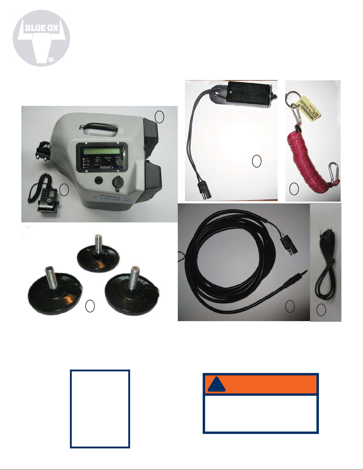
Unpacking your Patriot®
Remove the Patriot® and accessories from the shipping carton, review parts list and diagram below. Make sure
that you have the appropriate items shown below. If NOT, please contact a Blue Ox® Dealer or Distributor, or call
a member of the Customer Care Team at (402) 385-3051 to order replacement parts.
Patriot® Braking System
e Patriot® brake system is comprised of the Patriot® (with brake
bracket assembly).
Patriot®
1
2
Breakaway System
4
5
3
6
Contents:
1 Patriot® assembly 4 Breakaway Switch
2 2-Way RF In-Coach Controller 5 Breakaway Lanyard
3 Brake Feet 6 Breakaway Cable
7 Breakaway Extension
Tools &
Supplies
Required
Phillips Screwdriver
Wire Ties
Vise Grip
Rubber Grommet
Silicone Sealant
Page 6 of 16 405-0084 Rev. B 7/8/10
WARNING
!
Be sure the breakaway cable is
kept clear of the towbar, safety
cables, electrical cord or any
moving parts.
7
Page 6

e Patriot® Illustrated
Carrying Handle
Information
Display
Actuator Arm
One-button
Set-up
Brake “Claw”
Adjustable
Push Pad
On/O Switch
12 Volt, 2
Amp (Max)
Receptacle
RF Remote
Unit
Manual
Override Lever
Actuator Arm
When activated, extends to
press the brake bracket against
the towed vehicle’s brake pedal.
Page 7 of 16 405-0084 Rev. B 7/8/10
Page 7

Installation Setup
is section will explain how to install the
Patriot®.
Note: Prepare the car for towing. Attach the
tow bar.
In Towed Vehicle:
causing the brake lights to be activated. If the seat
can’t be moved forward far enough, an arm extension is
available. (see page 13)
Note: If using a breakaway, it must be connected before
turning on the unit.
6. Plug in power cord to cigarette lighter. Be sure there is
12 volt power. Indicator light will glow.
1. Open driver side door of towed vehicle, and push
driver seat back as far as possible.
2. Place BRK 2010 Patriot® on the oor.
3. Open “Claw” and place it on the brake pedal. (Fig. 1)
Fig. 1 Place claw on brake pedal
Note: The easiest way is to place the bottom of the claw
under the pedal rst, then slide the top of the claw over
the top of the pedal.
7. Turn on the power switch. (Fig. 2) Display will read
initializing.
8. When the display reads “Position Arm Then Press
Setup,” press the JOG switch to push slightly on the brake
pedal. (Fig. 3) The brake pedal should be depressed as
far as possible WITHOUT activating the brake lights.
Fig. 3 Adjust the brake pedal with the Jog Switch
4.The feet can be attached for proper height position. The
rubber boots may be removed to expose the grippers on
the feet.
Note: Do not store or transport with the feet attached
to the unit.
5. Slide the driver’s seat forward to touch push pads.
Adjust the push-pad up or down for proper height
position in relation to the seat.
Fig. 2 Turn on Power Switch
Note: Seat must be as far forward as possible without
Page 8 of 16 405-0084 Rev. B 7/8/10
9. Push the “SETUP” button.
The brake will stroke 3 (three) times then remain in the
ready position.
Note: If the brake extends fully and remains extended
without stroking three times, the seat is not far enough
forward. Turn the brake o then back on. Reposition the
seat as far forward as possible without causing the brake
lights to be activated then continue with Step 8.
Fig. 4 Push the Setup Button
Page 8

Fig. 5 RF in-coach controller mounted on dashboard
In the Motor Coach:
Find a sturdy, easy-to-reach location to mount the RF
in-coach controller. The dashboard is the suggested
mounting point, but anywhere that is secure and
accessible to the driver will work.
BRK 2010 Patriot®
Operating Instructions
1. Plug the 2-Way RF In-Coach Controller into an
available 12 volt outlet.
2. The large number on the display represents
the sensitivity setting of the Patriot® Brake; it will
automatically be set to 5 when activated.
3. Turn the “Gain” knob to the left or right to adjust
this setting. The lowest setting (0) puts the tow brake
on stand-by and will apply no pressure to the brake.
Settings 1 through 9 will incrementally increase the
pressure applied.
4. On the bottom of the RF Controller there is a Manual
Override Lever. Pressing down on this lever will cause
the Patriot® Brake to press down on the brake pedal.
Note: This is a progressive lever; the lever controls the
braking according to the level set on the RF controller.
This acts like a trailer brake and is useful in wet weather
to keep the towed vehicle in line.
5. If the error light turns on, Check the display screen on
the Patriot® Brake unit and refer to the list of possible
display messages for assistance (see Fig. 6). After
addressing the problem, turn o the Patriot® Brake and
restart the setup procedure.
Attaching the controller:
Using the Velcro provided, attach one side to the
desired mounting point, and the other side to the
controller.
Note: The Patriot® Brake can be used with or without
the RF controller. We recommend using the controller
for the operational feedback, but the brake can be set
without the RF controller.
If your remote is not receiving a signal or to pair a new or
unpaired remote module, perform the following steps:
On the Remote:
First, make sure the brake unit is plugged in and
turned on. Hold down the “Manual Override” lever while
plugging in the remote cord. Once the unit begins to light
up, you can release the lever. An “A” will appear on the
Remote LED screen indicating the unit is in “Search Mode”.
Once the remote changes from an “A” on the LED to another
character the remote is now paired and will remain so until
this procedure is repeated.
On the Brake Unit:
Turn power to the brake unit o . Make sure
the remote unit is plugged in. Firmly depress the
6. If a breakaway switch is installed and plugged in, the
“BK / AWAY ON” LED should be on. Follow the instructions
provided. The break-away switch should be installed
and plugged in before turning the brake on.
7. Anytime the towed vehicle is started up, the Patriot
needs to be reset.
8. Go through the set up procedure again if the unit is
shut o for any period of time and left in the toad or if
the battery goes dead.
JOG switch to the left AND simultaneously hold
down the SETUP button while powering on the unit.
Once the unit begins to light up you can release the
buttons. The screen should read “Remote Search”
and will only accept radio communication from the
energized remote device. Once it nds the remote,
it will automatically reset, and come up in normal
operation mode.
Each step should take approximately 10 seconds. Once a
set is paired, go through the normal setup and make sure
everything is functioning (make sure the Gain knob on the
remote changes the gain displayed on the remote itself and
also on the brake, and make sure that the Manual Override
actually applies the brakes).
Page 9 of 16 405-0084 Rev. B 7/8/10
Page 9

When installing the Patriot® on hybrids, the settings menu must
be accessed. To do this:
1. Hold down the setup button while turning the unit on, when it
lights up let go of the button.
2. Once it is finished initializing, the screen will read “MODE:
FORCE”. Hit the JOG switch to the left so that the screen now
reads “MODE: POSITION”. Press SETUP to select this setting.
3. The next screen will read, “MAX FORCE” Press SETUP
again at this screen.
4. The brake should read “SETTINGS SAVED!” and automatically restart.
These setting will be stored in the memory and remain until a user
goes through this procedure again and changes them.
In a Hybrid vehicle, the GAIN setting should always be kept
between settings 1 and 3.
This will address the issue of users repeatedly getting
REPOSITION BRAKE error during setup.
If a user gets the REPOSITION BRAKE error twice in a row
while trying to set up their brake, then they should do the fol-
lowing:
1. With the brake plugged in but powered off, hold down
the SETUP button while powering on the unit. Once it lights
up you can release the setup button.
2. Once it is finished initializing, the screen will read
“MODE: FORCE”. Hit the JOG switch to the left so that the
screen now reads “MODE: POSITION”. Press SETUP to select
this setting.
3. The next screen will read, “MAX FORCE” Press SETUP
again at this screen.
4. The brake should read “SETTINGS SAVED!” and automatically restart.
These setting will be stored in the memory and remain until
a user goes through this procedure again and changes them.
With these settings, the brake will work on ANY vehicle.
For a traditional vehicle, the GAIN setting should be kept
between settings 6 and 9.
In a Hybrid vehicle, the GAIN setting should be kept between
settings 1 and 3.
Error Messages
Error messages DO show up on the brake itself and NOT on the RF remote inside the RV. You are noti ed
of an error on the RF, but the error messages are displayed on the brake. In order for the breakaway switch
to work properly, it must be plugged into the brake before you turn the brake on. The following chart has
details of the error messages in the Patriot. Each error has a corresponding code number that will show up
in the remote. In Fig. 6 below, the rst ve rows and Flashing “A” are not errors, just the codes that will show
up during normal use.
LED Numeric Display Indication Description
Non-flashing “0” through “9” Control Unit in READY state (normal operation),
indicates current braking gain setting.
Flashing “0” or “A” Control Unit in RADIO SEARCH state (looking for
Remote Unit radio transmission to store MAC address).
Flashing “1” Control Unit in INITIALIZING state (retract actuator).
Flashing “2” Control Unit in POSITION state (manual jog).
Flashing “3” Control Unit in SETUP state (pump brake pedal 3
times).
Flashing “4”, with intermittent beep Control Unit in CAR BATTERY LOW state (retract
actuator, no braking function except breakaway).
Flashing “5”, with intermittent beep Control Unit in UNIT NOT LEVEL state (not currently
implemented).
Flashing “6”, with intermittent beep Control Unit in REPOSITION state.
Flashing “7”, with intermittent beep Control Unit in BREAKAWAY state (maximum
braking applied).
Flashing “8”, with intermittent beep Control Unit in BRAKING TIMEOUT state (retract
actuator, no braking function except breakaway).
Flashing C”, with intermittent beep Communications error (Remote Unit not receiving
radio transmissions from Control Unit).
Page 10 of 16 405-0084 Rev. B 7/8/10
Fig. 6
Page 10

Blue Ox Patriot
Detailed Explanation of Error Codes
Page 11 of 16 405-0084 Rev. B 7/8/10
Page 11

Breakaway System
Description of your product.
e Breakaway system automatically activates the Patriot® to apply the brakes on your towed vehicle in the event
the motorhome separates from the towed vehicle. is type of emergency system is required by most states and
provinces.
Installation
is section will explain how to install the Breakaway.
Mounting the Break-Away Switch
1. With the pin facing the motor home, secure the breakaway switch onto the front of the towed vehicle in a sturdy
location. This should be a convenient location which can
be easily reached, and if possible, on the driver’s side.
Note: The break-away switch must be mounted directly on
the towed vehicle and not to be installed on the tow bar
or bracket. The surface must be strong enough to hold
the break-away switch and allow for the pin to be pulled
out cleanly.
2. Make certain that the switch is securely attached, and
that the pin can be removed from the switch without any
interference. Plug the cable into the break-away switch.
3. Install the Break-Away Switch using a bolt and lock nut.
Do not use a self tapping screw.
Connecting the Break-Away Switch
to the Patriot® Brake
There are two di erent ways to attach the break-away
device to the Patriot® Brake. Use the method which is
most convenient for you.
Method 1: Through the rewall
1. Look for a preexisting hole in the rewall, if no hole exists,
drill a ½” diameter hole. Insert grommet into hole.
Note: Make sure not to damage any components on either
side of the rewall while drilling.
2. Find a path for the cable through the engine
compartment to the rewall. Use wire ties to secure the
cable. Make sure to avoid any hot or moving engine
parts.
3. Insert the cable into the grommet and pull the excess
slack into the driver’s compartment. Seal around and
inside of the grommet with silicone sealant.
4. Plug the cable into the Patriot® Brake.
Note: When not in use, the cable can be tucked away .
Method 2: Feeding the cable through the door/window
1) Find a path for the cable through the engine
compartment to the rear of the hood/base of the
windshield, on the driver’s side. Use nylon ties to secure
the cable so that it is avoiding any hot or moving engine
parts.
2) Either roll down the window and thread the cable
through, or open the door and thread the cable through.
Make sure excess slack is safely coiled inside the driver’s
cockpit. Once the cable is through and connected, close
the door/window.
Page 12 of 16 405-0084 Rev. B 7/8/10
Page 12

Disconnecting
is section will provide disconnecting information about the Patriot®.
Perform these steps each time you remove the Patriot®.
1. Turn o the Patriot. Unplug the Patriot®’s power cord from the 12-volt accessory outlet.
2. Adjust the driver’s seat as far back as possible.
3. Unhook the brake bracket from the brake pedal. Unplug the Breakaway clips from the
Patriot® control panel (if applicable).
!
CAUTION
4. Li the Patriot® out of the vehicle.
These settings are GENERAL
GUIDELINES ONLY and may
vary depending on conditions,
driver and/or the vehicles involved
in your particular towing situation.
!
CAUTION
Shut off the unit and unplug the
RF when you stop driving for the
day. Don’t leave the unit plugged
in all night, it could drain your car
battery.
To satisfy FCC RF exposure requirements for mobile
and base station transmission devices, a separation
distance of 20 cm or more should be maintained
between the antenna of this device and persons
during operation. To ensure compliance, operation at
closer than this distance is not recommended.
The antenna(s) used for this transmitter must not be
co-located or operating in conjunction with any other
antenna or transmitter.
This equipment has been tested and found to comply
with the limits for a Class B digital device, pursuant to
part 15 of the FCC Rules. These limits are designed to
provide reasonable protection against harmful
interference in a residential installation. This
equipment generates, uses and can radiate radio
frequency energy, and if not installed and used in
accordance with the instructions, may cause harmful
interference to radio communications. However, there
is no guarantee that interference will not occur in a
particular installation. If this equipment does cause
harmful interference to radio or television reception,
which can be determined by turning the equipment off
and on, the user is encouraged to try to correct the
interference by one or more of the following measures:
• Reorient or relocate the receiving antenna.
• Increase the separation between the equipment
and receiver.
• Connect the equipment into an outlet on a
circuit different from that to which the receiver is
connected.
• Consult the dealer or an experienced radio/TV
technician for help
Page 13 of 16 405-0084 Rev. B 7/8/10
Page 13

Patriot® Accessories
Ô
Ô
If you would like to order any of these accessory parts for your Patriot®, please contact a Blue Ox® Dealer or
Distributor, or call a member of the Customer Care Team at (402) 385-3051 to order these parts.
VW Brake Claw
2
This claw is designed to be used with the Patriot® primarily
when it is installed in a Volkswagen where the top section
of the claw does not t around the support holding the
brake pedal.. The part number is BRK2501.
Brake Rod Extension
If the seat can’t be moved forward far enough, this rod
extension is available to be inserted between the brake
claw and the actuator arm. Also if there is a low steering
column/dashboard which touches and interferes with
the brake, this extension can be used. The part number
is BRK2502.
Seat Sti ener
Ô
Ô
The seat sti ener works with any drop in tow brake on the market. It provides a larger surface area on the seat for the
brake system to push against. This means you get better, more responsive braking. If you continually get a “reposition
brake error” this will help solve that problem. To install: Put a piece of Velcro on the brake’s push pads and on the
outside of the seat sti ener. The brake’s push pads should line up and push against the outside of the “pockets”. The
part number is BRK2503.
Page 14 of 16 405-0084 Rev. B 7/8/10
Page 14

and
gu
g
iding princi
pl
p
es. In accordance with this objective, Blue Ox is
p
p
roud to
pr
p
ov
e e e
uch h
has
repai
d
g
en
e
a
l
ue O
ro
du
r 0 0000RV RRRal
l
Lo
okok
ok
r ouou
our Destin
er
ica or Blue Ox® se
e crew
s
he next rally oroo race th
tt
en
ueueue Ox® a
l
e
eins
al
li and
h
o
ur Par
k
n
R
es
a add
dd
dd
n,
B
cu
cu
sststomer
s
s
s
vivis
s
si
ac
totory
ry
y mayayy
adaavant
ag
ag
ag
f
ree use t he w
ppeded
RV p
yo
u, ou
an
a
d
appreciate
d
om
q
p
p
g
y
, p
p
Don’t rely on overburdened brakes. Instead, rely on a
complete braking system from the company synonymous
with safe, reliable RVing. Blue Ox®.
To fi nd the Blue Ox dealer nearest you,
visit www.blueox.com or call (402) 385-3051.
Serial Number
Customer Service Commitment
Blue Ox® is focused on providing exemplary customer service, as observed in our mission
statement and guiding principles. In accordance with this objective, Blue Ox® is proud to provide
services such as repairs and general maintenance of Blue Ox® products at over 150 RV Rallies. Look
services s
for our Destination America or Blue Ox® service crews at the next rally or race that you attend.
Blue Ox® also o ers educational seminars at rallies and through our Parks and Resort teams.
In addition, Blue Ox® customers visiting our factory may take advantage of free use of the well-
rs an
ationAm
soo
rs educatioal s
itio
equipped Blue Ox® RV park at no charge to you, our valued and appreciated customer.
ui
lue Ox®
Blue Ox®
er maint
ting ou f
ark at no
ce of B
rvic
at r
arg to
x® p
at t
throug
take
value
cts at ove
e of
s a
cu
ies.
at you a
ort teas.
er.
d.
ell-
© 2010 Blue Ox
Printed in the USA
Page 16 of 16 405-0084 Rev. B 7/8/10
Blue Ox • One Mill Road, Industrial Park • Pender, Nebraska 68047
Phone: (402) 385-3051 • Fax: (402) 385-3360 • www.blueox.com
 Loading...