

Page 1
TM
®
AVENTA
II
OPERATOR, PARTS, AND
INSTALLATION MANUAL
AVENTA
Class IV (10,000 lb) 2 Inch Receiver
© 1996,00,06 Blue Ox Division, Automatic Equipment Mfg. Co. • One Mill Road, Industrial Park
Pender , Nebraska 68047 • Phone 402-385-3051 • Fax 402-385-3360 • www .blueox.us
BX7335
® II
Tow Bar
Page 2
TM
SAFETY
DO NOT INSTALL, OPERATE OR USE THIS EQUIPMENT UNTIL THE FOLLOWING
OPERATING AND SAFETY INSTRUCTIONS HAVE BEEN READ AND UNDERSTOOD.
This symbol is used to bring attention to safety precautions and instructions.
When you see this symbol, be alert and pay attention to all instructions.
YOUR PERSONAL SAFETY IS INVOLVED.
1. Blue Ox Tow Bars should be used with cars
designed or modified to be towed.
2. Set the transmission for towing according to
the owners manual. Verify recreational
towing procedures in the vehicle owners
manual.
3. Unlock the steering wheel for towing to allow
the front wheels of the towed vehicle to
“track”.
4. Be sure the front end of the towed vehicle is
properly aligned. Unaligned vehicles will
cause poor tracking and abnormal wear on
the tires.
5. The use of safety cables or chains is
REQUIRED BY LAW. Model BX8805 (5ft) or
BX8806 (6ft) or the BX88169 (Class IV) cables
are recommended.
6. Check clearance between vehicles in a
turning situation.
7. Rear lighting is required on the towed car. A
BX8811 Wiring Kit, BX8834 Light Bar,
BX8847 (Saturns) or BX8869 (Bulb & Socket)
is recommended.
8. Prior to a towing trip, check to be sure all the
towing accessories and attachment points are
secure. Check for cracked welds and loose
bolts/pins on baseplate and tow bar. This is
important on all occasions, but particularly on
a new installation, when they should be
checked just prior to initial towing and again
after 100-200 miles of towing.
9. Do Not Back Up when towing. Damage to
both vehicles and towing system may occur.
10. Avoid sharp turns and rough terrain. Check
installation after any unusual event and
periodically on a long trip.
11. Do not use the Towed Vehicle for storing
luggage, etc.; you may exceed the towing
capacity of the Tow Bar and its accessories.
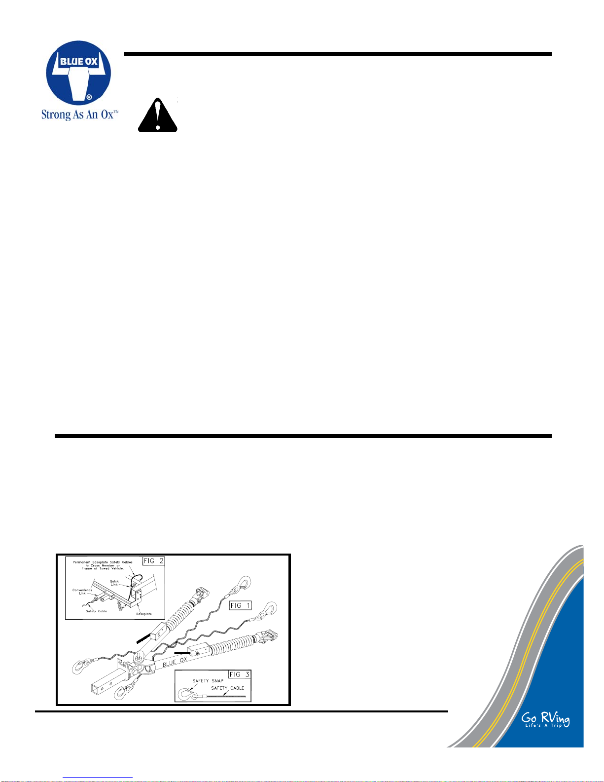
SAFETY CABLE INSTALLATION
1. Using the cable hooks, attach the cables to a solid
part of the chassis of the towed vehicle or to the
convenience links. Be sure that the spring loaded
hook closure retracts back to the closed position to
prevent the hook from disengaged. (See Fig. 3)
NOTE: It is best to have permanent saftey cables
that connect the convenience links to the frame of
© 1996,00,06 Blue Ox Division, Automatic Equipment Mfg. Co. • One Mill Road, Industrial Park
Pender , Nebraska 68047 • Phone 402-385-3051 • Fax 402-385-3360 • www .blueox.us
292-2078 4/06 1 of 8
the car. (See Fig. 2)
2. NOTE: Do not wrap safety cables around legs
or damage could occur to the rubber boots. If
it is necessary to remove slack from the cables,
wrap each once around their respective tow
bar legs in front of the latch housing and then
cross them under the tow bar. (See Fig. 1)
3. Using the cable hooks, attach the opposite ends of
the cables to a solid part of the chassis of the
towing vehicle if at all possible. Slip the end of the
hook through the neoprene keeper to prevent the
hook from unhooking. (See Fig. 3)
4. Adjust slack so that the cables cannot touch
the ground or become caught beneath the
receiver area. If either of these things
happen, the cables may become damaged
and ineffective. DO NOT USE DAMAGED
CABLES!
5. Be sure each cable or chain used has
at least the load rating of the tow bar
(5,000 lbs).
Page 3
TM
INSTALLATION
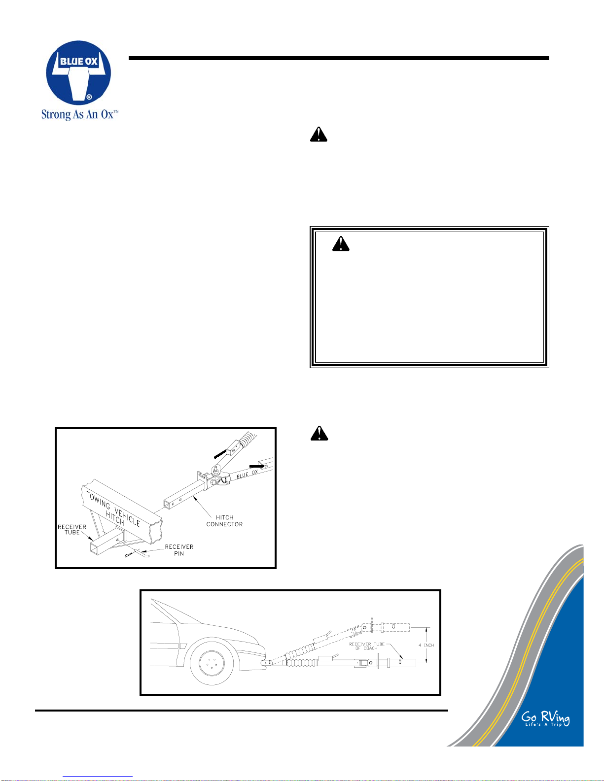
TOW BAR INSTALLATION (Towing Vehicle)
1. Slide the hitch connector into the receiver tube of
your towing vehicle hitch. Secure the receiver pin
provided into one of the two holes of the hitch
receiver. The inside hole of the receiver tube is
most commonly used. (Figure 1) Blue Ox offers
receiver and towbar lock sets (BX88101)
(BX88177) that help prevent theft. Contact Blue
Ox for more information.
2. Proceed with hooking up towed vehicle. (Page 3)
3. DEALER OR INSTALLER: BE CERTAIN USER
RECEIVES INSTRUCTION SHEETS.
NOTE: The configuration of the rear of your towing
vehicle will determine how far you can slide the
hitch connector into the receiver tube. Later, when
the tow bar is folded, you may need to change
which set of holes are used in the hitch connector
or order a longer hitch connector. Longer and
shorter hitch connectors are shown on page 6.
CAUTION: As with any mechanical product,
care should be taken during installation and
operation, to prevent your fingers from being
pinched.
WARNING: Insure that your towing
vehicle is of adequate size to properly
control your towed vehicle. The weight
and braking capacity should be large
enough to handle both vehicles in an
emergency situation. Check your towing
vehicle manufacturers
recommendations for towing, hitch load,
and braking capacities.
CAUTION: It is important that the attachment
points at the center of the attachment tabs and
the center of the coach's hitch receiver should be
of equal distance. If a deviation must be present,
it should be no more than four (4) inches from the
tabs up to the hitch receiver. There should be no
deviation allowed for the hitch receiver tube to be
below the level of the attachment tabs. Refer to
Figure 2.
Figure 1
Figure 2
© 1996,00,06 Blue Ox Division, Automatic Equipment Mfg. Co. • One Mill Road, Industrial Park
Pender , Nebraska 68047 • Phone 402-385-3051 • Fax 402-385-3360 • www .blueox.us
292-2078 4/06 2 of 8
Page 4

TM
HOOKING UP / EXTENDING TOW BAR
HOOKING UP (Towed Vehicle)
1. Position the towing vehicle on a level surface
with a straight driveway ahead and engage the
parking brake. (Later, You will be driving
straight ahead to latch the legs when
extending the tow bar.) Position the towed
vehicle behind the towing vehicle in the
approximate towing position and engage the
parking brake of the towed vehicle.
3. Partially extend one leg. The legs are held in
with an internal "soft" latch. Pulling out on the
leg will disengage this latch. Place the triple
lug between the attachment tabs on the
baseplate, and secure with the 1/2 pin. See
Figure 5. Be sure to place the 1/2" pin is
installed
correctly through the attachement
tab with the nose towards middle of the
baseplate. See Figure 5 . Repeat for both
legs.
EXTENDING TOW BAR
2. Rotate the tow bar legs to the opposite side of
the stored position until the hold up bolt is
centered with the slot in the hitch connector.
Push the tow bar legs towards the towing
vehicle while raising them to allow the hold up
bolt to clear. If the hold up bolt does not align
with the gap, rotate the tow bar farther. Pull
the legs out away from the towing vehicle and
place them on the ground. NOTE: The hold
up bolt will pass through the gap in the hitch
connector when the legs are pulled out from
the towing vehicle. See Figure 4.
Figure 4
Caution: It is possible to extend the tow
bar by driving away with the towing vehicle.
This can cause the towed vehicle to wander
from side to side and does not insure that the
legs will lock into position. We DO NOT
recommend towing any vehicle until the
operator has confirmed that the leg
latches have been properly locked as
outlined in step 4.
4. On the towed vehicle disengage parking brake
and set up the transmission for towing, see
Safety section on Page 1 and unlock the
steering wheel. Pull forward with the towing
vehicle until one of the locking handles are
engaged and locked. (When locked they will
"pop" up)
NOTE: If only one locking handle is locked,
turn the top of the towed vehicle's steering
wheel towards the unlocked tow bar leg
approximately 1/2 to 3/4 turn, before
continuing forward. Pull the towing vehicle
forward one to two feet until the leg locks into
place. IMPORTANT: Check to insure both
legs are latched properly before towing. The
steering wheel on the towed vehicle must
be unlocked at all times while being
towed. Failure to do so will create
hazardous driving conditions.
Figure 5
© 1996,00,06 Blue Ox Division, Automatic Equipment Mfg. Co. • One Mill Road, Industrial Park
Pender , Nebraska 68047 • Phone 402-385-3051 • Fax 402-385-3360 • www .blueox.us
292-2078 4/06 3 of 8
5. Install safety cables or chains and
lighting. (See Safety Cable
Installation - Page 1).
Page 5

TM
Unhooking / Folding:
1. Park the towing vehicle with vehicle in tow,
in a straight line, on a flat, level surface to
insure minimum pressure is exerted on the
tow bar legs. This will aid in the removal of
the 1/2 pins. Engage the towing vehicle
parking brake. Place the towed vehicle either
in park for automatic transmissions or
securely in first gear for manual
transmissions. Unhook the lighting and safety
cables.
UNHOOKING TOW BAR / MAINTENANCE
2. Keep the tow bar covered when not in use, on
or off of the towing vehicle. This will cut down
on the dust and dirt build up on the legs and
latches of the tow bar. A BX8875 tow bar
cover is recommended.
3. Periodically clean the entire surface of the tow
bar with a mild soap and water solution. Wipe
dry with a clean cloth.
4. Check and replace any loose, worn or
damaged bolts, rubber boots or cap plugs.
5. Check for cracked welds and loose bolts on
the baseplate, towed vehicle (where baseplate
is bolted) and the hitch on the towing vehicle.
2. Disengage the leg latches by pushing down
on the locking handles. (Figure 5) Remove
the quick pins and 1/2 pins attaching the triple
lugs to the attachment tabs. You may need to
tap the 1/2 pins out if there is still pressure on
them. Compress both legs completely until
they lock in place.
NOTE: Each leg is equipped with a "soft" latch
inside the end. Push in on each leg until they
are held in detent by the soft latch.
NOTE: Place
the 1/2 pins
back into the
triple lugs and
secure with
the quick pin
assemblies to
avoid losing
either of them.
Figure 6
3. With legs together, swing them up towards
the towing vehicle until the hold up bolt passes
through the gap in the hitch connector. (Figure
6) Rotate the legs down to either side until the
hold up bolt engages completely to the side of
the hitch connector slot.
Tow Bar Maintenance
6. In normal straight line towing conditions, both
legs will be in tension. Due to the design of
the latch, both handles will feel loose. During
turning, braking or parking one or both of the
legs may be in compression. This will make
the handles feel stiff or tight. Due to parking
on slopes or the angle between the coach and
the car, the two locking mechanisms could be
in compression or tension or any combination
of the two. Having one lock in tension and one
in compression may give the operator the
feeling that one leg is locked and one is not,
when in fact whenever the legs are fully
extended and the springs are holding the latch
handles up, the legs are locked and ready to
tow whether in tension or compression.
Lubrication
1. Approximately once per year or if it is difficult
to move the legs in and out you should
remove the small cable ties holding the rubber
boots on the legs and slide the boots back.
Wipe clean each inside leg and apply a light
coat of multipurpose grease to insure
smooth operation. Secure each boot back
in place with an 8 inch nylon cable tie
(available at most automotive and
hardware stores). See Fig 7.
1. This tow bar requires periodic maintenance.
It will be subjected to road dirt and weather
during use. The following tips will help
maintain the condition of your new tow bar.
© 1996,00,06 Blue Ox Division, Automatic Equipment Mfg. Co. • One Mill Road, Industrial Park
Pender , Nebraska 68047 • Phone 402-385-3051 • Fax 402-385-3360 • www .blueox.us
292-2078 4/06 4 of 8
Figure 7
Page 6

TM
REPLACEMENT PARTS
© 1996,00,06 Blue Ox Division, Automatic Equipment Mfg. Co. • One Mill Road, Industrial Park
Pender , Nebraska 68047 • Phone 402-385-3051 • Fax 402-385-3360 • www .blueox.us
292-2078 4/06 5 of 8
IMPORTANT: Use only genuine factory replacement parts on your Tow Bar. Do not substitute
homemade or nontypical parts. If a bolt is lost or in need of replacement, for your safety and the
preservation of your Tow Bar, be sure to use a replacement bolt of the same grade (Usually Grade 5).
Repair parts may be ordered through your nearest Blue Ox dealer or distributor.
Page 7

TM
Parts List
REPLACEMENT PARTS
Ref. Qty. Part Description
No. No.
1 3 202-0152 ........3/4-16 Hex Nylon Insert Lock Nut
2 1 102-6374 ................................... Threaded Insert
3 1 61-4789 ........ Hitch Connector, Long (Standard)
4 1 292-6176 ....... Decal, Measurement, Height Diff.
5 1 292-5860 .............................. ID. Sticker Aventa II
6 1 290-0348 ......Plastic Spacer, 3" O.D. x 1/16" Thk
7 1 100-1103 ............................................. Cast Yoke
8 1 201-0632 ...............3/4-16 x 3" Hex Bolt, Grade 5
9 2 203-0064 .................................. 3/4" Flat Washer
10 1 201-0644 .........3/4-16 x 3 1/4" Hex Bolt, Grade 5
11 1 100-1104 .................................Swivel Lug, Black
12 6 290-0360 Plastic Spacer, 1 1/2" O.D. x 1/16" Thk
13 1 229-0436 ........................Machined Hold Up Bolt
14 2 290-0347 ..... Plastic Spacer, 2" O.D. x 1/16" Thk
15 1 61-4743 ............ Driver Side Round Outside Leg
16 1 61-4744 .... Passenger Side Round Outside Leg
17 2 290-0363 ..Plastic Spacer, 1 1/4" O.D. x 1/2" Thk
18 2 250-0169 ................... Grommet, 3/8" x 1" x 1/16"
19 2 229-0472 ..................................... Latch Retainer
20 2 62-3235 ..................................... Inner Leg, Assy.
21 2 229-0386 .................................... Leg Stop, Steel
22 2 229-0032 ............... Spring Pin, 3/16" x 1 1/4", ZP
23 2 207-0688 ............................................ Inside Leg
24 1 292-6236 ................. Sticker, Patent No., Towbar
25 2 292-1035 ...........................Decal, Blue Ox, Black
26 4 290-0332 ........... Cap Plug, Black, 1 1/4" Square
27 2 201-0699 ........................1/4-20 x 1/2" Set Screw
28 1 292-1206 ......... Decal, Instructions (Not Shown)
29 1 292-1621 Decal, Cables Required (Not Shown)
30 2 220-0015 ........................... Spring Pin, 3/16" x 2"
31 2 290-0394 ............Locking Handle Spacer, Nylon
32 1 62-3311 ................Latch Handle Assy., Ald/ Avt 2
33 2 250-0157 .......... Foam Grip, 3/8" X 3 5/8" X 5/64"
34 2 207-0735 ............................. Locking Handle, SS
35 2 299-0234 ...Swivel Locking Handle, Steel Plated
36 2 201-0504 ...1/4-20 x 1/4" Set Screw, Knurled, ZP
37 2 290-0377 .Plastic Wshr, .765 ID. x 1" OD. x 1/16"
38 2 229-0387 .................... Locking Handle, Bolt, SS.
39 2 220-0033 ........................Spring Pin, 1/4" x 1 3/8"
40 2 222-0068 ....................... Spring, Locking Handle
41 2 290-0364 ........................ 9 Inch Nylon Cable Tie
42 2 250-0156 ......................................... Rubber Boot
43 2 290-0275 ........................ 8 Inch Nylon Cable Tie
44 1 61-5484 .............................. Weldment, Leg Pivot
45 2 220-0032 .................... 3/16" x 1 1/4" Roll Pin, ZP
46 2 201-0645 ................ 1/2-13 x 2 Hex Bolt, Grade 5
47 4 290-0381 ..Nylon Washer,.051 x .523 x 1.38 OD.
48 2 202-0143 .................. 1/2-13 Essna Jam Nut, ZP
49 2 100-1176 .................................. Offset Triple Lug
Ref. Qty. Part Description
No. No.
50 2 292- 2 66 0 .................................... Decal Up Arrow
51 2 200-1552 ................Pin, 1/2" x 2 5/8" Eff., W/ Clip
52 1 200-1483 ....................... Pin, 5/8" x 3 Eff., W/ Clip
53 1 61-4716 ......... Hitch Connector, Short (Optional)
54 1 61-4790 ...... Hitch Connector, X-Long (Optional)
55 1 102- 6 6 9 2 .........Nut, 2.5 Receiver, 3/4-16 Thread
56 1 61-6147 ..... Hitch Conn., 2.5 Rcvr. Short, Av2/Ald
57 1 61-6148 ..... Hitch Conn., 2.5 Rcvr. Long, Av2/Ald
58 1 61-6149 .. Hitch Conn., 2.5 Rcvr. X-Long, Av2/Ald
Replacement Leg Assemblies
59 1 84-0053 ..............DS Complete Leg Assembly *
60 1 84-0054 .............. PS Complete Leg Assembly *
Replacement Hitch Connector Assemblies
(Completely Assembled)
61 - 84-0051 ....Hitch Connector Assembly, Short **
62 - 84-0052 .... Hitch Connector Assembly, Long **
63 - 84-0053 .Hitch Connector Assembly, X-Long **
Replacement Hitch Connector Assemblies
(2 1/2" Receiver for Aladin and Aventa II)
(Completely Assembled)
64 - 84-0107 ............... Hitch Assy, 2.5 Rcvr, Short **
65 - 84-0108 ............... Hitch Assy, 2.5 Rcvr, Long **
66 - 84-0109 ............ Hitch Assy, 2.5 Rcvr, X-Long **
* - 62-3288 ....... PS Outside Leg with Latch Handle
* - 62-3289 ...... DS Outside Leg with Latch Handle
* See page 6
** See page 8
© 1996,00,06 Blue Ox Division, Automatic Equipment Mfg. Co. • One Mill Road, Industrial Park
Pender , Nebraska 68047 • Phone 402-385-3051 • Fax 402-385-3360 • www .blueox.us
292-2078 4/06 6 of 8
Page 8

TM
REPLACEMENT PARTS
© 1996,00,06 Blue Ox Division, Automatic Equipment Mfg. Co. • One Mill Road, Industrial Park
Pender , Nebraska 68047 • Phone 402-385-3051 • Fax 402-385-3360 • www .blueox.us
292-2078 4/06 7 of 8
Page 9

TM
QUICK REFERENCE GUIDE
HOOKING UP & EXTENDING FOR TOWING
1. Align vehicles in towing position with straight driveway
ahead and parking brakes locked.
2. Rotate legs up to unfold tow bar. Partially extend legs,
pin double pivot lug between baseplate attachment tabs.
3. Drive towing vehicle forward until both legs are locked.
(Locking Handles Up)
4. Install safety cables and towed vehicle lighting.
5. Detailed instructions appear on page 3.
TO BE VALID, THE WARRANTY CARD MUST BE
COMPLETED IN ITS ENTIRETY BY AN AUTHORIZED
DISTRIBUTOR OR DEALER AND SENT TO AUTOMATIC
EQUIPMENT MFG. CO., PENDER, NEBRASKA. FAILURE
TO DO SO WILL VOID THE WARRANTY.
Repair parts may be ordered through your nearest
Automatic dealer or distributor .
UNHOOKING & FOLDING FOR STORAGE
1. Park vehicles in a straight line on level surface. Apply
towing vehicle parking brake. Place towed vehicle in
park or 1st gear for manual transmissions.
2. Remove safety cables and towed vehicle lighting.
3. Disengage locking handles, remove quick pins and
connector pins and replace to prevent loss.
4. Compress and place legs together, fold towards towing
vehicle and rotate down to engage hold up bolt.
5. Detailed instructions appear on page 4.
Product Safety Policy Statement
It is, and shall continue to be, a primary objective of Automatic Equipment Manufacturing Company
to provide customers with safe and reliable products. Automatic will, and has, established safety
procedures in product design, manufacture, promotion and sales; and will coordinate efforts to promote
customer safety to the greatest extent possible. Each department has primary responsibility for the
promotion of safety under the guidelines of the Product Safety Committee.
WARNING: Insure that your towing vehicle is of adequate size to properly control your
towed vehicle. The weight and braking capacity should be large enough to handle both vehicles
in an emergency situation. Check your towing vehicle manufacturers recommendations for
towing, hitch load, and braking capacities. All components of your towing package, including:
hitch, ball, motorhome chassis and safety cables, need to have a Class III rating (5,000 lbs.)
© 1996,00,06 Blue Ox Division, Automatic Equipment Mfg. Co. • One Mill Road, Industrial Park
Pender , Nebraska 68047 • Phone 402-385-3051 • Fax 402-385-3360 • www .blueox.us
292-2078 4/06 8 of 8
 Loading...