

Page 1
Solenoid Kit
coose
e
troni
i
i
Solenoid Kit
English
Instruction Manual
Version S1.3 : 260511
©copyright 2011, all rights reserved, Bluelab Corporation Limited
Page 2
Bluelab Dosetronic Solenoid Kit
Congratulations on purchasing the Bluelab
Solenoid Dosetronic kit.
The Bluelab Dosetronic® offers growers a simple solution
for automatic dosing. Simply program the controller for
the conductivity, temperature and pH values that you want
your system to run at, and then tailor the dosing intervals
to suit the size of your mixing tank. Simple!
By using high performance conductivity, temperature and
pH probes, the Bluelab Dosetronic will control the strength
of your re-circulating solution to a high level of accuracy.
When it detects that the conductivity, temperature or pH
levels have fallen outside of your pre-programmed set
points, it will automatically trigger the dosing of more
nutrient or pH adjustor until those levels have stabilised.
This means you can spend more time doing the things you
enjoy and less maintaining your system.
Bluelab Corporation Limited
Bluelab Dosetronic Solenoid Kit
The Dosetronic has proven itself in the hydroponic
market worldwide for over 20 years and has earned
itself an international reputation for excellence. This is
why so many commercial growers are using the Bluelab
Dosetronic to save time, money and improve their yield.
It is one of the most simple, robust and reliable controllers
in its class!
Version S1.3 : 260511
Page 3

Bluelab Corporation Limited
Contents
Quick Guide
1.1 Quick Guide 1
1.2 Dosetronic Kit Contents 2
1.3 System Overview 3
1.4 Dosetronic Control Panel 4
1.5 Dosetronic Connection Panel 5
Dosetronic System Installation and Wiring 7
2.1 Overview 7
2.2 Nutrient Tank Set-up 7
2.3 Stock Solution Location 8
2.4 Solenoid System Set-up 8
2.5 Mount Dosetronic Control Case 9
2.6 Solenoid connection 10
2.7 Probe connection and placement 11
2.8 Heater/Cooler setup 12
2.9 External Alarm and Lockout Box (optional) 13
2.10 Mount External Alarm (optional) 13
2.11 Alarm Box Internal Overview (optional) 14
2.12 Wiring Alarm and External Lockout (optional) 15
2.13 Main Power 16
Version S1.3 : 260511
Bluelab Dosetronic Solenoid Kit
Page 4

Contents
Display Setup 17
3.1 Overview 17
3.2 Monitor only 18
3.3 Units 19
3.4 Control Direction 20
3.5 Required / Alarms 21-22
3.6 On Times 23
3.7 Off Times 24
3.8 Calibrate 25
3.9 pH Calibration 25
3.10 Conductivity Calibration 26
3.11 Control 27
Bluelab Corporation Limited
Bluelab Dosetronic Solenoid Kit
Preparing System to Run 29
4.1 Prepare the Dosetronic system to run 29
4.2 Manual override Control 30
Maintenance 31
5.1 Conductivity probe cleaning 31
5.2 pH probe cleaning 32
5.3 Solenoid maintenance 33-34
Trouble shooting 35
6.1 Overview 35
6.2 Error messages 35
6.3 Error FAQ 36
Speci cations 37
Lockout Switches 39
2 year Guarantee Registration Form 41
Version S1.3 : 260511
Page 5
1
Bluelab Corporation Limited
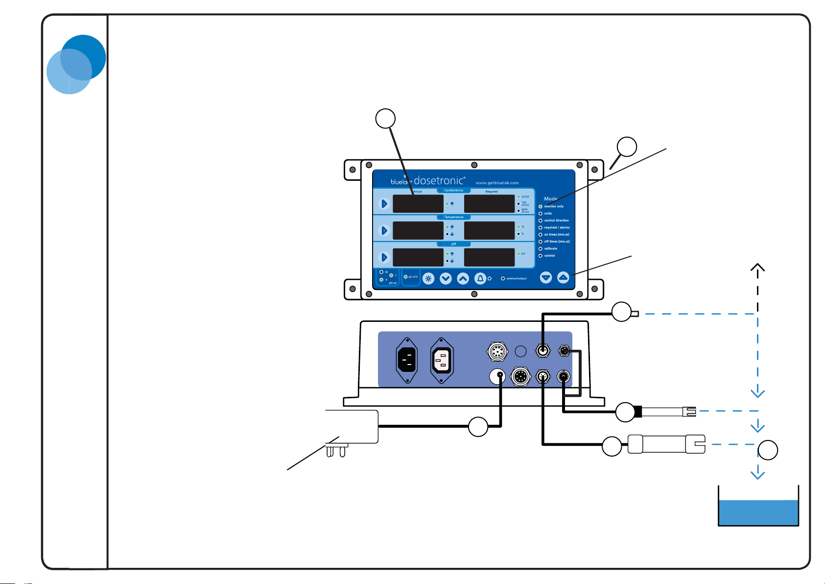
1.1 Quick Guide
This page shows a quick guide
to setting up the Dosetronic in
monitor mode. It serves as a quick
way to check that the controller is
operational.
1. Prior to mounting, attach
the Temperature, pH and
Conductivity probe to
Dosetronic unit.
2. Plug in power adaptor.
3. Place probes in solution.
4. Wait a few minutes for readings
to stabilise.
5
Monitor mode
WaterAir
pH probe
2.4
2.7
2.1
28
5.65.6
5.9
2.4
2.1
1
Menu change
Temperature probe
2
Power adaptor
2
3
2
Conductivity probe
Version S1.3 : 260511
1
4
Bluelab Dosetronic Solenoid Kit
Page 6
1
ct
y
Bluelab Corporation Limited
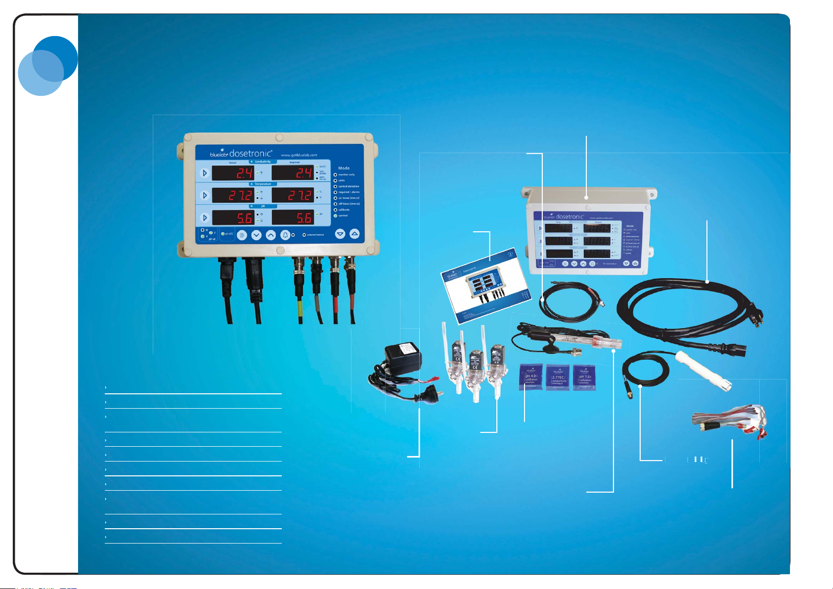
1.2 Dosetronic Kit Contents
Bluelab Dosetronic
Controller
Power Supply
Temperature Power in and Power out cables
(country specific)
pH probe
Conductivity Probe
Temperature Probe
3 x 24VAC Solenoids with power supply and leads
pH 7.0, pH 4.0 and EC 2.77 single use Solution
Sachets
Instruction manual
OPTIONAL: Alarm box, pH probe with ATC
®
Solenoid kit
Solenoid
power supply
Instruction
Manual
3 x 24VAC
Solenoids
Temperature
Probe
pH 7.0, pH 4.0,
EC 2.77 single use
solution sachets
Bluelab pH probe
(standard probe
supplied)
Dosetronic controller
Power Supply
Temperature in &
out power cables
(country specific)
Conductivity
Probe
Solenoid
Connector leads
Bluelab Dosetronic Solenoid Kit
2
2
Version S1.3 : 260511
Page 7
1
Bluelab Corporation Limited
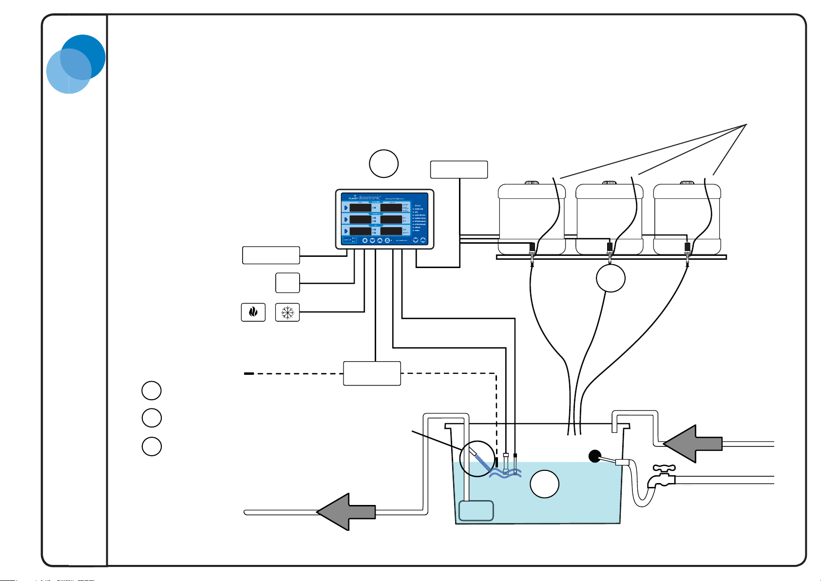
1.3 System Overview
It is useful to plan
where the labelled components
will be situated before beginning
installation of the system. Generally
the components are installed in this
order.
Dosetronic
Power
Power 5V DC
Alarm
Heat / Cool device
Setup Order
Nutrient Tank
1
(measuring air) (measuring water)
3
Temperature
probe
Solenoid
Power
Power 24V AC
pH probe
Conductivity probe
Stock Solutions
Nutrient BNutrient A
2
pH
(lower or raise)
Breather Tubes
Stock Solution
2
Dosetonic Controller
3
Nutrient agitator/mixer
1
To Crop
* Your temperature probe needs to be in the medium you are controlling for example if you are
controlling air temperature, your probe needs to be in the air you are trying to control.
Crop return
Fresh water in
3
Version S1.3 : 260511
Bluelab Dosetronic Solenoid Kit
Page 8
1
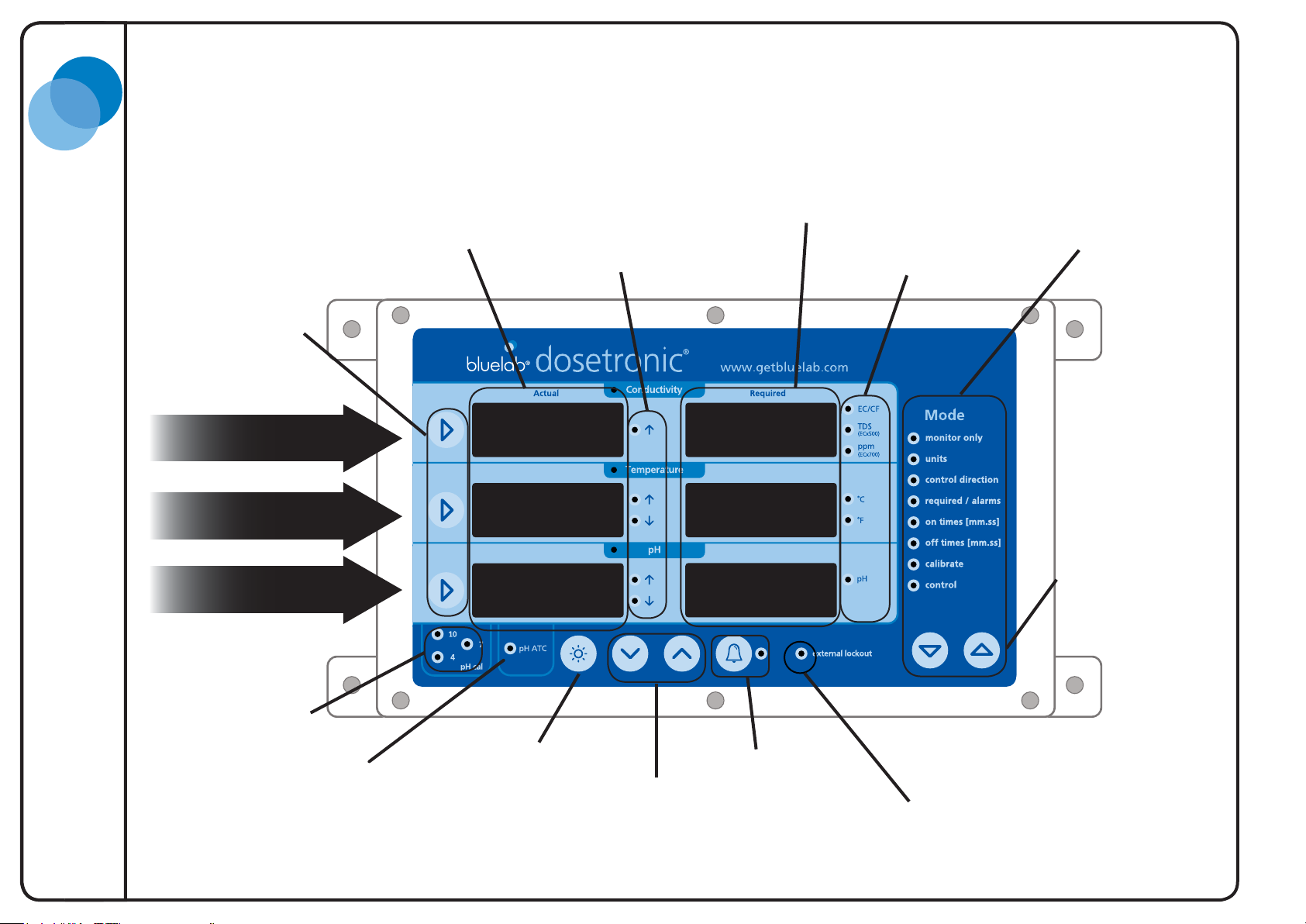
1.4 Dosetronic Control Panel
Actual readings
Measurement
Selection
Bluelab Corporation Limited
Required readings
Mode selection menu
Control direction Units
Bluelab Dosetronic Solenoid Kit
Conductivity
Temperature
pH
pH calibration
indicators
pH ATC
Automatic
Temperature
Compensation
1.2
18
6.5
Display brightness
increase/decrease
Value
1.3
16
6.8
Alarm &
Alarm indicator
Mode selection
keys
External lockout
indicator
4
Version S1.3 : 260511
Page 9
Power
pH
Dosing system
TemperatureConductivity
pH ATC
Alarm
Power Input
DC INPUT: 5V --- 3A
Temperature
Power Out
Temperature
Power In
1
Bluelab Corporation Limited
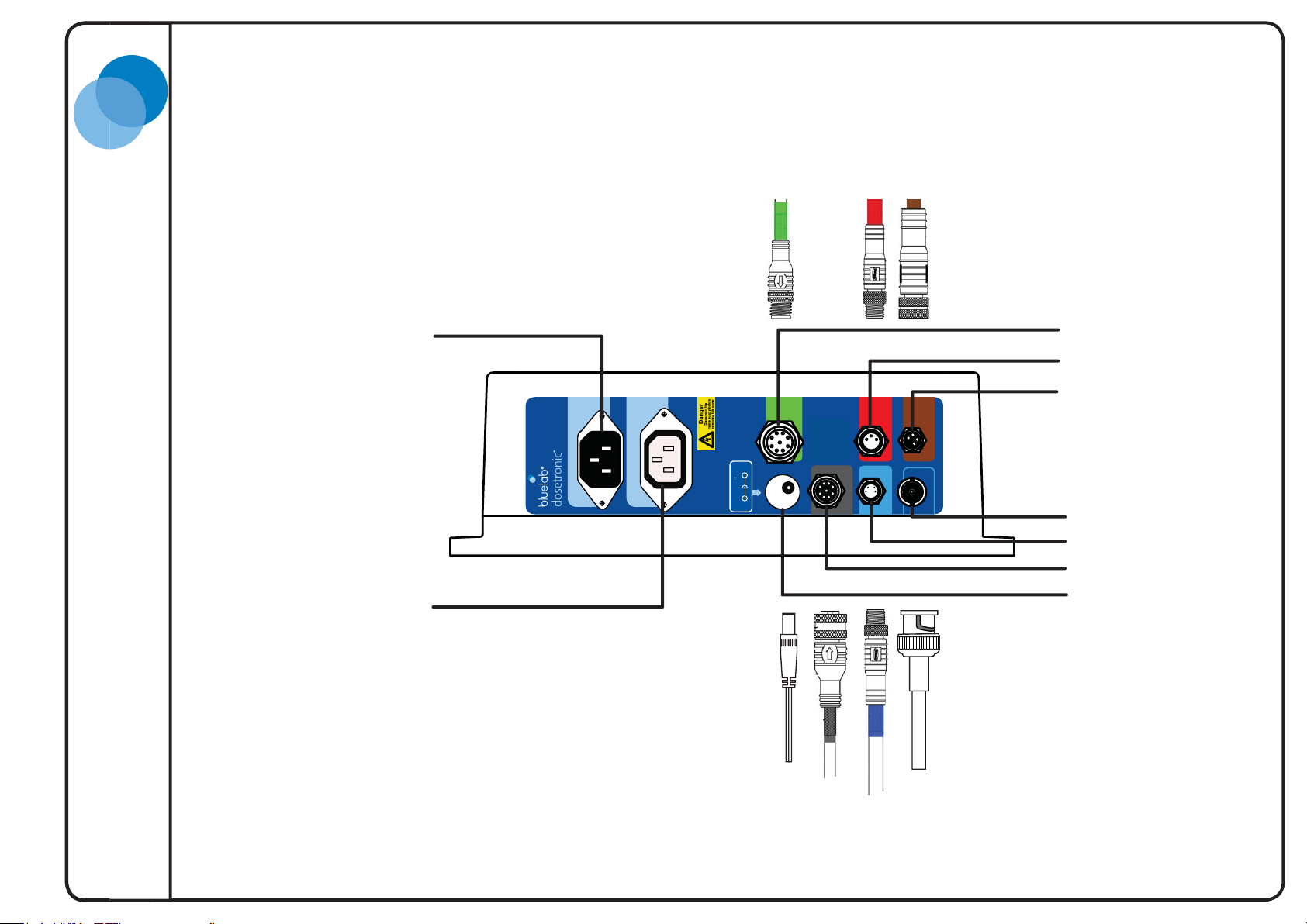
1.5 Dosetronic Connection Panel
Temperature
control
power in
Temperature
control
power out
Note: When inserting connector,
rotate to ensure it mates correctly.
Do not force it or you may bend/
damage pins. Fasten locking ring if
applicable.
Alarm & external
lockout box (optional)
Temperature probe
pH ATC (optional)
pH probe
Conductivity probe
Solenoids
Main power
5
Version S1.3 : 260511
Bluelab Dosetronic Solenoid Kit
Page 10

Bluelab Corporation Limited
Bluelab Dosetronic Solenoid Kit
6
Version S1.3 : 260511
Page 11

p
2
Bluelab Corporation Limited
Dosetronic System Installation and Wiring
2.1 Overview
To effectively set up the Dosetronic system you
must plan for where all the components of the
system will be placed. It will be helpful to refer
to the larger picture of the System overview on
page 3.
This section highlights the steps in chronological
order you need to take for installation of the
Dosetronic Solenoid kit.
Please read through this section and sketch a
rough system layout on the opposite page before
installation.
2.2 Nutrient Tank Set-up
The nutrient tank requires a constant water level.
Water regulators such as a plastic ball cock or
float switch are necessary.
For large tanks, mixing and/or aeration systems
are required. If there is no mixing system in
smaller tanks, stock solutions should be fed in
where the crop return and fresh water enters the
tank.
To Crop
solenoid tubing
Note:
Probes can be
submerged
Maximum
Pump
um
distance
Nutrient tank with submersible
pump
Crop return
fresh water in
Nutrient A & B must
not mix before entering
the water or else
precipitation will occur.
Also, do not place tubing
into the water or the
nutrient will not be able
to flow into the tank
7
Version S1.3 : 260511
Bluelab Dosetronic Solenoid Kit
Page 12
2
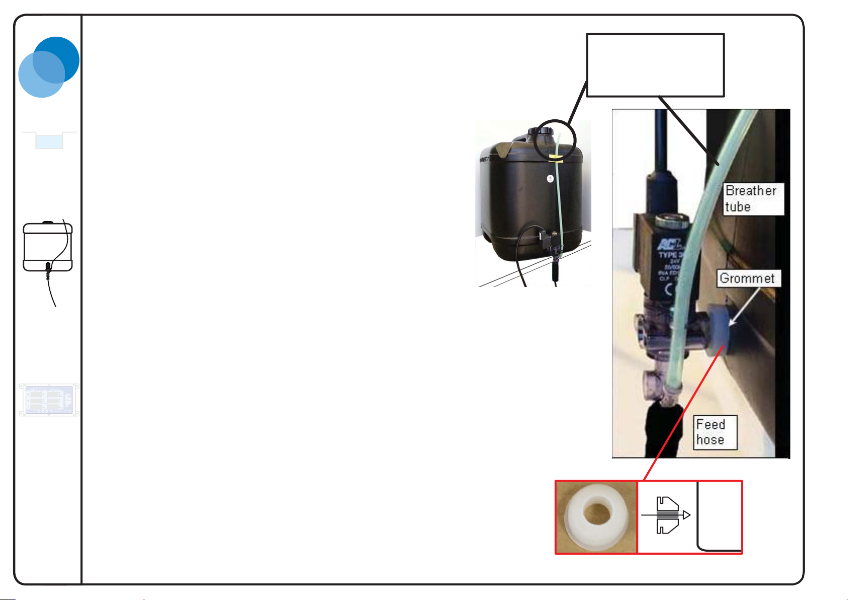
2.3 Stock Solution Location
The solenoids rely on gravity to deliver nutrient and pH adjuster
into the nutrient tank. This means the stock solution tanks must be
above the nutrient mixing tank.
Align stock tanks above nutrient tank.
2.4 Solenoid System Set-up
The solenoids dose nutrient and pH adjuster to your tank at defined
intervals. These intervals are set in the on times and off times
found in the mode menu. The instructions for this are on page 23
and 24.
Bluelab Corporation Limited
Breather tube must be
higher than the nutrient
level inside the stock
solution tanks.
Bluelab Dosetronic Solenoid Kit
1. Drill a 18mm (3/4”) diameter hole near the bottom of each stock
tank. Ensure tank is empty before drilling. Remove drilling
residue (swarf) from the inside of the stock tank as this can clog
the solenoids.
2. Insert sealing grommet. Seal must be tight, a firm push
is required. See figure 1.
3. Insert the solenoids into the grommets.
4. Label tanks Nutrient A, Nutrient B and pH.
5. Secure breather tube to the top of the stock tank to avoid
spillage.
6. Place the feed hoses from the solenoids to the main tank.
To ensure even dosing of Nutrient A & B the tubes have to be
the same length. Nutrient A & B must drop into the tank, do
not mix before entering the water.
7. Test stock tanks for water tightness. Fill with nutrient or pH
adjust solution.
To prevent acid
damage on your
piping & fi ttings,
make sure you dilute
your acid solution to
5% or less.
To gain greater control
of conductivity, mix
nutrient A and B as per
nutrient manufacturers
instructions.
Figure 1 - sealing grommet
Tank
8
Version S1.3 : 260511
Page 13
2
Nutrient BNutrient A
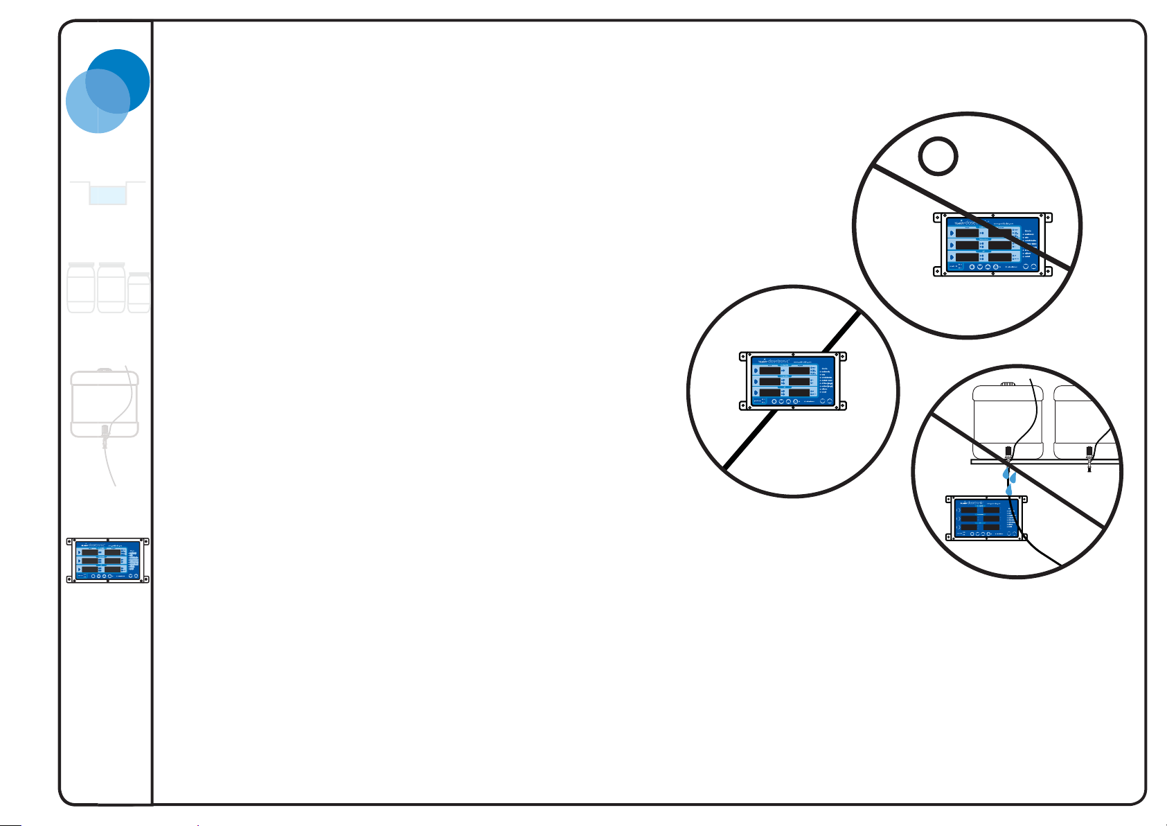
2.5 Mount Dosetronic Control Case
The Dosetronic has an indoor, splash-proof case and should
be installed in close proximity to your system.
Steps
1. Locate area
Find appropriate flat vertical surface to mount Doestronic
controller.
The Dosetronic controller cables need to be within reach of the
solenoids, nutrient tank and power outlet.
2. Secure Controller
Avoid mounting near electrical
mains and other
powered devices
Bluelab Corporation Limited
I
I
I
I
I
I
I
I
I
I
I
I
I
I
I
I
I
I
Keep Dosetronic out of
direct sunlight
Secure Dosetronic to the wall with the fasteners provided.
DO NOT mount the Dosetronic below the
nutrient tanks. Possible leakage from
the tanks could damage the controller.
9
Version S1.3 : 260511
Bluelab Dosetronic Solenoid Kit
Page 14
Bluelab Corporation Limited
Power
pH
Dosing system
TemperatureConductivity
pH ATC
Alarm
Power Input
DC INPUT: 5V --- 3A
Temperature
Power Out
Temperature
Power In
2
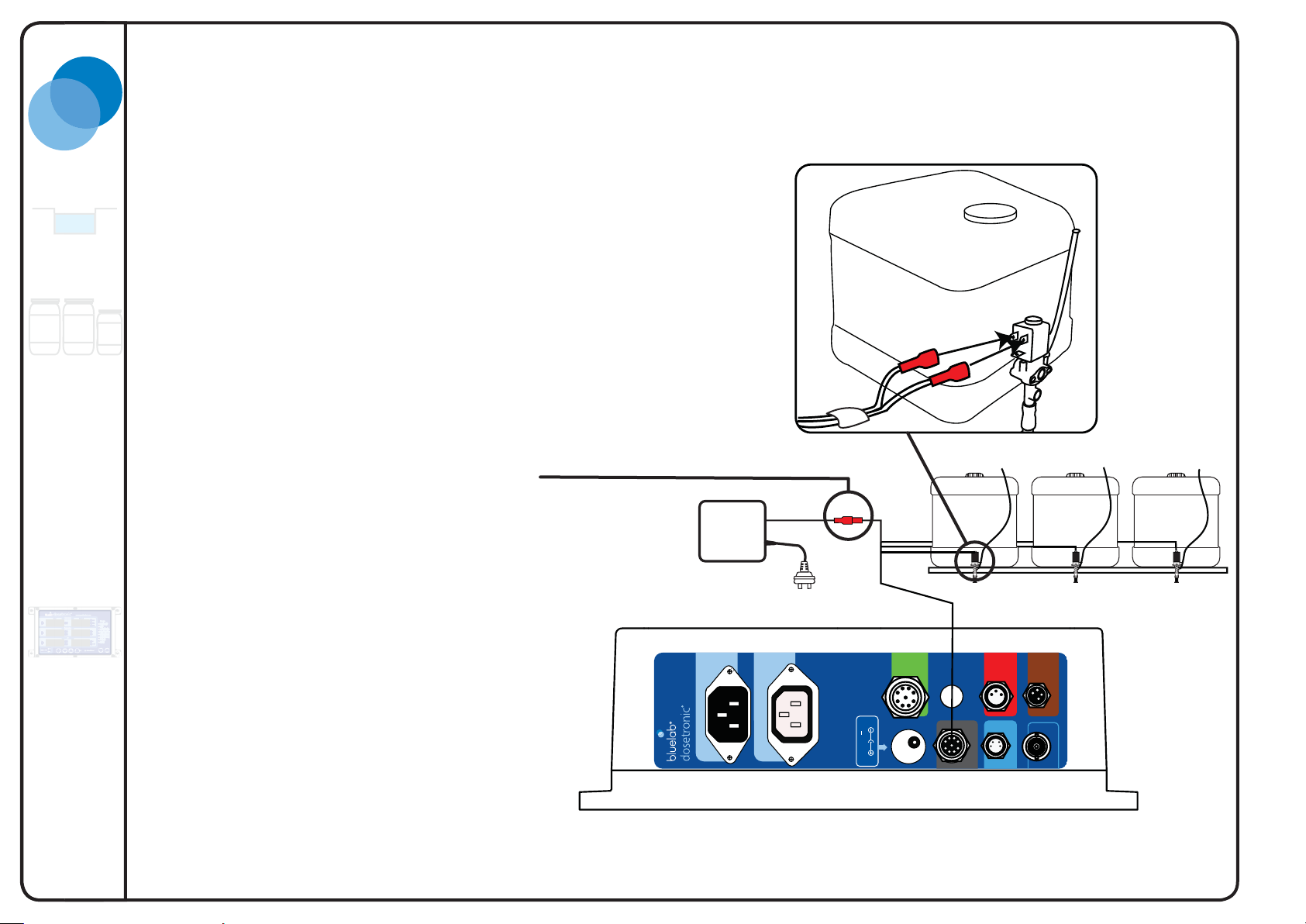
2.6 Solenoid Connection
Steps
1. Plug main solenoid lead into Dosetronic case.
2. Each pair of connectors is labelled for identifi cation.
3. The main lead has three leads that branch from
it. Each lead has two plugs, attach both of these
to the top two connectors of each solenoid. There
is no connector for the bottom terminal (polarity
is not important).
4. Connect the solenoid power source
(24V AC) to the solenoid leads.
Run lead sets from the solenoids
around the back of the stock
solution tanks as pictured
Power
24V AC
Attach eachv lead with two
plugs to solenoid
A
A
Nutrient A
Nutrient B
pH
(lower or raise)
Bluelab Dosetronic Solenoid Kit
10
Version S1.3 : 260511
Page 15

t
Temp
n
Temp
Out
f
y:
C
d
e
au
o
dus
a
a
k
g
0
e
ea
a
d
p
2
Bluelab Corporation Limited
pH ATC
(optional)
2.7 Probe connection and placement
Probes need to be placed close together
in the nutrient tank near where there
is good mixing. This could be near an
agitation jet or a water inlet valve. They
need to be as far away as they can be
from any submersed pumps (this will
minimise interference to your reading)
and away from where the nutrient and
pH solution falls into the tank.
Power I
pH and pH ATC (optional)
The Dosetronic Solenoid kit has a
standard pH probe. For a more accurate
pH measurement a pH ATC probe can be
purchased. It connects to two separate
sockets. The sockets are labelled pH
and pH ATC. Together they provide a
temperature compensated reading that is
more accurate than a standard pH probe.
orporation Limite
actured in New Zealand b
anu
Whiore Av
Bluelab
r
l P
tri
n
l
a 314
In
rik
w Z
T
Tauran
N
Temperature
Conductivity
erature
erature
wer
Power Inpu
Temperature
Conductivity
pH
pH
Temperature Probe
Crop return
The temperature probe can measure the
temperature of either water or air.
The temperature probe must be
measuring what your Dosetronic is
controlling (air temperature or water
To Crop
Pump
um
Your probes need to
be as far as possible
from any submersible pumps
and where nutrient and
pH solutions enter the tank
fresh water in
temperature).
Version S1.3 : 260511
11
Bluelab Dosetronic Solenoid Kit
Page 16

2
Power
pH
Dosing system
TemperatureConductivity
pH ATC
Alarm
Power Input
DC INPUT: 5V --- 3A
Temperature
Power Out
Temperature
Power In
2.8 Temperature Adjustment
The Dosetronic can control either air or
water temperature via an external heater/
cooler.
These sockets allow the Dosetronic to
switch the heater or cooler on and off.
The heater/cooler works at defined
intervals. These intervals can be
programmed in the “On” and “Off Times”
found in the Mode menu. Instructions for
this can be found on page 23 and 24.
Temperature
Power In
Bluelab Corporation Limited
Temperature
Power Out
Bluelab Dosetronic Solenoid Kit
Note: Do not connect the “Temperature
Power In” to a power source until you
have programmed the Dosetronic
Controller.
Temperature Power In
This socket provides external power for
the heater or cooler.
Temperature Power Out
This socket is where you plug in a heater
or cooler.
Note: You must place temperature
probe in or near what you are
controlling
Temperature
Power In
Or
Temperature
Power Out
12
Version S1.3 : 260511
Page 17

Bluelab Corporation Limited
pH
Dosing system
TemperatureConductivity
pH ATC
Alarm
Power Input
DC INPUT: 5V --- 3A
Temperature
Power Out
Temperature
Power In
2
2.9 External Alarm
and Lockout Box
(optional)
The alarm box has three functions:
1. It has an Internal alarm that sounds when a
designated alarm setting has been breached. This
feature can be enabled/disabled manually by opening
up the alarm casing and switching the link. (see
diagram on next page).
2. It can also be connected to an alternative external
alarm e.g. a fl ashing light or a horn. This can be done
through the external alarm wiring terminals provided
(see diagram on the next page).
3. It has an External Lockout function. When an external
lockout function is sensed in control mode (e.g.
through a water fl ow switch) the Dosetronic will stop
all control and dosing. The external lockout terminal
can be accessed on the circuit board found inside the
alarm box (See diagram on the next page).
Not supplied with this kit as standard
Alarm Box
Note: If no functions provided by the
Alarm Box are required, it does not need
to be installed/connected.
Mounting points
External Alarm
External Alarm and Lockout
2.10 Mount External Alarm Box
(optional)
1. Locate appropriate area on the
wall for the Alarm box.
2. Secure box to wall with self
tapping fasteners provided.
External Lockout
Sensor
13
Version S1.3 : 260511
Bluelab Dosetronic Solenoid Kit
Page 18

2
Bluelab Corporation Limited
2.11 Alarm Box Internal Overview (optional)
Internal alarm
DIS / ENA
*
EXT
ALARM
COM
NC
LOCKOUT
NO
Disable / Enable link
for internal alarm
External alarm
terminals
A factory installed link is across
NC (normally closed) terminals.
Remove when installing any NC
switches.
Common
Normally closed
Normally open
External
lockout
terminals
Bluelab Dosetronic Solenoid Kit
14
Version S1.3 : 260511
Page 19

Bluelab Corporation Limited
2
2.12 Wiring Alarm and External Lockout
(optional)
External alarm
To connect an external alarm to your system,
put a wire on each side of the closing contacts
marked EXT ALARM.
Note: The external alarm needs to have an
independent power source.
External lockout
To enable the external lockout function on your
Dosetronic, a switch needs to be connected to
the external lockout wiring terminal on the alarm
circuit board (see diagram on page 14). There
are two types of switches that can be wired in:
those that are normally open and those that are
normally closed.
We Supply
Refer to specifications for
maximum power rating
Common
Normally Closed
Normally Open
Note: You can have both NC and NO combinations connected
You Supply
- +
EXT ALARM
For example: If you connect a flow switch (that
opens when water stops flowing) to the normally
closed port, the external lockout function will
sense that the water has stopped and stop your
system from dosing.
Note: If you are not using any NC switches in
your system, ensure factory link is installed.
COM
NC
NO
COM
NC
NO
Series
Parallel
Connect multiple normally
closed switches in series
Connect multiple normally
open switches in parallel
15
Version S1.3 : 260511
Bluelab Dosetronic Solenoid Kit
Page 20

Bluelab Corporation Limited
Power
pH
Dosing system
TemperatureConductivity
pH ATC
Alarm
Power Input
DC INPUT: 5V --- 3A
Temperature
Power Out
Temperature
Power In
2
Main Power
2.13 Main Power
Once you have set up your system, connect it to the
power supply. The following chapter will explain how to
program your controller.
1. Select appropriate plug adaptor for your country.
2. Connect the mains plug adaptor to the power
supply. Ensure it is pushed fully on and locked into
place.
Bluelab Dosetronic Solenoid Kit
16
Version S1.3 : 260511
Page 21

3
Display Setup
3.1 Overview
Controller modes
Can be selected using the direction
keys in the mode selection menu.
Measurement selection
There are three measurements:
conductivity, temperature and pH.
These can be selected using the
measurement selection arrow keys.
Measurement selection
arrow keys
1.2
Bluelab Corporation Limited
Mode selection menu
1.3
Value increase/decrease
Value adjustments can be made
by the increase/decrease buttons
when in the appropriate mode.
18
6.5
Value
Increase/decrease
keys
16
6.8
17
Version S1.3 : 260511
Bluelab Dosetronic Solenoid Kit
Page 22

33
3.2 Monitor only mode
Monitor mode only shows the readings
from your conductivity, temperature and
pH probes. No control action
occurs.
Press mode up and down keys to select.
Bluelab Corporation Limited
2.7
23
Alarm Function
To turn the alarm on or off press this
key. If it is activated the indicator next to
the button will be lit. It can be changed
during any mode.
8.8.8.8.
br 8
6.3
Brightness Control
1. Press and hold down the
brightness button.
2. Adjust brightness using
increase/decrease buttons.
This can be done at any time.
2
External lockout
This indicator is lit whenever a
“lockout” condition is sensed through
the alarm box. If sensed (the alarm box
is plugged in with sensors connected)
all control activity will be stopped (see
Page 13 & 15).
Bluelab Dosetronic Solenoid Kit
1
18
Version S1.3 : 260511
Page 23

33
Bluelab Corporation Limited
3.3 Units mode
1. Select units
Press up and down keys to
select mode.
2. Select desired
measurement to change by
pressing its arrow key.
3. Switch between units
Use the value increase/
decrease keys to switch
to your desired units of
measurement.
Note: The EC/CF indicator
has two units for one
LED. To change between
the two, press the value
key twice. The difference
between the two is that EC
has a decimal place, where
CF does not.
2
Units
2.7
23
3
Note: pH has no selectable units
EC/CF
indicator
1
19
Version S1.3 : 260511
Bluelab Dosetronic Solenoid Kit
Page 24

3
Bluelab Corporation Limited
3.4 Control direction mode
Control direction lets you specify
in what direction you want the
Dosetronic to adjust your system.
1. Select control direction
Press up and down keys to select
mode.
2. Select desired measurement to
change by pressing its arrow key.
3. Switch between units
Use the value increase/decrease
keys to change your control direction.
23
6.3
Control direction
Off
1
Mode
selection
keys
Bluelab Dosetronic Solenoid Kit
Measurement
selection keys
Conductivity: Raise only or off
Temperature: Raise or lower or off
pH: Raise or lower or off
2
3
Value increase/decrease
keys
20
Version S1.3 : 260511
Page 25

3
Ala
i
d
Ala
o
w
Bluelab Corporation Limited
Please record
your values
here for future
reference.
Nutrient
Alarm High
Required
Alarm Low
Temperature
Alarm High
Start Stop
Alarm Low
3.5 Required / Alarms mode
Required/Alarms lets you set the values
you require the Dosetronic to maintain.
It also lets you set a high alarm and
a low alarm value so the system can
notify you if these are exceeded.
1. Select required/alarms
Press up and down keys to select mode.
2. Select measurement to change
To edit values press the appropriate
measurement button and press the same
button again to toggle between settings
for this measurement.
Note: See following page for how to set
the temperature values.
3. Edit alarm and required values
Use the value increase/decrease buttons
to change the value you have selected.
Alarm Hi
r
H
Required
q
ire
Alarm Low
r
L
Alarm “Quick-set”
2
AL.H1
rd
AL.LO
Note: Selected value will
be brighter than other
values displayed.
2.12.1
1.5
0.8
3
Alarm Low
1
Alarm Hi
pH
Alarm High
Required
Alarm Low
Note: If the values you are
changing in required reach that
of Alarm High or Alarm Low
they will “bump” these values
so they don’t overlap.
This allows you to quickly
set the “alarm HIGH” and
“alarm LOW” values for all
of the three measurements.
The alarm values are taken
from the actual readings.
The table below shows the
values that are present when
“quick-set” is used.
Conductivity
Temperature
pH
Actual value -2CF / 0.2EC
100 TDS
140 ppm
Actual value -3°C / 5°F
Actual value --
Actual value +
2CF / 0.2EC
100 TDS
140 ppm
Actual value +
3°C / 5°F
Actual value +
21
Version S1.3 : 260511
Bluelab Dosetronic Solenoid Kit
Page 26

Temperature Required /
Alarms
Bluelab Corporation Limited
Temperature control works slightly
different from conductivity and pH.
This is because temperature is hard
to maintain constantly. For example
if you are heating your greenhouse
the “temperature on” value will turn
on the heater and “temperature off”
will turn the heater off when these
temperature values are sensed.
Temperature Control O
If using a
Temperature Raise / Heating Device
Temperature Control On
Alarm High
Temperature on
Alarm Low
26°C
24°C
AL.H1
AL.LO
30
2624 26
Temperature off
22
Note:
It is normal practice to set your temperature
on time to continuous. The following page
shows you how to do this. This allows
the heater/cooler to operate until the
temperature off value is reached.
Bluelab Dosetronic Solenoid Kit
If using a
Temperature Lower / Cooling Device
Temperature Control O
22
Version S1.3 : 260511
Page 27

3
Bluelab Corporation Limited
3.6 On Times
Please record
your values
here for future
reference.
Nutrient
On times
Temperature
On times
pH
On times
On times are how long you dose
for. Together with the “Off Times”
this allows the Dosetronic to make
small frequent changes to the
conductivity, pH and temperature
of your system.
Adjust on time so that 3+ doses
changes the actual value by 1 digit.
Adjust off time (following page) to a
little longer than the time it takes for
a dose to be mixed and the change
sensed by the probes.
1. Select On times
Press up and down keys to select
mode.
2. Select desired measurement and
value to change
To programme On Times select the
appropriate measurement.
Note: Selected value will be
brighter than other values
displayed.
3. Programme desired On Times
Press (or hold down) the value
increase/decrease buttons
to change the value you have
selected.
2
Note: Start with short on times and
adjust from there.
Note:
Continuous Mode
This allows you to set your nutrient pumps,
pH adjuster and/or heater/cooler to
work continuously until the values reach
the required reading. This is helpful for
temperature regulation when you want the
heater/cooler to start at one temperature
and run continuously until off temperature is
reached.
cont
OO.O1
OO.53
3
1
Programmable from 0-10 minutes
in one second steps.
cont
23
Version S1.3 : 260511
Bluelab Dosetronic Solenoid Kit
Page 28

3
Bluelab Corporation Limited
3.7 O Times
Please record
your values
here for future
reference.
Nutrient
Off times
Temperature
Off times
pH
Off times
Off times are how long no dosing
will occur for. This gives your
system time to adjust/mix so
that the Dosetronic can measure
the changes it has made before
deciding if it needs to dose again.
1. Select Off Times
Press up and down keys to select
mode.
2. Select desired channel and
value to change
To programme Off Times select
the appropriate measurement.
Note: The selected value will
be brighter than other values
displayed.
3. Programme desired Off Times
Press (or hold down) the value
increase/decrease buttons
to change the value you have
selected.
2
59.50
59.50
1
59.50
3
Programmable from 0 - 59 minutes and 59
seconds in ten second steps
Bluelab Dosetronic Solenoid Kit
Note: Start with long off times and
adjust from here
24
Version S1.3 : 260511
Page 29

3
3.8 Calibration
Calibration is an essential part
of maintaining your probes.
It ensures your readings are
accurate and needs to be done
regularly.
1. Select Calibrate
Press up and down keys to select
mode.
Bluelab Corporation Limited
pH
CAL
3.9 pH Calibration
1. Rinse pH probe in fresh water
and place probe in pH 7.0
calibration solution and wait for
reading to stabilise. Press and
hold the measurement arrow
key and wait for pH cal to be
displayed. If the indicator turns
green proceed to step 2.
2. Rinse pH probe in fresh water
and place probe in pH 4.0 or pH
10.0 calibration solution and wait
for reading to stabilise. Press
and hold the pH button.
If you get Err displayed, check:
1) calibration solutions are correct
2) Probe is not damaged
3) Probe is connected correctly
If Err is still displayed then the probe needs replacing
2
Calibration Status
Using factory default calibration values.
pH 7 calibrated OK. Using factory default for
pH 4 and/or 10.
pH 7 & pH 4 calibrated OK.
Indicators flashing - 30 days have passed
since last full calibration. Calibration due.
7.0
= 7
pH probe evaluation
pH probes age over time. They should be
replaced at least once a year. Whenever you
calibrate your probe, an indicator will show the
health and tell you if you need to replace the
probe.
= 7
= 7
_ 7
Err
Excellent
OK
Poor
Replace
1
25
Version S1.3 : 260511
Bluelab Dosetronic Solenoid Kit
Page 30

3
3.10 Conductivity Calibration
Conductivity calibration is not generally
required. If you do notice that your
readings are not accurate, the first thing
you should do is clean your probes.
If readings are still inaccurate the
conductivity probe can be calibrated using
a known nutrient solution of 2.77EC (see
chart for corresponding units)
1. Place conductivity probe in
conductivity standard solution.
2
2.3
Bluelab Corporation Limited
-5
Bluelab Dosetronic Solenoid Kit
2. Calibrate Conductivity
Select Conductivity measurement.
3. Conductivity adjustment
Adjust until actual value is 2.8EC (or
chosen unit) by using
increase / decrease keys.
Solution
Value
Displayed
Value
3
Calibration Values
EC CF ppm 500 ppm 700
(TDS) (EC x 700)
2.77 27.7 1385 1939
2.8 28 1400 1960
26
Version S1.3 : 260511
Page 31

3
Bluelab Corporation Limited
3.11 Control
Control mode monitors your
Actual readings and adjusts them
to the Required values you have
programmed in the Required/
alarms mode. It does this through
the dosing systems installed.
Note: It is advised that you go
through “Preparing system to
run” in the next chapter before
setting the system in control
mode.
1. Select Control
Press up and down keys to
select mode.
2. Controller will adjust nutrient,
pH and temperature levels
accordingly.
When the system is dosing and
the values are being adjusted
the control direction indicator
lights will flash.
Actual Required
0.1
18
18
6.5
1.3
16
6.8
Note: If an actual value is flashing
in control mode and your dosing
system is not dosing it may be
because the value is outside of
the control range. This can be
changed by manually increasing
your nutrient levels in the stock
tank. For more information see the
troubleshooting section.
1
27
Version S1.3 : 260511
Bluelab Dosetronic Solenoid Kit
Page 32

Bluelab Corporation Limited
Bluelab Dosetronic Solenoid Kit
28
Version S1.3 : 260511
Page 33

4
Bluelab Corporation Limited
Preparing System to Run
Setting up the Dosetronic system involves setting the Control direction, Required values and On and Off times. These settings
can be edited by scrolling through the Mode menu on the Dosetronic Control panel. The steps for this are outlined in chapter 3.
4.1 Prepare the Dosetronic system to run
Step 1. Flush out PVC shavings and glue residue
If your system has been installed it is important to fl ush out PVC shavings
(swarf) and any glue residue before growing commences. To do this fi ll your
nutrient tank and then fl ush all water from your system.
Step 2. Fill tanks A, B and pH with stock solutions.
Step 3. Manually prime tank
In order for the Dosetronic to adjust your main nutrient tank to your
programmed required values you need to manually prime the tank with nutrient.
By Raising the EC to above 0.1 the Dosetronic will be able to start dosing.
Dosing stops at 0.0 - 0.1EC to prevent dosing if the probe is out of solution.
(Instructions are on the following page)
Step 4. Check readings/settings
Make sure all your settings are working and that your readings are within your
required range by scrolling through the mode menu.
Step 5. Plug Solenoids into mains power.
Outlined on page 10
Step 6. Plug heater/cooler into mains power.
Outlined on page 12
Note: The pH probe must be
kept wet at all times. Ensure the
nutrient probe is clean and the pH
probe calibrated before starting
this task.
Final Checklist
Nutrient tank set-up
Stock solution
Dosing system
Control case
Probe connections
Heater/Cooler
Alarm Box (optional)
Main Power
Units
Control direction
Off Times
On Times
pH calibration
Check dosing
Step 7. Complete checklist opposite.
Step 8. Select Control in mode menu. System should be running.
Monitor system regularly for 24 hours to check On & Off times are correct and
control is stable.
29
Version S1.3 : 260511
Bluelab Dosetronic Solenoid Kit
Page 34

4
Bluelab Corporation Limited
4.2 Manual override Control
Manual control lets you dose or alter
temperature by holding down the
measurement you want to change and both
the mode selection keys.
1. Select monitor mode using the mode
selection keys.
2. Press and hold the measurement key you
want to change.
3. Press both mode keys (3+4) together and
release.
4. Continue to hold measurement key while
dosing and release key to stop.
2
1.2
18
18
6.5
1.3
16
6.8
1
3 4
Bluelab Dosetronic Solenoid Kit
30
Version S1.3 : 260511
Page 35

5
Maintenance
5.1 Conductivity probe cleaning
Over time, nutrient salts build up on the face of
the conductivity probe. This effects conductivity
readings so the face of the probe must to be cleaned
at least once a month.
1. Remove shroud by holding the body and pulling
away the shroud.
2. Using the Bluelab conductivity probe cleaner or an
unscented liquid scourer such as Jif or Sof t Scrub
place one or two drops onto the probe face.
1 2
3
33
Bluelab Corporation Limited
3. Using a finger or Bluelab chamois, rub firmly and
vigorously to clean probe face.
4. Check that water forms an even film across the
surface of the probe. If beading of water is present,
clean again. Beading indicates the presence of oil on
the probe surface. This effects readings.
5. Refit the shroud and test in 27.7 CF/ 2.77 EC
solution. If reading is out it can be edited in
calibration mode. See page 26 for calibration
information. Always clean probe before calibrating.
4
31
Version S1.3 : 260511
Bluelab Dosetronic Solenoid Kit
Page 36

5
5.2 pH probe cleaning
Over time, nutrient salts build up on the glassware of the
pH probe when it is in the sample pot. This can effect pH
readings so cleaning once a month is important. ALWAYS
CLEAN PRIOR TO CALIBRATING
1. Rinse pH probe tip under fresh water.
Bluelab Corporation Limited
1 2
2. Fill a small container with clean water and add a small
amount of Bluelab pH probe cleaner or mild detergent
(dishwashing liquid).
3. Gently stir the pH probe tip in the mixture. Ensure that you
do not “knock” the probe on the side of the container as
this may cause damage to the probe. Rinse well under fresh
running water to remove all traces of detergent mixture.
4. Only if the probe tip requires removal of sediment, gently
brush around the glassware with a few drops of Bluelab pH
probe cleaner or mild detergent (dishwashing liquid) and a
soft toothbrush. DO NOT pull out or touch the wick.
5. Rinse well under fresh running water to remove all traces of
the detergent mixture.
6. Calibrate probe. See pH calibration on page 25
3 4
5
Bluelab Dosetronic Solenoid Kit
32
Version S1.3 : 260511
Page 37

5
Mounted on piston Side view Top view
Bluelab Corporation Limited
5.3 Solenoid Cleaning
Ring Nut
1. Turn off the Dosetronic and solenoid power supplies at the
wall. Refer to system overview for their location.
2. Carefully remove the solenoid valve from the grommet in the
tank (empty your tank first!)
3. Undo the top ring nut on the valve. This should be hand tight,
but it may be necessary to use a pair of pliers if it is too tight,
as shown in Figure 1.
4. Take the black coil off the solenoid, as shown in Figure 2.
5. Undo the two screws on the solenoid as shown in Figure 3.
6. Carefully disassemble the solenoid valve as shown in
Figure 4. Be very careful not to lose the spring between the
piston and the cylinder. Remove the diaphragm gently – do
not use any sharp tools.
7. Clean the diaphram (Figure 5) using Jif or dishwashing
detergent and a toothbrush if necessary. Check the
diaphragm carefully for holes / splits or any other
damage.
Figure 1:
Remove ring nut
Figure 4: Solenoid valve disassembly and completely
Coil
Solenoid and actuator
separated
Valve
Figure 2:
Valve
disassembled parts
Figure 3:
Remove solenoid
screws
Figure 5:
Normal, undamaged diaphragm
33
Version S1.3 : 260511
Bluelab Dosetronic Solenoid Kit
Page 38

5
Bluelab Corporation Limited
8. Check that the piston and cylinder are clean and that the
piston slides in and out of the cylinder with minimal friction. If the
piston or cylinder are not clean, wash and dry both parts thoroughly.
If the piston and cylinder are not thoroughly dry before reassembly,
corrosion will occur and the solenoid valve will stop working.
9. Check the plastic body and flow restrictor for blockages and
clean thoroughly. To check the flow restrictor for blockages: cover the
side hole on the body (the part which has the grommet on it normally)
and run water through from the top of the body. Water should flow out
the bottom of the flow restrictor. If water does not flow through the flow
restrictor it should be cleaned carefully or replaced with a new Bluelab
flow restrictor.
Bluelab Dosetronic Solenoid Kit
10. Once all parts are dry, reassemble them in the order that you
disassembled them.
11. Filter the solution from the tank and clean the tank thoroughly then put
the solenoid valve back into the grommet on the tank. Make sure the
breather tube is taped up so that it is above the liquid level in the tank
when full.
12. Turn power to the Dosetronic and solenoids back on.
34
Version S1.3 : 260511
Page 39

6
Bluelab Corporation Limited
Trouble shooting
6.1 Overview
In general, if your actual readings are flashing there will be a problem with the measurement e.g ineffective control. If the required
reading is flashing then there will be a problem with the method of control e.g an actual value is outside one of the lockout values.
(see page 30 for more a detailed explanation)
Nutrient reading low Contaminated probe Clean Conductivity probe (see p.31)
pH reading inaccurate Contaminated probe Clean pH probe (see p.32). Replace probe if in doubt
Calibration has expired Calibrate pH probe (see p.25)
6.2 Error Messages
Err
----
Probe is disconnected or
sensor is damaged
EC or pH temperature is out of
range (0-50°C)
Ur
Or
Measurement is under range
Measurement is over range
Version S1.3 : 260511
35
Bluelab Dosetronic Solenoid Kit
Page 40

6.3 Error FAQ
Bluelab Corporation Limited
Actual values
- The probe is out of water.
- The EC value of your solution is below 0.2.
- Your alarm is enabled, the value has met or exceeded
the alarm threshold.
- The system has noted ineffective control. The value
hasn’t changed by 2 steps in 15 cycles
(1 cycle = on and off times combined)
Problems
The alarm high/low (actual value) for one
measurement flashes, but does not seem to be
locking out the intended control (required value)
A control seems to be locked out - shouldn’t the
actual display flash for that measurement?
Required Values
- The values you have is outside the internal
Lockout values.
Solutions
For a measurement to act as a reason for locking
out another control, its control direction must be
set to raise or lower.
No: it is the required value that fl ashes if the
control is locked out. The actual display fl ashes if
the measurement is in error, or is in a state that
it could be a cause for a lockout. (e.g ineffective
control, or alarm high)
Bluelab Dosetronic Solenoid Kit
A conductivity or pH control locks itself out (its
required display is flashing). How do I know if the
cause was “ineffective control”?
Lockout due to ineffective control is where the
actual Conductivity or pH value does not move
two resolution steps in the required direction
after 15 on/off cycles. To solve this, change the
on and/or off time, so that the system sees a
change of one resolution step after 3 cycles.
36
Version S1.3 : 260511
Page 41

7
Bluelab Corporation Limited
Speci cations
pH Conductivity Temperature
Medium measured
Displayable units
Range
Resolution
Accuracy
Temperature Compensation
Solution Solution Air or Solution
pH Scale
0.0 - 14.0 pH
0.1 pH
±0.1 pH
Yes Yes N/A
(If ATC pH probe is connected)
EC
CF
TDS (ECx500)
ppm (EC x700)
0.0 - 5.0 EC
0 - 50 CF
0 - 2500 TDS
0 - 3500 ppm
0.1 EC
1 CF
50 TDS
70 ppm
± 0.1 EC
± 1 CF
°C
°F
0 - 50 °C
32 - 122 °F
1 °C
1 °F
±1 °C
±1 °F
Calibration
One, Two or
Three point
Yes
Not Required
Version S1.3 : 260511
37
Bluelab Dosetronic Solenoid Kit
Page 42

Bluelab Corporation Limited
Bluelab Dosetronic Solenoid Kit
Switches numbered 1 - 24
Lockout Switches
All switches by default are shipped
switched on
Mains supply
Danger
Disconnect the
mains supply before
removing this cover
38
Version S1.3 : 260511
Page 43

Bluelab Corporation Limited
Lockout Switches
Warning: Before opening the cover ensure mains power is removed.
The Dosetronic controller has a series of internal switches numbered from 1 - 24. These can be accessed by unscrewing the back
panel of the controller (See page 36). They have been preset to lockout (stop control for) temperature, pH and conductivity when
any alarm condition has been sensed. These switches can be turned on/off to set lockout behaviour for any alarm condition.
The new switch confi guration will not take effect until the controller has been restarted. This can be done by disconnecting then
reapplying power.
For example if you wanted your heater/cooler to stop when the conductivity meets or exceeds the high alarm value you could turn
on switch number 9.
Alarms
Conductivity
Temperature
pH
Locks Out
Low
Alarm
High
Low
Alarm
High
Low
Alarm
High
To Stop
Conductivity
(Raise)
Switch on
2
3
3
4
5
6
7
To Stop
Temperature
(Heat & Cool)
Switch on
8
9
10
11
12
13
To Stop
pH
(Raise & Lower)
Switch on
14
15
16
18
19
20
39
Version S1.3 : 260511
Bluelab Dosetronic Solenoid Kit
Page 44

Thank you for choosing to buy a Bluelab Dosetronic®.
Please register your free 2 year guarantee.
To help us ensure you receive a prompt and effective service, please register your guarantee by
completing and returning the form to us, or you are welcome to register online.
Bluelab Corporation Limited
Go to
www.getbluelab.com
Bluelab Corporation Limited
8 Whiore Avenue
Tauriko Industrial Park
Tauranga 3110 New Zealand
Customer Care
Call the Bluelab Helpline
NZ: +64 7 578 0849
(Mon - Fri 8:00 to 5:30)
Bluelab Dosetronic Solenoid Kit
or visit the Bluelab website:
www.getbluelab.com
40
40
Version S1.3 : 260511
Page 45

Bluelab Corporation Limited
For Future
Reference
Attach your
receipt
or proof of
purchase here
make a note
of your serial
number
Bluelab Dosetronic® details
Date of Purchase
Serial Number
Personal Details
Title
Telephone
E-mail
House/
Flat No.
Street
2 Year Guarantee Registration Form
Place of Purchase
Initial Surname
House/
Flat Name
Town
Postcode
Country
41
Version S1.3 : 260511
Bluelab Dosetronic Solenoid Kit
 Loading...