

Page 1
Cleaning Instructions,
Replacing Pilot and
Control Valve
Series: GWU501E, GWU511A
Page 2
For assistance call: 1.800.762.1142
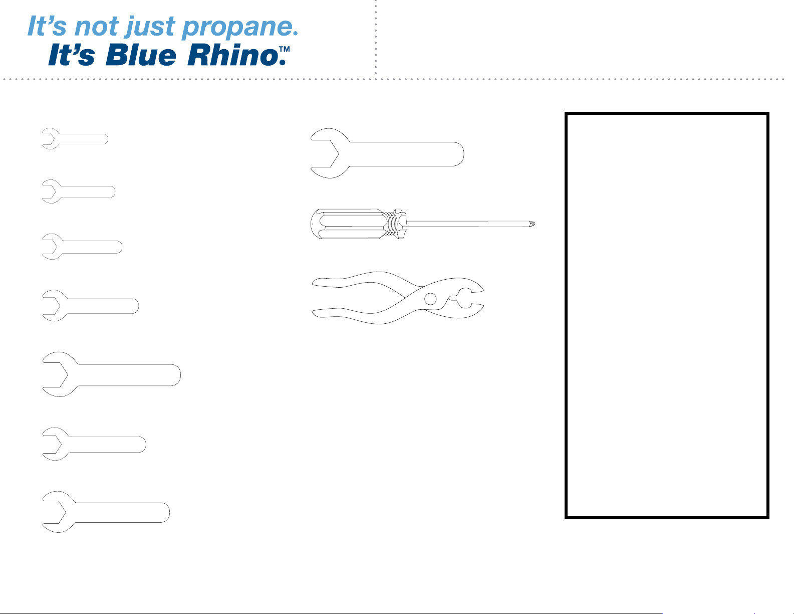
Tools Required for Assembly:
8 mm open end wrench
9 mm open end wrench
10 mm open end wrench
12 mm open end wrench
17 mm open end wrench
3/4” open end wrench
# 2 Phillips screw driver
Pliers
Compressed air – canned or
compressor with a hose
Soft bristle brush
1. Installation and repairs
should be done by
a qualified service
person.
2. Use only Blue Rhino Global
Sourcing, Inc. factory
authorized parts. The use
of any other part that is not
factory authorized can be
dangerous and will void
your warranty.
3. Do not use flammable
solutions or material to
clean heater or heater
1/2” open end wrench
5/8” open end wrench
Brass brush
Heavy-duty pipe cleaners
Non-abrasive Scouring Pad
Leak test solution: 1 part liquid soap
and 3 parts water
parts. Use only warm
soapy water to clean
outside of heater.
4. Do not submerge control
valve in water.
2Cleaning Instructions, Replacing Pilot and Control Valve • Series: GWU501E, GWU511A
Page 3
For assistance call: 1.800.762.1142
Step 1 – 6
1. For assistance call 1.800.762.1142 toll free. Please have your owner’s manual and model number available
for reference.
For Easiest Assembly:
• To avoid losing any small components or hardware, assemble your product on a level surface that does
not have cracks or openings.
• Clear an area large enough to layout all components and hardware and that is soft to not scratch or
damage any surface finishes.
• When applicable, tighten all hardware connections by hand first. Once the step is completed go back and
fully tighten all hardware while being cautious not to over tighten to avoid damaging surfaces or stripping
hardware.
• Follow all steps in order to properly assemble your product.
2. Turn off heater per “Turning Off” instructions in owner’s manual.
3. Disconnect LP gas tank per “Disconnect LP Gas Tank” instructions in owner’s manual.
4. Make sure heater is completely cool (at least 45 minutes after use) before proceeding.
5. Remove dome per instructions in owner’s manual.
6. Remove engine from post per instructions in owner’s manual.
3Cleaning Instructions, Replacing Pilot and Control Valve • Series: GWU501E, GWU511A
Page 4
For assistance call: 1.800.762.1142
Step 7
(1 shown)
1. Remove the emitter screen: there are 4 phillips head screws that hold the emitter screen (the section that gets hot)
to the emitter bottom. Remove these screws then remove the emitter screen. Set aside for later reinstallation.
2. Remove the control knob.
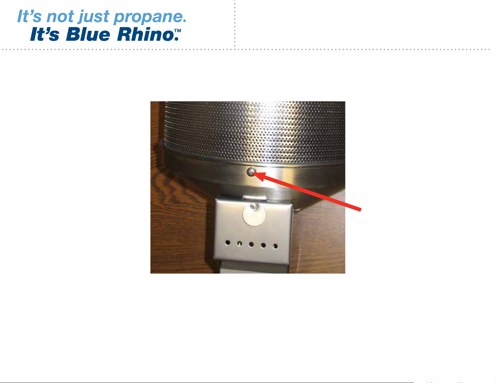
3. Remove the engine/emitter assembly front access panel by unscrewing the black thumb screw (located near the
post connection)
4. Disconnect the igniter wire from the igniter box.
4Cleaning Instructions, Replacing Pilot and Control Valve • Series: GWU501E, GWU511A
Page 5
For assistance call: 1.800.762.1142
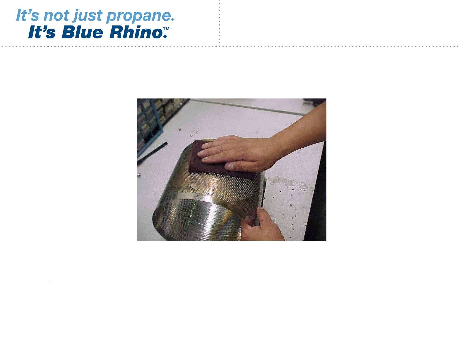
Step 8
Clean the carbon build-up off the inside of the emitter bottom with a non-abrasive scouring pad or bottle brush. Clean
the outside of the emitter bottom with the scouring pad.
DANGER: Never use any flammable solutions or material to clean heater or heater parts. Use only a mild soap
and water solution.
Do not to soak the valve.
5Cleaning Instructions, Replacing Pilot and Control Valve • Series: GWU501E, GWU511A
Page 6
For assistance call: 1.800.762.1142
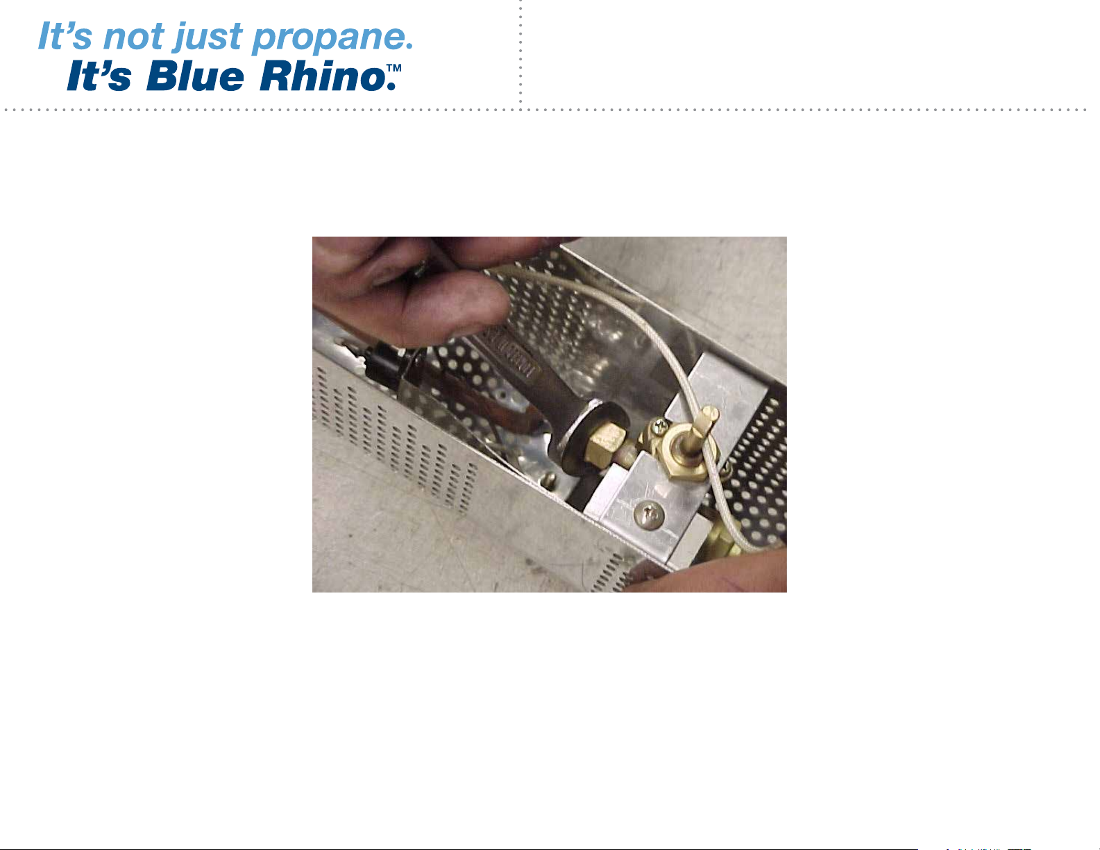
Step 9
To remove the burner, hold the burner supply tube nut in place with an # 10 mm open-end wrench to prevent it from
moving. At the same time, using another # 12 mm open-end wrench unscrew the burner nut from the burner. With the
nut loose, lift the burner out of the valve housing. Use care not to damage the supply tube or any of the wires for the
thermal-couple.
6Cleaning Instructions, Replacing Pilot and Control Valve • Series: GWU501E, GWU511A
Page 7
For assistance call: 1.800.762.1142
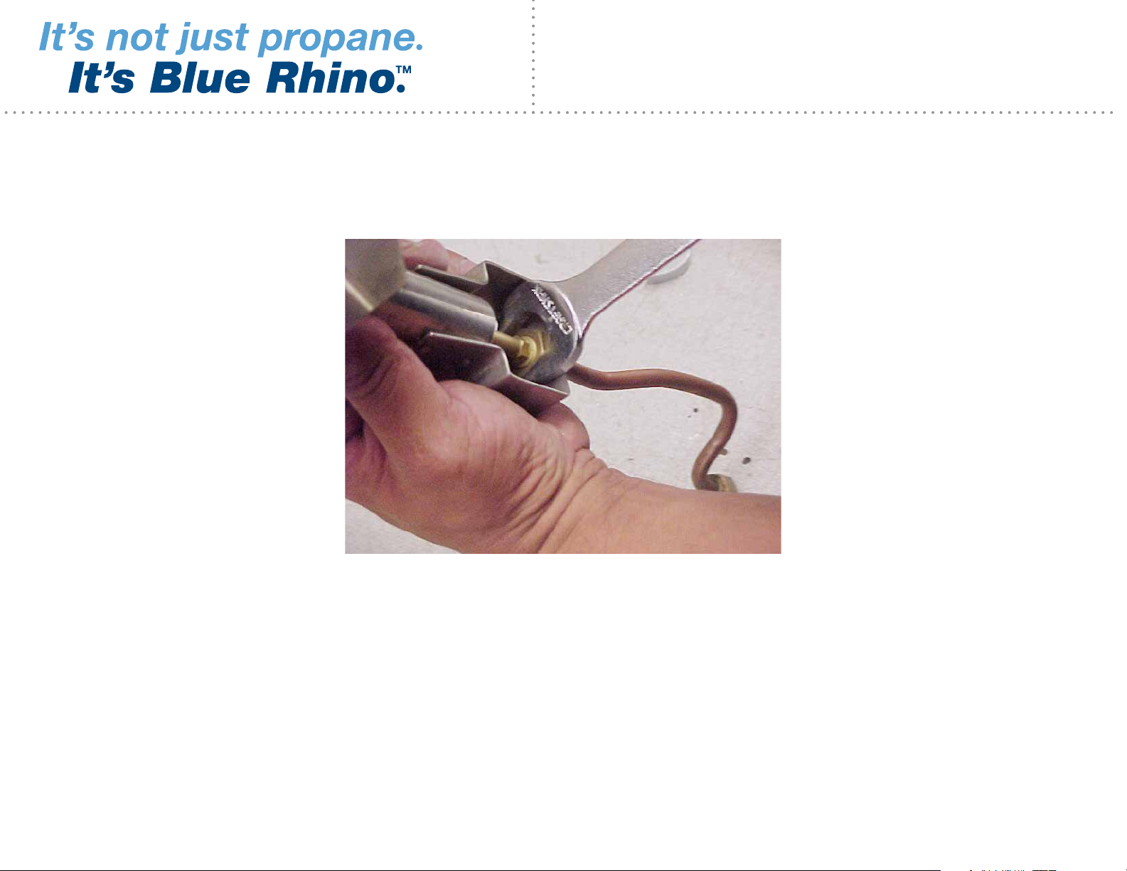
Step 10
To remove the burner supply tube, unscrew the brass nut which attaches the burner supply tube to the burner bracket.
Be careful not to damage the burner.
7Cleaning Instructions, Replacing Pilot and Control Valve • Series: GWU501E, GWU511A
Page 8
For assistance call: 1.800.762.1142
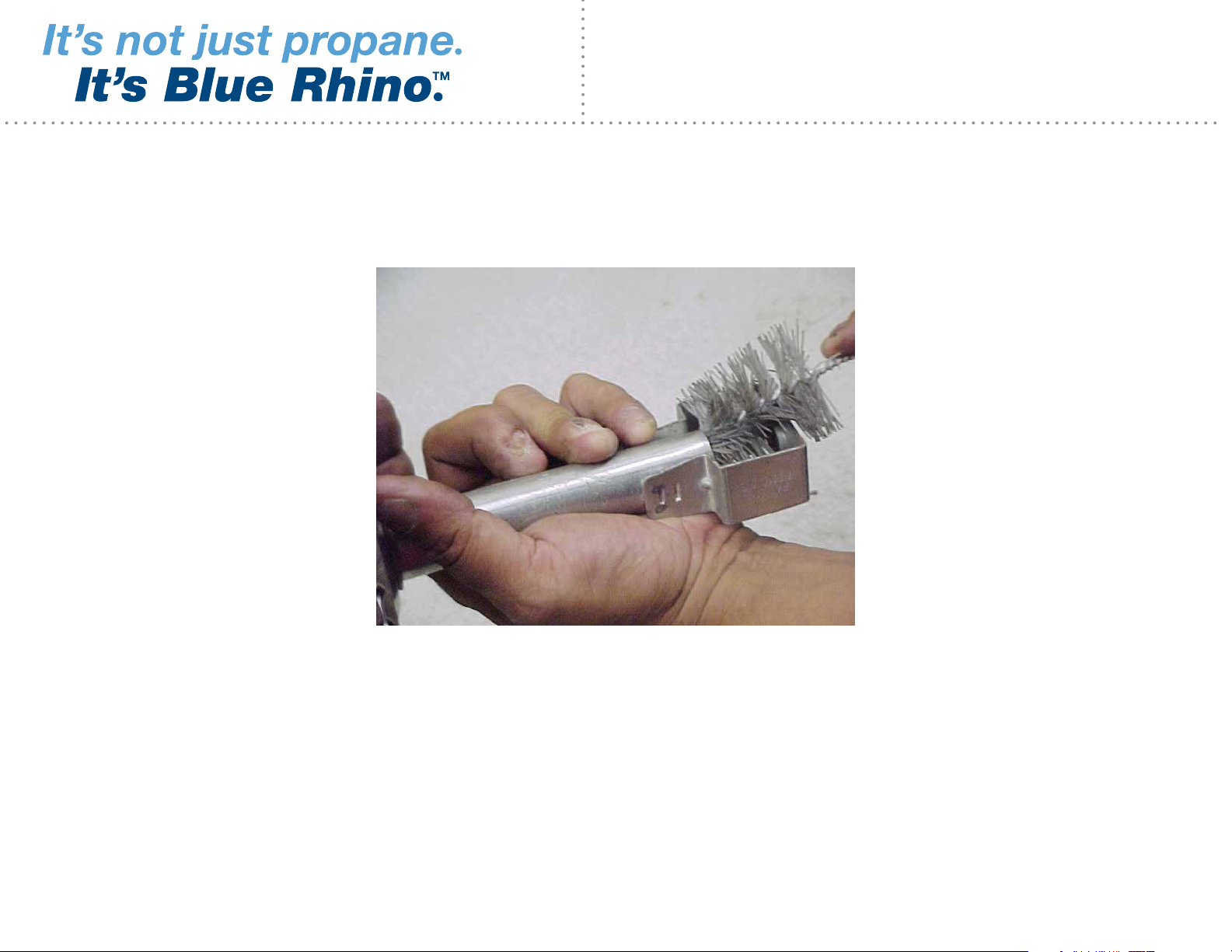
Step 11
Insert bottle brush into venturi tube and give a couple of twists. This will clear any debris or spider webs from the
venturi tube.
8Cleaning Instructions, Replacing Pilot and Control Valve • Series: GWU501E, GWU511A
Page 9

For assistance call: 1.800.762.1142
Step 12
Insert a heavy-duty pipe cleaner into each burner port to clean them. Use a non-abrasive scouring pad to clean the
outside of the burner.
9Cleaning Instructions, Replacing Pilot and Control Valve • Series: GWU501E, GWU511A
Page 10

For assistance call: 1.800.762.1142
Step 13
Using an air hose or can of compressed air to blow any excess soot from the burner ports and the venturi tube.
10Cleaning Instructions, Replacing Pilot and Control Valve • Series: GWU501E, GWU511A
Page 11

For assistance call: 1.800.762.1142
Step 11
1. Using the # 10mm open end wrench (you may need the # 12mm open end wrench to hold the pilot orifice),
disconnect the nut on the pilot supply tube from the pilot assembly.
2. There are two small phillips head screws that hold the pilot assembly to the engine. Remove these screws.
3. Remove the pilot assembly from the engine and pilot supply tube. Be careful not to kink the pilot supply tube.
4. Set components aside for later reinstallation.
11Cleaning Instructions, Replacing Pilot and Control Valve • Series: GWU501E, GWU511A
Page 12

For assistance call: 1.800.762.1142
Step 14
Use a brush or compressed air to clean the burner orifice. Use care not to enlarge the burner orifice.
12Cleaning Instructions, Replacing Pilot and Control Valve • Series: GWU501E, GWU511A
Page 13

For assistance call: 1.800.762.1142
Step 15
Remove the copper pilot supply tube with a #10 mm open-end wrench and a #12 mm open-end wrench on the orifice
nut. With the pilot tube loose, remove pilot tube. Do not kink the copper tube.
13Cleaning Instructions, Replacing Pilot and Control Valve • Series: GWU501E, GWU511A
Page 14

For assistance call: 1.800.762.1142
Step 16
With pilot tube disconnected remove the 2 screws, which secure the pilot to the bracket.
14Cleaning Instructions, Replacing Pilot and Control Valve • Series: GWU501E, GWU511A
Page 15

For assistance call: 1.800.762.1142
Step 17
With the pilot loose, remove the pilot orifice. This is done by securing the black hex tube with a #10mm open-end
wrench to prevent it from moving while using a #12mm open-end wrench to remove the brass piece just below the
black hex piece. (This is your pilot orifice.)
15Cleaning Instructions, Replacing Pilot and Control Valve • Series: GWU501E, GWU511A
Page 16

For assistance call: 1.800.762.1142
Step 18
Pilot orifice removed.
16Cleaning Instructions, Replacing Pilot and Control Valve • Series: GWU501E, GWU511A
Page 17

For assistance call: 1.800.762.1142
Step 19
Use a pipe cleaner to clean both the inside and outside of the pilot orifice.
17Cleaning Instructions, Replacing Pilot and Control Valve • Series: GWU501E, GWU511A
Page 18

For assistance call: 1.800.762.1142
Step 20
With a brush, lightly clean the top of the pilot orifice. Use care not to enlarge the orifice hole.
18Cleaning Instructions, Replacing Pilot and Control Valve • Series: GWU501E, GWU511A
Page 19

For assistance call: 1.800.762.1142
Step 21
Use a heavy-duty pipe cleaner to clean the bottom of the black hex tube on the pilot assembly. Make sure to extend
the pipe cleaner past the silver hood.
19Cleaning Instructions, Replacing Pilot and Control Valve • Series: GWU501E, GWU511A
Page 20

For assistance call: 1.800.762.1142
Step 22
1. Clean the port at the side of the pilot hood with a heavy-duty pipe cleaner.
2. Blow out any excess soot or debris with an air hose or a can of compressed air.
20Cleaning Instructions, Replacing Pilot and Control Valve • Series: GWU501E, GWU511A
Page 21

For assistance call: 1.800.762.1142
Step 23
1. On the front of the control valve you will see a large nut. Using a 3/4” open end wrench, remove this nut.
2. To the left of that nut, you will see a phillips head screw holding the tip switch bracket to the valve mounting
bracket. Remove this screw.
3. You should now be able to remove the control valve and pilot assembly from the valve housing.
21Cleaning Instructions, Replacing Pilot and Control Valve • Series: GWU501E, GWU511A
Page 22

For assistance call: 1.800.762.1142
Step 24
1. With the control valve and pilot assembly out, on the back of the control valve there is a nut with wire on it. Using a
#8mm open end wrench, remove this nut and the pilot assembly will be free from the control valve.
2. You now will need to remove the tip switch from the tip switch bracket. There are two small screws and nuts.
Remove these and your pilot will be free.
Note: When installing a new pilot, you need to make sure the tip switch is mounted to the tip switch bracket. While
reconnecting the nut with wire to the back of the control valve, tighten it only finger tight plus a 1/4 turn. If you do not
have to replace the control valve, follow the instructions in reverse and reassemble the control valve and pilot assembly
to the heater.
Note: when reconnecting the pilot to the pilot supply tube and the burner supply tube to the control valve, do not over
tighten. CAUTION: it is possible to crack the nut.
3. Once assembled, a leak check on these connectiosn and the regulator hose assembly must be performed.
22Cleaning Instructions, Replacing Pilot and Control Valve • Series: GWU501E, GWU511A
Page 23

For assistance call: 1.800.762.1142
Step 25
A. With the pilot assembly removed, disconnect the pilot supply tube from the control valve using a 1/2” open end
wrench.
B. Remove the gas line (rubber hose) from the control valve using a #17mm open end wrench.
23Cleaning Instructions, Replacing Pilot and Control Valve • Series: GWU501E, GWU511A
Page 24

For assistance call: 1.800.762.1142
Step 26 – 28
26. To reassemble, follow these instructions in reverse and reassemble all parts to the heater in order.
27. Install LP gas tank per “Installing LP Gas Tank” instructions in owner’s manual.
28. Connect LP gas tank per “Connect LP Gas Tank” instructions in owner’s manual.
DANGER
If you smell gas -
1. Shut off gas to appliance.
2. Extinguish any open flame.
3. Open lid.
4. If odor continues, keep away from the appliance and
immediately call your gas supplier or your fire department.
WARNING
FOR YOUR SAFETY:
You must follow all leak-checking procedures before operating. To prevent
fire or explosion hazard when testing for a leak:
a. Always perform leak test before lighting the heater and each time the
tank is connected for use.
b. No smoking. Do not use or permit sources of ignition in the area while
conducting a leak test.
c. Conduct the leak test outdoors in a well-ventilated area.
d. Do not use matches, lighters, or a flame to check for leaks.
e. Do not use heater until any and all leaks are corrected.
If you are unable to stop a leak, disconnect the LP gas supply. Call a
gas appliance serviceman or your local LP gas supplier.
24Cleaning Instructions, Replacing Pilot and Control Valve • Series: GWU501E, GWU511A
Page 25

For assistance call: 1.800.762.1142
X
X
X
X
X
X
X
Step 29 – 30
29. Check burner connections:
1. Make sure the regulator valve and hose connections are securely fastened to the
burner and the tank.
2. If your unit was assembled for you, visually check the connection between the
venturi tube and orifice. Make sure the venturi tube fits over the orifice.
3. WARNING: Failure to inspect this connection or follow these instructions
could cause a fire or an explosion which can cause death, serious bodily
injury, or damage to property.
4. If the burner pipe does not rest flush to the orifice, please contact 1.800.762.1142
for assistance.
30. Tank/Gas Line Connection
1. Make 2-3 oz. of leak solution by mixing one part liquid dishwashing soap with
three parts water.
2. Make sure control knob is in “OFF” position. (Figure 3)
Figure 1
Figure 2
3. Turn LP gas tank valve to “OPEN”.
4. Spoon leak check solution at all “X” locations. (Figures 1 and 2)
a. If any bubbles appear turn LP gas tank valve to “CLOSED”, reconnect and re-
test.
b. If you continue to see bubbles after several attempts, turn LP gas tank valve
to “CLOSED”, disconnect LP gas tank and contact 1.800.762.1142 for
assistance.
c. If no bubbles appear after one minute turn LP gas tank valve to “CLOSED”,
wipe away solution and proceed.
Figure 3
LOW /
BAS
HIGH /
HAUT
PILOT / VEILLEUSE
push in / pressez et maintenez
OFF /
ARRÊT
25Cleaning Instructions, Replacing Pilot and Control Valve • Series: GWU501E, GWU511A
Page 26

Blue Rhino Global Sourcing, Inc.
Winston-Salem, NC 27040
1.800.762.1142 • www.BlueRhino.com
© Blue Rhino Global Sourcing, Inc.
Blue Rhino® and It’s not just propane.™ are trademarks of Ferrellgas, L.P. GWU501511CIPRCV-IS-100
 Loading...